Transcription
EcoSmart Troubleshooting GuideModels ECO 18 – 36 kWThis guide is designed for installers or homeowners to help troubleshoot any issues experiencedduring the lifetime of the tankless water heater.For additional help, go to ecosmartus.com/support/videos and view the troubleshooting videos, oremail technical support at support@ecosmartus.com. 2018 All rights reserved. EcoSmart www.ecosmartus.com Page 1
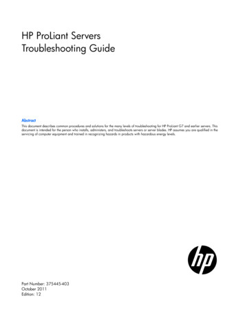
This page will help you navigate our troubleshooting guide. Read the each step carefully and do not skipahead. For additional help, contact technical support by email at support@ecosmartus.com, or call 877474-6473, Monday-Friday, 9:00 am—5:00 pm EST.Existing installations LED display light is not activating with flow rateo Follow Activity B (page 6)LED display light is illuminated on heater, but unit is not heatingo Follow Activity A (page 4)Not receiving power at unito Follow Activity C (page 8)Unit is no longer producing adequate heat, but is activatingo Follow Activity E (page 12), and then Activity F (page 14)New installations (same day install) LED display light is not activating with flow rate, but does when rotating round knobo Follow Activity B (page 6)LED display light is illuminated on heater, but unit is not heatingo Follow Activity C (page 8)Unit is not activating, even when rotating round knobo Follow Activity D (page 10) & E (page 12)Error Codes E 1 - Inlet Thermistor (Page 19)E 2 – Outlet Thermistor (Page 20)E 3 – Both Thermistors (Page 21)E4 – High Temp (Page 22)E 5 – High Flow Rate (Page 23)S 103 – Low Voltage (Page 24)When contacting technical support, please have your model and serial number ready. The serial numberis located on the front cover of the unit. Serial number is printed on a white and black pixelated stickerand begins with the letters S/N followed by numbers (see image below). 2018 All rights reserved. EcoSmart www.ecosmartus.com Page 2
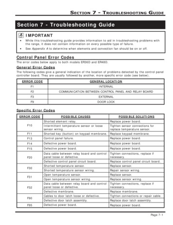
This guide is for use by qualified electrical professional and/or homeowners.This guide takes you through a sequence of steps that MUST be followed.Skipping steps will prevent you from being able to successfully detect andresolve a problem.All electric tankless units are designed to be checked with a multi-clampvolt meter (pictured right) to measure for both voltage and amperage.Below is an inside view of an electric tankless water heater.Always write down any volt meter readings/results before contactingtechnical support.18 2 Heating element (2 chamber heat exchanger)24-27 3 Heating element (3 chamber heat exchanger)36 4 Heating element (4 chamber heat exchanger)For additional help, contact technical support at 877-474-6473, Monday-Friday, 9:00 am—5:00 pm EST,by email support@ecosmartus.com, or on our website ecosmartus.com. 2018 All rights reserved. EcoSmart www.ecosmartus.com Page 3
Activity A Thermistors TroubleshootingEach heater is equipped with two thermistors (see image above). One located on the inlet side (yellow wire)and one located on the outlet side (red wire). The function of the thermistors is to measure the incomingand outgoing water temperature and keep it within 1 to 2 degrees ( or -) of the set temp shown on the LEDdisplay. If the thermistors fail, the heater will still activate, however the control board will not send power tothe elements. Follow these steps to test the thermistors. This activity should take 3 – 7 minutes.Turn off breaker1. Once breaker is off, turn round knob to ensure no power is at unit. Board should not light up ifcorrect breaker is off.2. If board does illuminate the correct breaker was not turned off.Unscrew front cover of unit.3. In order to remove the front cover you will need to unscrew 4 phillip head screws located oneach corner of the cover.4. Two screws located on top of cover facing up and two screws located on the bottom of coverfacing down. .Locate white plastic cover covering control board and remove.5. Cover is located on the upper right had side of unit and secured with 4 Philips head screws. Onein each corner.Locate thermistor on control board (see above image 6 & 12)6. Disconnect inlet and outlet thermistors from control board. (See below image)7. Both wire are quick connect style. To disconnect, lightly pull wires until unplugged.8. Inlet yellow9. Outlet is red 2018 All rights reserved. EcoSmart www.ecosmartus.com Page 4
Turn breaker On10. Leaving thermistors unplugged, turn breaker back to on position.Run water11. Run hot water tap at sink for approximately 2/3 mins. Within this time, the unit should beginto heat water.12. Make sure LED light is illuminated on heater. If not, Make sure the correct breaker was turnedon.Issue resolved.If the heater begins to heat with thermistors disconnected, then these parts need to be replaced. Ifthe heater is still within warranty, part will be covered. If not, parts can be purchased online atAmazon.com or through our support team see links below.a. If the heater begins to heat with thermistors disconnected, then these parts need to bereplaced. If the heater is still within warranty, parts will be covered. If not, parts can bepurchased online at Amazon.com or through our support team.i. istor/dp/B00Z0Z5IP2/ref sr 1 1?s industrial&ie UTF8&qid 1518718177&sr 11&keywords Ecosmart thermistorii. Support info email at support@ecosmartus.com or by phone at 877-474-6473b. Issues not resolvedi. Please go to Activity C Electrical Connection 2018 All rights reserved. EcoSmart www.ecosmartus.com Page 5
Activity B Flow Meter TroubleshootingThe flow meter is located on the inlet side of the water heater and has 4 Phillips head screws and a small black wire(see image above). The flow meter is equipped with a small propeller that must spin freely counter clockwise in orderto activate heater. The flow meter controls the activation of the water heater by sensing water flow. If the flow meteris functioning properly, the LED display will illuminate once water is flowing through the system and will continue tostay illuminated while water is running. If the LED display not illuminated while water is running, follow the stepsbelow.If this is not a new installation (same-day install) skip Step 1.1. The simplest way to clean out flow meter is to run a high volume of water through your system in order toflush out any particles that can be blocking the propeller from spinning freely.a. Turn on at least 5/6 GPM for around 3 minutes. This could be a bath tub, shower, and a sink or 2showers and a sink.b. Once you have a high volume of water flowing through your heater check to make sure your LEDdisplay is illuminated. This can take up to 3 minutes. (If you begin to hear a load humming noisecoming from the heater don't worry this is normal)2. If the LED display is now illuminated with water flow, you can now begin to slow down the GPM's. Close allrunning water taps except for 1 sink to verify your water is been heating and your LED display is staying on.Leave this sink running for approximately 45/60 seconds, within this time the unit should be heating water. (Ifthe LED display is not staying illuminated. Move to Step 3)3.The next exercise is to clean the flow meter, sometimes sediments or debris get caught in the flow meterarea, this will cause the unit not to turn on. Turn breakers to the unit off, shut off water to the unit and open afew faucets of hot water to drain water and relief pressure within the heater.a. Identify flow meter & remove 4 screws and pull cover off, remove impeller and rinse it out. 2018 All rights reserved. EcoSmart www.ecosmartus.com Page 6
4. Place parts back together making sure the impeller is spinning freely and that all the components are in theright order as shown in the pictures below;5. Turn water on and open a few faucets for 3-5 minutes to flush the water lines and make sure there's no airpockets. Skipping this exercise might cause permanent damage to the heating elements.6. Turn on power to the unit and verify if the display remains illuminated with water running. Let water run forapproximately 45/60 seconds, within this time the unit should be heating water. If this does not resolve theissue. This part must be replaced.ii.If this does not resolve the issue. This part must be replaced. If the heater is still within warranty,part will be covered. If not, part can be purchased online at Amazon.com or through our supportteam, see links below.iii. r/dp/B00Z0Z5XXE/ref sr 1 1?ie UTF8&qid 1521129025&sr 81&keywords fsa qc medlrgiv. Support info email at support@ecosmartus.com or by phone at 877-474-6473 Issues not resolvedv. Please go to Activity C Electrical Connection 2018 All rights reserved. EcoSmart www.ecosmartus.com Page 7
Activity C Electrical ConnectionModels 18 - 36 Kilowatts are supplied with a 4 to 6 prong terminal block (depending on model) marked(circuit breaker A - L1 L2) (circuit breaker B - L1 L2) (circuit breaker C - L1 L2) & (circuit breaker D - L1 L2).Each one of the circuit sets must be connected to an in-dependent double pole 40 amp breaker.Circuit A – L1-L1 goes to one 40 amp double pole breaker, Circuit B – L1-L2 goes toanother 40 amp double pole breaker and so on. (See below image.)You must ensure the set of wires from each leg are not crossed at the breakers otherwise the unit willnot function as designed. In order to make sure the wiring is connected correctly perform the followingtest located on the following page. 2018 All rights reserved. EcoSmart www.ecosmartus.com Page 8
Activity C-1 verifying Connection1. Disconnect all breakers at the service panel. Once all breakers have been disconnected measure thevoltage going to each one of the sets (L1 L1) (L2 L2) (L3 L3) & (L4 L4) all should read 0 voltage.2. Now, turn on 1 breaker, it does not matter which one. Once one breaker has been turned on,using your voltmeter place one probe on L1 and the other probe on the other L1, measure across (L1L1) you should get a reading of 208-240v. Do the same for (L2-L2), (L3-L3) and (L4L4) (see aboveimages for example.)a. If you measure voltage across one of the legs in a set and voltage in another leg of another set, then your wires at the breakers are crossed and must be corrected. Example–L1-L1 reads no voltage, but L1-L2 gives you voltage reading,then your wires at the breakers are crossed and must be fixed.Perform this voltage reading on all legs of terminal block both at the bottom and top of terminal blockturning on 1 breaker at a time. If power going to the unit is not correct, the unit will not operate correctly,so it is important to perform this test first, before proceeding. The problem might not be at the unit,but at your electrical panel, or breakers. 2018 All rights reserved. EcoSmart www.ecosmartus.com Page 9
Activity D Checking FuseEach heater is equipped with one inline fuse. This fuse is designed to protect the control boardagainst power surges. Depending on your model, your heater will have one of two fuses. Followbelow steps to locate and test the fuse.Fuse A /250 Volt 3 AMP1. Locate plastic housing covering the LED control board. See below images for help.a. Make sure breaks are turned off.b. Remover round knobc. Locate 4 philips head screws, 1 in each corner of housing and remove.d. Locate round black fuse holder on top of housing and open.e. Insert new fuse (250V 3 Amp)and put holder back togetherf. Turn on breakers and verify if unit is turning on. 2018 All rights reserved. EcoSmart www.ecosmartus.com Page 10
Fuse B/250 volte 500 milliamps Fast Acting1. Locate plastic housing covering the LED control board. See below images for help.a. Make sure breaks are turned off.b. Remover round knobc. Locate 4 philips head screws, 1 in each corner of housing and remove.d. Locate fuse on upper right hand corner of board.e. Insert new fuse (250V-200-400 mA)f. Turn on breakers and verify if unit is turning on. 2018 All rights reserved. EcoSmart www.ecosmartus.com Page 11
Activity E Checking ElementsThe following steps verify the heating elements are working correctly. The heating elements willonly draw voltage when hot water is being called for and uses only the voltage needed based onthe temperature setting. This feature is called self-modulation. When hot water is ‘demanded’the elements instantly draw power. The heating elements then work in series, which means thatthe element #1 (located on the inlet side of the unit) will be the first to draw power. In order forthe second element to draw power, the first element must be drawing at 100% capacity.1. Locate elementsa. There are two red wires connected to the top of the element. In order to check if theelement is working you must turn on a hot water tap. We suggest that you run theshower or sink. This way both elements will draw voltage and can be checked. Once youhave water running through the unit, the LED display will light up and display thetemperature setting on the unit. Using your volt meter-place one probe on one screwand the other probe on the other screw located on the top of the element. (See aboveimage) check what voltage you are drawing.b. When measuring voltage across the top of the elements you will get a voltage readingbetween 220v – 240v. Remember– you must have water running in order for theelements to activate and draw power.c. If your LED display is illuminated and you have water running through the unit and havea 0 voltage reading when measuring with probes on each screw – perform conductivitytest ( turn breaker off , set your meter for ohms and place one probe on one screw andthe other probe on the other screw located on the top of the element. (See aboveimage) take reading.i. If the reading is in the range of 6- 10 omhs, the element is good and it will benecessary to contact our support team for further troubleshooting. 2018 All rights reserved. EcoSmart www.ecosmartus.com Page 12
ii. If the ohm reading is lower than 5 or higher than 10, the element will need to bereplaced. Common element failures are due to air pockets, scale/sediment buildupand or freeze damage. . Please Note: It is the responsibility of the user to be aware oftheir respective water quality and its effect on the heater. Failure to maintenance yourproduct may result in damage to the heating elements or heat exchangers caused bysediment/mineral and or lime build up. This is not covered by the warranty.d. If you notice your element has failed do to scale/sediment buildup. Please follow theRequired Maintenance page.If the heater is still within warranty, part will be covered. If not, part can be purchased online atAmazon.com or through our support team. Follow links below.i. ement/dp/B00Z0Z5J4M/ref pd sim 60 1? encoding UTF8&pd rd i B00Z0Z5J4M&pd rd r 7XV5X49JRPG6XGFVWCPQ&pd rd w 9PcS8&pd rd wg toK58&psc 1&refRID 7XV5X49JRPG6XGFVWCPQii. Support info: 877-474-6473 or Support@ecosmartus.com 2018 All rights reserved. EcoSmart www.ecosmartus.com Page 13
Activity F Required MaintenanceWhen scale forms on elements, it is due to minerals such as calcium and magnesium found inwater. There are three ways to deal with this this issue. Manual Maintenance, RecirculatingMaintenance, and Filtration Maintenance.Please Note: It is the responsibility of the unit owner to be aware of your water quality and its effecton the heater. Failure to properly maintain your unit may result in damage to the heating elementsor heat exchangers if sediment/mineral and/or lime build up. This damage is not covered by thewarranty. See below recommend water quality levels.Manual MaintenanceDepending on how hard the incoming water is, maintenance may need to be performed every 6to 12 months. What is needed: 1 five gallon bucket and 3 to 4 gallons of undiluted white vinegar(food grade)1. Turn OFF breakera. Once breaker is off, turn round knob to ensure no power is at the unit.LED display will not light up if the correct breaker is off.b. If LED display does light up, correct breaker was not turned off.2. Turn off water going into unita. Per national plumbing codes, there must be a shut-off valve within 5 to 10 feet fromthe water heater. If there is not a dedicated shutoff valve, shut off the main waterline to home.b. Once water is off, verify this by turning a tap ON at a sink. Turn tap on to hot sideand let run until water is dripping lightly and leave open to relief pressure.3. Remove front cover of unita. In order to remove the front cover you will need to unscrew 4 phillip head screwslocated on each corner of the cover.b. Two screws located on top of cover facing up and two screws located on the bottomof cover facing down. 2018 All rights reserved. EcoSmart www.ecosmartus.com Page 14
4. Locate heating elementsa. Depending on model, the unit may have either 1 or 2 heating elements.b. Locate heating elements and remove both Philips head screws on top of elementand fold red wires back (see images below).5. Remove elementa. The element has a brass hexagon manifold located on top. Grip hexagon brass top ofheating element and rotate counter clockwise to unscrew from the copper tank, seepicture below;Cleaning Processa. Place elements in a small bucket and add white vinegar. Cover element to just underhexagon brass top. Do not submerge whole element. Vinegar can also be poured intoheating chamber if needed. We recommend letting elements soak for at least 3 hours.Replacing Elementsa. Insert and rotate heating element clockwise until tightb. Reset red wires and tighten screwsc. Turn water ON to unit. Inspect for leaks. (If an element is not fully tightened down, itmay leak.)d. Open a few hot water faucets for 2 to 3 minutes to remove air pockets in the linesFiltration MaintenanceFor filtration maintenance we recommend consulting your local water company or a water filterspecialist. You can find these filter systems at most hardware and plumbing supply stores, oronline. It is important to regulate calcium, lime and sediment levels in your water before itenters your tankless water heater 2018 All rights reserved. EcoSmart www.ecosmartus.com Page 15
Recirculating MaintenanceWhat is needed: 1 five gallon bucket, 1 four gallon-per-minute recirculating pump, two ¾ inch femalehoses, and 3 to 4 gallons of undiluted white vinegar (food grade). Depending on the hardness of thewater in your area, you may need to perform this maintenance once to twice a year.See diagram on page 17.Flushing the Heat Exchanger1.2.3.4.5.6.7.8.9.10.11.Disconnect electrical power to the water heaterClose shut off valves for both hot and cold water linesPlace bucket under service valve of hot water lineUnscrew cap from service valve on hot water lineLet water from heater drain completely into bucketUnscrew cap from service valve on cold water lineConnect pump outlet hose to service valveConnect drain hose to service valve on hot water linePour 4 gallons of white vinegar into bucketPlace drain hose and pump inlet hose into the vinegarOperate the pump and allow vinegar to circulate through the water heater for at least 3 hours ata rate of 4 gallons per minute.Rinse Vinegar from Water Heater1. Remove free end of drain hose from bucket and put in a sink or outside to drain2. Allow vinegar to completely drain from drain hose3. Disconnect pump outlet hose from service valve on the cold water line. Use bucket to captureany excess water that may be in the line.4. Screw cap tightly back onto service valve of cold water line*5. Open shut-off valve on cold water line6. Allow water to flow through water heater for 5 minutes as it continues to drain7. Close shut-off valve on cold water line and allow heater to drain completely8. Remove drain hose from service valve on hot water line9. Screw cap tightly back onto service valve*10. Open both cold and hot water line shut off valves11. Open a few faucets of hot water for 2-3 minutes to remove any air pockets in the lines12. Restore electrical power to the water heater 2018 All rights reserved. EcoSmart www.ecosmartus.com Page 16
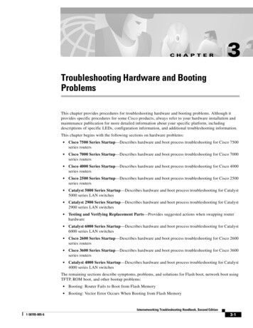
Activity G SizingMeeting temperature rise (ability to heat water to set/desired output temperature) for anelectric tankless water heater is dependent on the climate/region where a heater is installed.Colder incoming water requires a larger kilowatt model. The same applies for flow rate. To meetthe demand for higher flow rates, a higher kilowatt model is needed. There are 3 pieces ofinformation needed to determine what size electric tankless water heater is right for you.Note: The voltage you are receiving at the terminal will depend how many kilowatts (kW) your unit canpull. If you are receiving power lower than 220v, your unit decreases in kW by 25% giving you a lowertemperature rise. For example: an 11 kW model receiving power lower than 220 volts will become an8.25 kW model. Watts: Amount of energy needed to heat water to meet set/desired temperatureTemperature Rise: Difference between inlet water temperature and set/desired outlettemperatureFlow Rate: Measured in gallons per minute (GPM)The chart below will assist in selecting the correct model based on your location.Certified through the ETL Nationally Recognized Testing Laboratory to UL 499 and CSA. 2018 All rights reserved. EcoSmart www.ecosmartus.com Page 17
E-1 Error code Inlet ThermistorIf you unit is displaying an E1 error code. Your unit is notifying you the inlet thermistor is notreading correct Temperature and may need to be replaced. In order to temporary resolve thisissue please follow the below steps. Keep in mind, this is only a short term fix. You will still beresponsible for replacing you inlet thermistor.Bypassing E1 Error Code1.2.3.4.Turn on water so LED display is on and reading E1 errorHold down round knob for 3/5 seconds and release.At this point your LED display should be reading CE1Keep water running for 2/3 mins and check for hot water.This work around will allow you to receive hot water while waiting for the replacement part.While your unit is running in the CE1 mode, the heat will default to 125 degrees as a normal tankheater would. In this mode you will not be able to control your outlet temperature. Keep in mindyou may need to mix some cold water in order to reach the desired Temperature. If the heater is still within warranty, part will be covered. If not, parts can be purchasedonline at Amazon.com or through our support team see links below.o ement/dp/B00Z0Z5J4M/ref pd sim 60 1? encoding UTF8&pd rd i B00Z0Z5J4M&pd rd r 7XV5X49JRPG6XGFVWCPQ&pd rd w 9PcS8&pd rd wg toK58&psc 1&refRID 7XV5X49JRPG6XGFVWCPQo Support info: 877-474-6473 or Support@ecosmartus.com 2018 All rights reserved. EcoSmart www.ecosmartus.com Page 18
E 2 Error Code Outlet ThermistorIf you unit is displaying an E2 error code. Your unit is notifying you the outlet thermistor is notreading correct Temperature and may need to be replaced. In order to temporary resolve thisissue please follow the below steps. Keep in mind, this is only a short term fix. You will still beresponsible for replacing you inlet thermistor.Bypassing E1 Error Code1.2.3.4.Turn on water so LED display is on and reading E2 errorHold down round knob for 3/5 seconds and release.At this point your LED display should be reading CE2Keep water running for 2/3 mins and check for hot water.This work around will allow you to receive hot water while waiting for the replacement part.While your unit is running in the CE2 mode, the heat will default to 125 degrees as a normal tankheater would. In this mode you will not be able to control your outlet temperature. Keep in mindyou may need to mix some cold water in order to reach the desired Temperature. If the heater is still within warranty, part will be covered. If not, parts can be purchasedonline at Amazon.com or through our support team see links below.o ement/dp/B00Z0Z5J4M/ref pd sim 60 1? encoding UTF8&pd rd i B00Z0Z5J4M&pd rd r 7XV5X49JRPG6XGFVWCPQ&pd rd w 9PcS8&pd rd wg toK58&psc 1&refRID 7XV5X49JRPG6XGFVWCPQo Support info: 877-474-6473 or Support@ecosmartus.com 2018 All rights reserved. EcoSmart www.ecosmartus.com Page 19
E 3 Error Code Outlet & Inlet ThermistorsIf you unit is displaying an E3 error code. Your unit is notifying you the outlet & inletthermistor is not reading correct Temperature and may need to be replaced. In orderto temporary resolve this issue please follow the below steps. Keep in mind, this isonly a short term fix. You will still be responsible for replacing you inlet thermistor.Bypassing E1 Error Code1.2.3.4.Turn on water so LED display is on and reading E3 errorHold down round knob for 3/5 seconds and release.At this point your LED display should be reading CE3Keep water running for 2/3 mins and check for hot water.This work around will allow you to receive hot water while waiting for thereplacement part. While your unit is running in the CE3 mode, the heat will default to125 degrees as a normal tank heater would. In this mode you will not be able tocontrol your outlet temperature. Keep in mind you may need to mix some cold waterin order to reach the desired Temperature. If the heater is still within warranty, part will be covered. If not, parts can bepurchased online at Amazon.com or through our support team see linksbelow.o ement/dp/B00Z0Z5J4M/ref pd sim 60 1? encoding UTF8&pd rd i B00Z0Z5J4M&pd rd r 7XV5X49JRPG6XGFVWCPQ&pd rd w 9PcS8&pd rd wg toK58&psc 1&refRID 7XV5X49JRPG6XGFVWCPQo Support info: 877-474-6473 or Support@ecosmartus.com 2018 All rights reserved. EcoSmart www.ecosmartus.com Page 20
E 4 Error Code High TemperatureIf the LED control board is displaying an E4 error code. The unit is reading an incoming watertemperature of 150 degrees or higher. This heater is equipped with 2 - 4 thermostats(depending on you model) all rated a 140 F. This unit is not rated to heat past 140 degrees. Ifyour control board is displaying this error code, you will need to lower the incoming watertemperature under 140F. Once the unit is receiving water under 150 degrees the LED display willilluminate with desired set temperature.For further assistants please contact our support team via phone @ (877) 474-4673 or via emailat support@ecosmartus.com 2018 All rights reserved. EcoSmart www.ecosmartus.com Page 21
E 5 Error code High Flow RateIf the LED control board is displaying an E5 error code the desired volume of water is too highand you will need to slow down the Flow rate. Each sink, shower or tub is equipped with anaerator to control the volume of water. Sinks 1 – 2.5 GPM (gallons per min) Showers 1.5 – 3 GPM Bathtubs 3.5 – 8 GPM Washing machines 1.5 – 2.5 GPMIn order to see what flow rate is currently running through the system follow the steps below From the temperature display screen (ON) - Press and hold the button for 10 secs to getto the diagnostics screenIn the diagnostics menu you can navigate through 3 screens by rotating the round knobcounter clockwise.o First Display inlet water temp (see below for example) l088 88 F l105 105FFirst turn Outlet water temp (see below for example)o O088 88 Fo O105 105FSecond turn Current flow rate. In this screen there is a hidden decimal point. See belowfor exampleo F 005 00.5 GPMo F 049 04.9 GPMo F101 10.1 GPMIf the LED control board is displaying an E5 error, you will need to slow down the volume ofwater passing through the system until the LED display begins to read the selected degrees. Inorder to do this, we recommend installing a flow restrictor or slightly close the incoming oroutgoing water valve. Flow restrictors can be purchased at most hardware stores, onlineretailers or directly from our company. 2018 All rights reserved. EcoSmart www.ecosmartus.com Page 22
S103 Error Code Low VoltageIf the LED control board is displaying an S103 error code, your unit may not be receiving the correctpower to the system. These heater requires at least 208 volts in order to function correctly. Pleasefollow Activity C (page 8) to test the incoming power to the system. One the heater has the correctincoming power, the system the LED display the selected temp and water will begin to heat.For further assistants please contact our support team via phone @ (877) 474-4673 or via emailat support@ecosmartus.com 2018 All rights reserved. EcoSmart www.ecosmartus.com Page 23
EcoSmart Troubleshooting Guide Models ECO 18 – 36 kW This guide is designed for installers or homeowners to help troubleshoot any issues experienced during the lifetime of the tankle