Transcription
SERVICE MANUAL12VDC WALL THERMOSTATAIR CONDITIONINGSYSTEMSROOFTOP UNITS ONLY! WARNING - SHOCK HAZARD!TO PREVENT THE POSSIBILITY OF SEVERE PERSONAL INJURY, DEATH, OREQUIPMENT DAMAGE DUE TO ELECTRICAL SHOCK, ALWAYS BE SURE THEPOWER SUPPLY TO THE APPLIANCE IS DISCONNECTED BEFORE DOING ANYWORK ON THE APPLIANCE. THIS CAN NORMALLY BE ACCOMPLISHED BYSWITCHING THE BREAKER FOR THE AIR CONDITIONER TO OFF,DISCONNECTING ALL EXTERNAL ELECTRICAL CONNECTIONS AND CORDS,SWITCHING ON BOARD ELECTRICAL GENERATORS AND INVERTERS TO OFF,AND REMOVING THE CABLE FROM EACH POSITIVE TERMINAL ON ALLSTORAGE AND STARTING BATTERIES.DANGERSOME DIAGNOSTIC TESTING MAY BE DONE ON ENERGIZED CIRCUITS.ELECTRICAL SHOCK CAN OCCUR IF NOT TESTED PROPERLY. TESTING TO BEDONE BY QUALIFIED TECHNICIANS ONLYThe steps outlined in this manual are intended to guide the service technician through theprocess of correctly diagnosing a Coleman Mach series rooftop air conditionerwith a remote wall thermostat control system.Page -1-
TABLE OF CONTENTSPAGEI.INTRODUCTION TO WALL THERMOSTATS .3IIINTRODUCTION TO RELAYS . 5HOW DO RELAYS FUNCTION . 5IIICHECKING CEILING PLENUMS WITH INDIVIDUALRELAYS . 6IVCHECKING CEILING PLENUMS WITH PRINTEDCIRCUIT BOARDS . 8CHECKING THE THERMOSTAT OPERATION . 9CHECKING THE PRINTED CIRCUIT BOARDOPERATION . 10VDIAGNOSTIC FLOW CHARTS .VIWIRING DIAGRAMS . 1611Page -2-
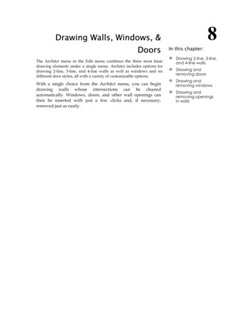
I.INTRODUCTION TO WALL THERMOSTATSAll of the air conditioning functions are controlled by the wall mounted thermostat . Thesethermostats utilize a 12 VDC electrical circuit which is supplied by the vehicle manufacture or theinstaller of the A/C unit. Most of the thermostats provided by Recreation Vehicle Productsare combination (Heat / Cool) thermostats. These thermostats are capable of operating both theroof top air conditioner and any furnace with a 12 VDC control circuit.The Figures below list three of the most commonly found Coleman/RV Products Wall MountedThermostats for rooftop air conditioners (heat pumps excluded). These thermostats are listed inchronological order from the oldest to the newest.1. Mechanical / By-Metal Thermostats2.Electronic ThermostatsHeating Anticipator3.Electronic Digital Display ThermostatsNOTE:ALL THREE OF THESE THERMOSTATS ARE COMPLETELY INTERCHANGEABLE.Thermostats are really nothing more than temperature controlled switches. When the need forCooling or Heating exists the thermostat sends a 12VDC( ) signal to the control relays or a P.C.board which in turn energizes the air conditioner components or the furnace. (Note: Relays andP.C. boards will be further discussed later in lesson II).Page -3-
The following chart shows the different electrical connections made by the thermostat duringoperation. The chart below assumes12VDC( ) is supplied to thermostat Red wire “R” and that12VDC(-) or ground is supplied to the Blue wire “B” at all times.Thermostat OperationsInternal 12VDC( ) Connections MadeCool Mode Selected On Low FanRed “R” to Yellow “Y” and Gray “GL”Cool Mode Selected On High FanRed “R” to Yellow “Y” and Green “GH”Heat Mode Selected On Any Fan Speed(Note: Furnace blower operates independentlyfrom sequencer or time delay in furnace)Red “R” to White “W”Fan Only Selected (Hi-Fan Only)Red “R” to Green “GH”Note: When the auto cool mode is selected on the thermostat the fan cycles “on” and “off” with thecompressor as needed. When the on cool mode has been selected the fan runs continuously and thecompressor cycles “on” and “off” as needed.The following chart depicts thermostat wiring and the wiring destinations for air conditioners withcontrol boxes containing Printed Circuit Boards.THERMOSTATTERMINAL /WIRECONTROL AND SUPPLYWIRING (OEM / VENDOR)CEILING ASSEMBLYTERMINALDESIGNATIONR or REDONE RED, ( ) 12VDC SUPPLYWIRE TO THE THERMOSTATN /AB or BLUETWO BLUE, ONE (-) 12VDC SUPPLY WIRETO THE THERMOSTAT AND ONE BLUEWIRE TO CEILING ASSEMBLY / PLENUMBY or YELLOWONE YELLOW, COMPRESSOR CONTROLWIRE TO CEILING ASSEMBLY / PLENUMYGH or GREENONE GREEN, HIGH FAN CONTROL WIRETO CEILING ASSEMBLY / PLENUMGHGL or GRAYONE GRAY, LOW FAN CONTROL WIRETO CEILING ASSEMBLY / PLENUMGLW or WHITEONE WHITE, 12VDC ( ) FURNACECONTROL WIRE FROM THETHERMOSTATNOTE: The (W) White wire is not available on COOL ONLY thermostats.FURNACENOTE: THE CONNECTING WIRES TO THE THERMOSTAT ARE PROVIDED BY THEVEHICLE MANUFACTURER OR INSTALLER. THESE O.E.M. OR VENDOR SUPPLIEDWIRES MAY NOT BE COLOR CODED AS NOTED IN THE CHART ABOVE.THE GROUND WIRE MUST BE A ZERO “0" RESISTANCE GROUND.Page -4-
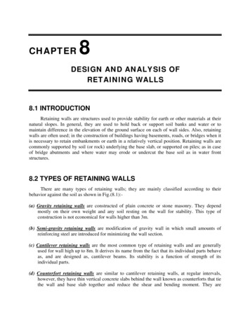
THERMOSTAT LOCATIONThermostats are very sensitive instruments. For accurate temperature control and comfort thefollowing considerations for thermostat locations should be taken into account:1.Locate the thermostat on an inside wall about five foot above the floor. Pick a dry area whereair circulation is good. The thermostat should be mounted within a reasonable distance fromthe appliance the thermostat will control. This will assure a more accurate temperaturerelationship between the thermostat and the appliance the thermostat will control.2.Do not install the thermostat where there are unusual heating conditions; such as directsunlight, heat producing appliances (television, radio, wall lamp, etc.); or a furnace or airconditioner supply register.3.Note: When installing or servicing these thermostats the technician should take all necessaryprecautions not to short any positive wire to ground. Permanent damage to the thermostatmay occur. Make sure all connections are good and tight. Loose connections may causerelay chattering which leads to welded relay contacts on air conditioner printed circuitboards.II.INTRODUCTION TO RELAYSIn the previous chapter on thermostats we learned the wall thermostat makes necessary connectionsthat provide low voltage power to initiate all of the air conditioning or heating functions. There is onequestion left unanswered. How do we use this 12VDC power to operate a 115VAC appliance?THE ANSWER IS: We use relays or printed circuit boards with relays located on them.HOW DO RELAYS FUNCTIONSo what is a relay? A relay is defined as an electromagnetic mechanism moved by a small electricalcurrent in a control circuit (12VDC in this case). How does this relay work? As this mechanismmoves back and forth in the relay it will open or close a set of contacts capable of carrying highvoltage and (115VAC in this case). All of our control circuit relays are normally open and thecontacts close as power from the thermostat is applied.As shown in Figure 1. on the next page, the 115VAC power to the compressor is interrupted by a setof normally open contacts on the relay. In order for these contacts to close 12VDC must be appliedby the wall thermostat to the relay coil. When the thermostat switch is placed in the cool position12VDC( ) travels from the thermostat red wire to the thermostat yellow (Y) wire and then to therelay coil. When the coil is activated an electromagnet inside the relay will pull the contacts closed.The 115VAC will now operate the compressor until the thermostat opens or the system switch isturned to the off position.Figure 1. shows a very simplified control circuit for compressor operation only. The entire controlcircuit for the A/C / Heating system would include the rest of the thermostat functions and possibly 2or 3 more relays. In addition to the compressor relay you would need a separate relay for Low Fan,one for High Fan, and possibly one for Heat, if a heat pump or electric heating element is used.Please refer to the previous lesson or use the chart below for proper wiring from the wall thermostatto each individual relay.Page -5-
Figure 1III.CEILING PLENUMS WITH INDIVIDUAL RELAYSRecreational Vehicle Products built 2 types of ceiling assembly packages which incorporateindividual relays for the air conditioner system functions. Line drawing examples of these two ceilingassembly types are shown in figures 2 and 3.Figure 2.Page -6-
Figure 3The following charts depict the thermostat control wiring, ceiling assembly wiring destinations, andrelay functions for air conditioners with control boxes containing individual relays6799-720 & -726 SERIES, 7330-720 & 726 SERIES CEILING PLENUMSTHERMOSTATYellow (Y)Green (GH)Gray (GL)Blue (B) (12VDC-)White (W)CEILING PLENUM WIRE*YellowGreenGrayBlueWhiteUNIT OPERATIONCompressor relayHigh Fan relayLow Fan relayN/AFurnace or Heat Element relay6799-730 SERIES CEILING PLENUMTHERMOSTATCEILING PLENUM WIRE*UNIT OPERATIONYellow (Y)BlackCompressorGreen (GH)GreenHigh FanGray (GL)GrayLow FanBlue (B) (12VDC-)BlueN/AWhite (W)WhiteFurnace or Heat Element relay.* The low voltage wiring connections for the these control systems are hard wired by themanufacturer or installer of the unit and they may not all use color coded wire as noted above.Note: If the heating system includes a gas fired furnace the thermostat white wire will energize thePage -7-
furnace control circuit, (Usually a time delay relay located at the furnace).IV.CEILING PLENUMS WITH PRINTED CIRCUIT BOARDSMost of the 7000 and 8000 series ceiling plenums built since 1992 have had Printed Circuit Boardsinstead of individual relays. Printed circuit boards are less costly and require less wiring. The PrintedCircuit Boards all have relays mounted permanently on them. Even though the boards may look muchmore complicated they are very easy to troubleshoot. On the following pages you will find somevisual aids that will help you trouble shoot these units without removing the thermostat or the airconditioner control box lid.Recreational Vehicle Products has and is building many ceiling assembly packages which use PrintedCircuit Boards to control air conditioner system functions. Just like the individual relays, the PrintedCircuit Board must receive a signal from the wall thermostat to operate.A common ducted ceiling assembly application is shown here in Figure 4.Figure 4Page -8-
Note: In ducted applications similar to the one found in Figure 4, the Printed Circuit Board /Control Box Assembly is found mounted in the return air opening of the Air Conditioner. Insome older applications the Printed Circuit Board / Control Box Assembly will be located inthe center of the roof opening just above the return air grille.Figure 5 shows an exploded view of the Control Box AssemblyFigure 5CHECKING THE THERMOSTAT OPERATIONThe 12 Volt DC signal from the wall thermostat may be checked at the Low Voltage Terminal Strip(Figure 6) located externally on the ceiling plenum wiring boxFigure 6. Low Voltage Terminal StripAnytime the thermostat is placed in the FAN ONLY position you should be able to read12VDC between terminals GH and B at the Low Voltage Terminal Strip (see figure 6) .Anytime the thermostat is placed in the LOW COOL position you should be able to read12VDC between terminals GL and B for the Low Fan, and between terminals Y and B forcompressor operation.Page -9-
Anytime the thermostat is placed in the HIGH COOL position you should be able to read12VDC between terminals GH and B for the High Fan, and between terminals Y and B forCompressor operation.Note: Thermostat operation in the Heating Mode cannot be tested at the Ceiling Assembly LowVoltage Terminal Strip if the thermostat is operating a gas fired furnace.Note: The wall thermostat will be equipped with an optional Electric Heat / Gas Heat switch if theRecreational Vehicle is equipped with a Heat Pump or with an Electric Heating Element. Inthis case the Electric Heat Mode may be checked the Low Voltage Terminal Strip. In eithercase the Low Voltage Terminal Strip will have an additional terminal labeled “W” for electricheating operation. When Electric Heat is chosen at the thermostat you should be able to read12VDC between terminals W and B. Please note, the “W” terminal is not shown on the LowVoltage Terminal Strip (Figure 6) or in the chart below because it is not tremendouslycommon.THERMOSTATCEILING ASSEMBLY TERMINALUNIT OPERATIONYellow (Y)(Y)CompressorGreen (GH)(GH)High FanGray (GL)(GL)Low FanBlue (B) (12VDC-)(B)N/AIf you do not find voltage at the Ceiling Assembly Low Voltage Terminal Strip as described abovethe problem needs to be traced back to the thermostat or the vehicles low voltage wiring.CHECKING THE PRINTED CIRCUIT BOARD OPERATIONLow voltage MUST be verified at the Low Voltage Terminal Strip as described earlier in this text oras noted in the chart below before preceding to the next step, or checking the Printed Circuit Board.In order to continue you must first verify the 115VAC power source to the Air Conditioner ControlBox Assembly. If the 115VAC power source is NOT present, all of the Air Conditioner functions willbe dead and power must be restored to continue. 115VAC power must be present to the CircuitBoard if any one of the Air Conditioner functions are working.The operation of the printed circuit board may be checked at the High Voltage 9-Pin Connector(Figure 7) without removing the electric box lid. The chart below shows the 115VAC connectionsmade by the Circuit Board to the High Voltage 9-Pin ConnectorTHERMOSTAT CONNECTIONSAT THE LOW VOLTAGETERMINAL STRIP12VDC at Y and B12VDC at GH and B12VDC at GL and B115VAC CONNECTIONSMADE BETWEEN TERMINALSAT THE 9 PIN CONNECTORTerminals # 1 and # 3Terminals # 5 and # 9Terminals # 6 and # 9Page -10-
Figure 7. High Voltage 9-Pin ConnectorNote: To check voltage at the 9 pin connector plug it may be necessary to unplug the upper unit fromthe control boxIf the Air Conditioner is still not functioning and both 12VDC and 115VAC are present andaccountable at their proper locations the problem is located in the upper unit.If the correct 115VAC connections are NOT made at the 9 pin connector plug after12VDC poweris applied to the Low Voltage Terminal Strip; the problem is in the Printed Circuit Board withone exception as described below.The low temperature freeze thermistor could open the compressor relay on the Circuit Board if the AirConditioner Evaporator Coil starts to freeze. If this switch is opens you would still have 12VDC atterminals Y and B, but no voltage would be present at terminals 1 and 3 in the High Voltage 9-PinConnector. The Freeze Thermister opens if the evaporator coil temperature drops below 32 degrees andcloses at 55 degrees. The probe end of this switch should be found pushed into the fins of the evaporatorcoil and the wires are hooked to the Printed Circuit Board. It is OK to remove the thermister wire fromthe Board and jump around these terminals fore diagnostic purposes.If the Air Conditioner compressor is running and NO VOLTAGE is found between terminals Yand B on the Low Voltage Terminal Strip the Printed Circuit Board must be replaced. Thecompressor relay has evidently welded shut.In conclusion, you can save a lot of time if you get in the habit of going immediately to the ducted controlbox assembly for trouble shooting purposes. There in a matter of minutes you can tell if the problem isin the Thermostat, the Printed Circuit Board, or the Upper Unit.V.DIAGNOSTIC FLOW CHARTSNote: When working with the following diagnostic flow charts, start at the top left corner and worktowards the right or down the page as applicable. Do not skip around or start in middle withoutperforming all prior steps.DANGERTHE FOLLOWING DIAGNOSTIC TESTING WILL BE DONE ON ENERGIZEDCIRCUITS. ELECTRICAL SHOCK CAN OCCUR IF NOT TESTED PROPERLY.TESTING TO BE DONE BY QUALIFIED TECHNICIANS ONLYPage -11-
Page -12-
Page -13-
Page -14-
Page -15-
VI.WIRING DIAGRAMS7330-730 & 8330-733 Series Cool Only Ducted Ceiling Plenums7330-735, 7330-736 & 8330-735 Series Heat/ Cool Ducted Ceiling PlenumsPage -16-
7330-720 & 8330-723 Series Cool Only Remote Free Delivery Ceiling Plenums7330-725, 7330-726 & 8330-725 Series Heat/Cool Remote Free Delivery Ceiling PlenumsPage -17-
RV ProductsA Division of Airxcel, Inc.P.O. Box 4020Wichita, KS 672041976-376 (4-02)Page -18-
Page -3-I. INTRODUCTION TO WALL THERMOSTATS All of the air conditioning functions are controlled by the wall mounted thermostat . These thermostats utilize a 12 VDC electrical circuit which is supplied by the vehicle manufacture or the installer of the A/C unit.