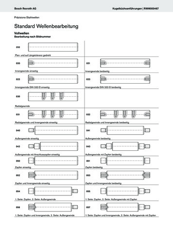
Transcription
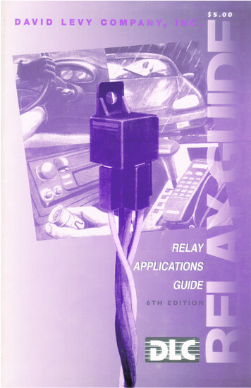
th6thEDITIONEDITIONDear Installer,We are excited about our 6th Edition Relay ApplicationGuide! This book is offered FREE any time you place anorder with us.The Guide has been revised and expanded to 44 pages ofvaluable tech tips featuring circuits designed by leadinginstallers and installation support teams from around thecountry.With more than 40,000 copies in print, DLC's RelayApplication Guide has become an important reference toolfor installers everywhere. Many positive changes in our latest book include a reorganized layout by subject and additional applications for specific vehicles.With a greater variety of circuits to choose from and an easier format to use,we know you'll find time-saving tips and solutions to thoselittle challenges that pop up from time to time.Whetheryou're starting to get your feet wet or are a seasoned veteran, the DLC Relay Application Guide will prove to be ahandy tool to have around the shop.So, to all of those who have contributed to the 6th Editionwith some ingenious applications or technical assistance,our thanks and recognition.Enjoy,David LevyP.S. By the way, if you have a relay application for our nextedition, send it to us, we’d like to here from you.DAVID LEVYCOMPANY, INC.
TA B L E O F C O N T E N T SSECURITYDoor LocksAdding Door LocksNegative Alarm Trigger. . . . . . . . . . . . . . . . . . . . . 4Adding Door Locks- Positive Alarm Trigger . . . . . 4Negative Pulse Door Locks/Negative Alarm Output . 5Positive Pulse Door Locks/Negative Alarm Output . . 5Reverse Polarity Door Locks/Rest at Ground . . . 6Reverse Polarity Door Locks/RestOpen Circuit (A) . . . . . . . . . . . . . . . . . . . . . . . . . 6Reverse Polarity Door Locks/RestOpen Circuit (B) . . . . . . . . . . . . . . . . . . . . . . . . . 7Interface W/Dual Voltage Systems- 1994 Probe . . 7Door Lock Systems using Vacuum Pump . . . . . . . 8Passenger Door Unlock Bypass Circuit/Universal . . . 8Selective Door Unlock/Negative Pulse System. . . 9Selective Door Unlock/Positive Pulse System . . . 9Selective Door Unlock/Reverse Polarity System . . 10Specialty Door Locks/93 Chrysler LeBaron/Dodge Daytona . . . . . . . . . . . . . . . . . . . . . . . . . 10Specialty Door Locks/(-) Pulse/InterruptDoor Locks- Nissan. . . . . . . . . . . . . . . . . . . . . . 11Specialty Door Locks/1994 Range Rover . . . . . . 11Specialty Door Locks/85-86 Toyota Van . . . . . . . 12Specialty Door Locks/Door Locks- Volvo. . . . . . 12Separate Left/Right Parking Light Circuits (A)Separate Left/Right Parking Light Circuits (A)Left to Right Flashing High Beams . . . . . . . . .Left to Right Flashing Lights . . . . . . . . . . . . . .Horn Honk/Light Flash Circuit. . . . . . . . . . . .Flasher/Honker Circuit . . . . . . . . . . . . . . . . .Alternately Flashing Park Light/Horn . . . . . . .Parking Light Safety Flasher . . . . . . . . . . . . . .Wiper Turn-On Parking Lights & Headlights .Wipers/Lights Turn-On Together . . . . . . . . . .Courtesy/Car Identifier Lights . . . . . . . . . . . .Audible “Chirp” to Visual “Blink” ConversionFlasher LED to Light Converter. . . . . . . . . . .Basic Fog Light Systems . . . . . . . . . . . . . . . . .Auxiliary Fog Light Control . . . . . . . . . . . . . .232324242525262627272828292930AUTOSOUND & CELLULARIgnition Bypass to Eliminate Noise . . .Amp System Remote Power Switch. .Switching Module. . . . . . . . . . . . . . . .Accessory Power Back-up Circuit . . .Automatic Antenna Switching Relay . .Auto Antenna Protector . . . . . . . . . .Stereo Disable with Cigarette LighterHorn Alert for Cellular Phones . . . . .Horn Alert with Buzzer . . . . . . . . . . .303131323233333434Starter DisableStarter Kill via Hidden Toggle Switch . . . . . . . . . 13Hidden Toggle Starter Disable/Extra Security. . . 13Ignition Kill Circuit. . . . . . . . . . . . . . . . . . . . . . . 14Safety Starter Cut-off. . . . . . . . . . . . . . . . . . . . . 14Stealth Starter Interrupt . . . . . . . . . . . . . . . . . . 15Starter Disable/Cigarette Lighter Inoperative. . . 15Starter Disable/Cigarette Lighter Operative . . . 16Keyless Entry w/Cigarette Lighter/Extra Security. . 16LATCHING TYPESSimple Latch(-) Turn-On, ( ) Turn-Off/(-) Output .Simple Latch(-) Turn-On, (-) Turn-Off/( ) Output .Simple Latch( ) Turn-On, Remove (-) Turn-Off,( ) Output. . . . . . . . . . . . . . . . . . . . . . . . . . . .Optional Methods of Latching Relays (1) . . . . .Optional Methods of Latching Relays (2) . . . . .Latching Trigger Alarm . . . . . . . . . . . . . . . . . . .36363737MISCELLANEOUSTransfer Function of a Relay . . . . . . . . . . . .Third Function Auxiliary Channel . . . . . . . .Dual Feature auxiliary Switch. . . . . . . . . . . .Channel Splitter (Armed/Disarmed) . . . . . .Pulse-On/Pulse-Off Relay . . . . . . . . . . . . . . .Steering Wheel Tilt using a Remote Starter .The “Poor Person’s” Keyless Entry . . . . . . .Power Trunk Release with Positive Pulse . . .Trunk Release for 1994 Cadillac Sedan De Ville.383839394040414142MiscellaneousAlarm Trigger Inverter . . . . . . . . . . . . .Adding a Pager to an existing Alarm . .Alarm Pager Antenna Driver . . . . . . . .Factory Horn Honk with Silent Alarm .Fake Alarm Flashing LED . . . . . . . . . . .Ignition Sensing LED . . . . . . . . . . . . . .Simple Auto Alarm . . . . . . . . . . . . . . . .Cheap, Dependable Car Alarm. . . . . . .Alarm for Motorcycles. . . . . . . . . . . . .171718181919202021LIGHTING CIRCUITSParking Light Flashing Circuits . . . . . . . . . . . . . . 21Two Way Flasher . . . . . . . . . . . . . . . . . . . . . . . . 22Flasher Circuit for European Cars . . . . . . . . . . . 22. 35. 35GENERAL & PRODUCT INFORMATIONElectronic Symbols. . . . . . . . . . . . . . . . . . . . . . . . 3MECP Study Guide . . . . . . . . . . . . . . . . . . . . . . 42About Relays . . . . . . . . . . . . . . . . . . . . . . . . . . . . 3Catalog Request Form . . . . . . . . . . . . . . . . . . . . 43IMPORTANT INFORMATION!This guide book is only a GUIDE.The applications shown are general guidelines of the possible uses forSPDT relays and may vary slightly from car to car, depending on model, make or other variables.ALWAYS CONSULT THE CAR’S SERVICE MANUAL WHEN ATTEMPTING AN INSTALLATION.David Levy Co., Inc. does not assume any responsibility for damage to person or propertywhich may occur due to incorrect applications, or misinterpretation of the applications appearingin this guide. Not responsible for typographical or printing errors.ALL RELAYS PICTURED IN THE DIAGRAMS ARE 12V 20/30 AMP SPDT RELAYSUNLESS OTHERWISE STATED. THE DAVID LEVY COMPANY, INC., 199525M
ABOUT BOSCH RELAYSA relay is an “electromechanical” device thatuses a coil (electro) to move switch contacts(mechanical).The coil can be energized with asmall amount of power while the switch contacts can be used for any number of applications including switching high power circuits orreversing the polarity of a control signal. A typical 12-volt relay requires a coil current of .150amps to energize.The relay contacts can switchcurrents up to 30 amps.The power “gain” ofthis relay is as high as 200 to 1, and is one reason relays are often found in high current automotive circuits. In most circuits, a relativelyweak signal or trigger is used to make the relaycontrol a higher current or voltage circuit.Theoutput of a trigger actuates the coil, whichcloses (or opens) the much heavier duty contacts, allowing the desired action to result.Themain components of a relay are the coil, thespring, and the contacts.These components determine how the relay is to be ratedby the manufacturer and used by the installer.Below is an illustration of the bottom of arelay.858787A868587A87mon on alarm systems) to 85 (or 86), and 12volt CONSTANT to the other pin (86 or 85).Basically, it doesn’t matter whether pin 85 or 86is used for ground or 12 volt if the relay doesnot have a diode across the coil. Bosch statesthat 86 should be the 12V connection and 85should be the ground since newer relays comewith an internal diode. By using either of theprevious methods, the coil will magneticallyactuate, opening contacts 30 and 87A, whileclosing 30 and 87.This type of relay is known asa single pole, double throw (SPDT).30 - Terminal 30 is common. One side of whatever is being controlled goes here.30, 87A - Normally closed (N/C).30, 87 - Normally open (N/O).878787A87A3030AT RESTENERGIZEDThe following diagrams show the other types ofcommonly used automotive relays:DUAL MAKE878587878587B87873086SPDTSPDT8630Element descriptions to the above two diagrams follow:85, 86 - Coil.This is what is powered, eitherby a 12-volt trigger to 85 (or 86) with 86 (or85) to ground, or with a negative trigger er installing a relay, use a quenchingdiode between terminals 85 and 86, with a cathode to the positive terminal to prevent theinductive spike on relay turn-off.ELECTRONIC SYMBOLSORFUSEINDUCTORAIR COREIRON ESET BUTTONFIXED,NON-POLARIZEDCIRCUITBREAKERSIGNAL GZENERNPNPNPDARLINGTON TYPE3
ADDING DOOR LOCKS – NEGATIVE ALARM TRIGGERNegative door lock and unlock output reversing polarity.CONSTANT 12V GROUND868787A858787A858630GROUND30NEGATIVE DOORLOCK INPUTNEGATIVE DOORUNLOCK INPUTADDING DOOR LOCKS – POSITIVE ALARM TRIGGERAdding a door actuator using door lock and unlock circuit, reversing polarity positive12V output.CONSTANT 12V8787A85 86308787A858630GROUND12V LOCKINPUT12V UNLOCKINPUTPOWER DOOR LOCK4
NEGATIVE-PULSE DOOR LOCKS/NEGATIVE ALARM OUTPUTThis wiring diagram is for cars with factory lock relays.FACTORY LOCK RELAY SYSTEMNEGATIVE TRIPFROM SWITCHTO DOOR LOCKS,POWER (12V POSITIVE)AND GROUND868787A85868787A853012V POSITIVE30FROM ALARMDOOR LOCKDRIVER OUTPUTGROUNDPOSITIVE-PULSE DOOR LOCKS/NEGATIVE ALARM OUTPUTThis wiring diagram is for cars with factory lock relays.FACTORY LOCK RELAY SYSTEMPOSITIVE TRIPFROM SWITCHTO DOOR LOCKS,POWER (12V POSITIVE)AND GROUND8787A8586FROM ALARMDOOR DRIVEROUTPUT30868787A8512V POSITIVE305
REVERSE POLARITY DOOR LOCKS/REST AT GROUNDWires for factory reversing polarity locks will show constant ground (–) when not inuse.When cutting the factory wires, the wires retaining the constant ground are theswitch (or relay) outputs.12V POSITIVE8787A85868787A85863030FROM ALARM DOORLOCK DRIVER OUTPUTSCUTTO DOOR LOCKSWITCHCUTREVERSE POLARITY DOOR LOCKS/REST OPEN CIRCUIT (A)For Toyota Vans 1983 to 1985.ALARMLOCK PULSEFROM ALARMLOCK PULSEFROM ALARM85 87 8687A3087 8687A853085 8787A 8630UNLOCK(TOACTUATOR)LOCK(TO ACTUATOR)UNLOCK(TOSWITCH)85 87 8687A30 12VDCMAINPOWERDOORLOCKSWITCHFUSE 12V MAINGROUNDLOCK(TO SWITCH)XCUTXTO ACTUATORUNLOCKX CUT XLOCK6
REVERSE POLARITY DOOR LOCK/REST OPEN CIRCUIT(B)Alarm with (–) outputs. 12VDCGROUND A8685 12VDC 12VDCLUINTERFACE W/DUAL VOLTAGE SYSTEMS – 1994 PROBEGreen/Black wire in door lock module is located in the passenger’s kick panel.12V HOTALARMNEGATIVEUNLOCK8786 87A 853087ALARMNEGATIVELOCK8687A 85304.7 KTO POWER DOOR LOCKCONTROL WIRE7
DOOR LOCK SYSTEM USING VACUUM PUMPPump is activated by reversing polarity on single lead from door lock cylinder/switchto vacuum pump.DOOR KEYCYLINDERANDSWITCHUNIT 12VDCALARMDOOR LOCKOUTPUTTOUNLOCK(PULSE FROM SWITCHALARM)SIDE 12VMAINGROUNDLOCK(PULSE FROM ALARM)XCUTFUSE85X8787A85868787A 863030TRIGGER TO PUMPTO PUMPSIDEVACUUMPUMPPASSENGER DOOR UNLOCK BYPASS CIRCUITThe value of CAPACITOR C1 controls how long RELAY #2 will remain energized once the sirenchirp(s) stop.This value should be adjusted to make sure RELAY #2 is energized when the doorunlock pulse comes through. Start with 4,700 uF, and increase by 4,700uF for every .50 to .75 seconds of delay time desired.RELAY #1RELAY #2878687A85FROM ( )SIRENOUTPUT8786 87A 8530PASSENGERDOOR LOCKACTUATOR8FROM (–)DOORUNLOCKOUTPUT30GROUNDTO CONSTANT 12VDCCAPACITORC1
SELECTIVE DOOR UNLOCK/NEGATIVE PULSE SYSTEMFUSE HOLDER WITH 20 AMPFUSE AT BATTERYNOTE: HEAVY LINES REPRESENTWIRE THAT IS AT LEAST 16 GAUGE.CONSTANT 12VDCAT BATTERY87RELAY(BOSCH PART #0-332-204-150 ORP&B #VF-45F11)87A86POWER LOCKUNITTO UNLOCK OUTPUTOF SECURITY SYSTEM8530UNLOCK OUTPUT (POSITIVE)CUTFRONTM RIGHTLOCK MOTORREARM RIGHTLOCK MOTORM LEFT REARLOCK MOTORM LEFT FRONTLOCK MOTORLOCK OUTPUT (POSITIVE)GROUNDLOCKLEFT DOORLOCK SWITCHLOCK INPUTUNLOCK INPUTUNLOCKLOCK INPUTLOCKRIGHT DOORLOCK SWITCHUNLOCK INPUTUNLOCKBATTERYFUSELOCK OUTPUT OFSECURITY SYSTEMAUXILIARYOUTPUT OFSECURITYSYSTEMReprinted with permission from the Installation News 1995 Reference Guide and Fact Book.SELECTIVE DOOR UNLOCK/POSITIVE PULSE SYSTEMFUSEDCONSTANT 12VDCLEFTDOORLOCKSWITCHLOCKORANGELIGHT BLUERIGHTDOORLOCKSWITCHORANGEFUSE HOLDERWITH20 AMP FUSEAT BATTERY CONSTANTLOCKBLACKUNLOCKUNLOCK 12VDCAT BATTERYOEMDOORLOCKRELAYSUNLOCKRELAY8787A86 8530TOAUXILIARYOUTPUT OFSECURITYSYSTEM8787A86 8530TO LOCKOUTPUT OFSECURITYSYSTEMTO UNLOCKOUTPUT OFSECURITYSYSTEM8786 87A8530TANCUTMRIGHT DOORLOCK MOTORMLEFT DOORLOCK MOTORGRAYLOCKRELAYPOWER ACCESSORY CIRCUIT BREAKERReprinted with permission from the Installation News 1995 Reference Guide and Fact Book.9
SELECTIVE DOOR UNLOCK/REVERSE POLARITY SYSTEMCONSTANT 12VDCAT BATTERYFUSE HOLDERWITH 20 AMPFUSE AT BATTERY8786 87A85308786 87A8530TO LOCKOUTPUT OFSECURITYSYSTEMLEFT DOORLOCK SWITCHLOCKPINK/LT.GREENTO UNLOCKOUTPUT OFSECURITYSYSTEM8786 87A8530RIGHT DOORLOCK INK/YELLOWCUTC/BUNLOCKTO AUXILIARYOUTPUT OMBATTERYNOTE: HEAVY LINES REPRESENT WIRE THAT IS AT LEAST 16 GAUGE.RELAYS ARE BOSCH PART # 0-332-204-150 OR P&B PART # VF-45F11Reprinted with permission from the Installation News 1995 Re
HIDDEN MAGNETIC REED SWITCH TO 12VDC 87 86 87A 30 85 TO UNLOCK SWITCH TO UNLOCK MOTOR GROUND. If the power trunk release requires a positive pulse to operate,use this circuit. CHANNEL 2 OUTPUT FROM ALARM ( –INPUT) 87 POWER TRUNK SWITCH ( OUTPUT) 86 87A 30 85 12VDC BATTERY 10 AMP FUSE. 42.