Transcription
Vertical Forces during VDEsin an ITER plasmaand the Role of Halo CurrentsC. F. Clauser, S. C. Jardin and N. M. FerraroPrinceton Plasma Physics Laboratory, Princeton NJ 08540, USA.Submitted to Nuclear Fusion (2019).
Motivation Vertical Displacement Events (VDEs) are major disruption events, produced when thevertical stability control is lost. These events cause large currents to flow in the vessel and other adjacent metallicstructures. These currents are due to both magnetic induction and poloidal halo current flowbetween the plasma and the vessel. The forces produced by these currents can potentially damage vessel structures andother adjacent metallic structures. Halo currents and their associated forces are expected to play an important role inITER. Therefore, a better understanding of these halo currents and their associated forces isneeded.C. F. Clauser - TSD Workshop - Aug '192
In this work We used the M3D-C1 code to simulate VDEs in an ITER plasma with specialattention to the role of halo currents and the forces produced by them. We covered a wide range of cases, from small to large halo currents to look forthe worst case scenario that could plausibly occur. We will show that both inductive and halo forces are related and, for similarconditions, changing the halo currents does not change the total vertical forcesince it is offset by the toroidal contribution. We have used the 2D version of the code (axisymmetric). A 2D benchmark wasrecently done. 3D simulations are underway.C. F. Clauser - TSD Workshop - Aug '19* Carl Sovinec’s talk. I. Krebs et al, submitted to Nuclear Fusion (2019).3
2D non-linear VDEs in an ITER plasma Based on standard 5.3 T – 15 MA ITER scenario. Used realistic parameters for wall resistivity. It was adjusted to give the correct𝜏 𝐿/𝑅 time (235 ms). Started from equilibrium and perturbated it to produce the VDE instability. When 𝑞'() 2 the thermal quench is initiated by increasing the plasma thermalconductivity 𝜅- :3 𝑇𝑛 𝒒 𝜂𝐉 : 2 𝑡𝒒 𝜅- -𝑇 𝜅 𝑇C. F. Clauser - TSD Workshop - Aug '194
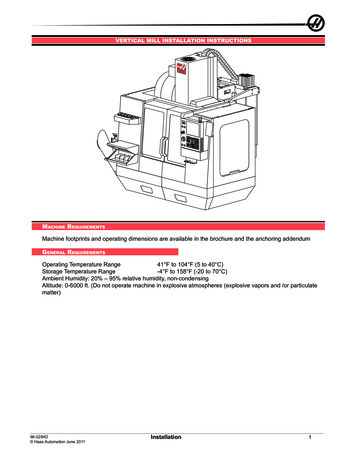
A general picture Screenshots of a VDEInitialequilibrium375 msWall Contact635 msThermal QuenchC. F. Clauser - TSD Workshop - Aug '19678 msMax Vertical Force700 msLCFS disappears5
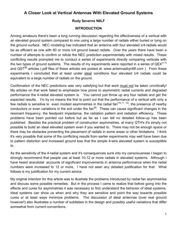
A general picture Some global quantities vs. timePlasma Temperature (eV)410(a)Plasma and Wall Currents 5510-1100.40.50.6time (s)0.700.4151.50.50.6time (s)0.700.4(d)30310Total Vertcal Force (MN)403.5122Z-magnetic Axis (m)0.5C. F. Clauser - TSD Workshop - Aug '190.6time (s)0.700.40.50.60.7time (s)6
Vertical force and halo currents𝑧̂ 𝐅D 𝑧̂ EFGHHGI𝐉 𝐁 d𝑉 EFGHHGI 𝐽@ 𝐵 𝐽 𝐵@ d𝑉The 𝐽@ 𝐵 à due to toroidal induction.The 𝐽 𝐵@ à due to halo currents.Can we increase the halo current in order to increase the total vertical force?In 2D simulation we initiate the TQ by increasing the thermal conductivity 𝜅- . We can do it indifferent ways: Varying the thermal conductivity magnitude and profile. Varying the temperature at the boundary.We generated a series of cases with different halo currents to analyze their effects.Basically, in the open field line (halo) region:higher temperature à lower plasma resistivity à higher currents.C. F. Clauser - TSD Workshop - Aug '197
I. Uniform post-TQ 𝜅Dependance of post-TQ temperature on 𝜿- values𝜅 1𝑇P 0.17 eV Smaller 𝜅- values à higher post-TQ 𝑇G . Halo region is naturally formed after the TQ. Changing k in this way has only small effect on open-field-line temperature.C. F. Clauser - TSD Workshop - Aug '198
I. Uniform post-TQ 𝜅Effect of varying 𝜿 on global plasma parameters Smaller 𝜅- values à higher post-TQ 𝑇G à slower CQ.Slower CQ à slower upward motion.Larger vertical forces for high 𝑇G .Only small dependence of maximum halo current magnitude on 𝜿 ( 1 MA)C. F. Clauser - TSD Workshop - Aug '199
I. Uniform post-TQ 𝜅Effect of varying 𝜿 on global plasma parameters Smaller 𝜅- values à higher post-TQ 𝑇G à slower CQ.Slower CQ à slower upward motion.Larger vertical forces for high 𝑇G .Only small dependence of maximum halo current magnitude on 𝜿 ( 1 MA)We select the case 𝑻𝒆 𝟑𝟎 eV as a referenceC. F. Clauser - TSD Workshop - Aug '1910
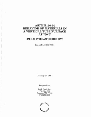
II. Different post-TQ 𝜅- profilesEffect of varying 𝜿 profiles on post-TQ 𝑻𝒆 and halo current.0.3(a)(b)300.25Te (eV)κ0.20.150.120100.05Sep.0456R (m)78045678R (m) Compare k constant, increasing, or decreasing in radius k decreasing in radius leads to largest Te on open field lines è halo currentC. F. Clauser - TSD Workshop - Aug '1911
II. Different post-TQ 𝜅- profilesEffect of varying 𝜿 profiles on post-TQ 𝑻𝒆 and halo current0.3(a)(b)300.25Te (eV)κ0.20.150.120100.05Sep.0456R (m)78045678R (m) Compare k constant, increasing, or decreasing in radius k decreasing in radius leads to largest Te on open field lines è halo current To increase even more the halo current, we increased the boundarytemperature from 0.17 eV to 3 eV.C. F. Clauser - TSD Workshop - Aug '1912
II. Different post-TQ 𝜅- profilesEffect of varying 𝜿 profiles on global plasma parameters k decreasing with radius leads to slower CQ and larger halo current. Increasing boundary 𝑇G strength these effects. Total vertical force largely unaffected.C. F. Clauser - TSD Workshop - Aug '1913
II. Different post-TQ 𝜅- profilesEffect of varying 𝜿 profiles on global plasma parameters k decreasing with radius leads to slower CQ and larger halo current. Increasing boundary 𝑇G strength these effects. Total vertical force largely unaffected.C. F. Clauser - TSD Workshop - Aug '1914
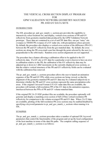
Comparison and breakdown of forcesConstant k, .17 eV Te BCVertical Force (MN)40Decreasing k, 3 eV Te r2020151510105500.620.640.660.68time Bφr0.640.660.680.70.720.74time (s) Larger halo current had larger JrBj term, as expected, but, it is offset by a stronger reduction in the JjBr contribution. Total vertical force is almost unaffected by magnitude of halo current.C. F. Clauser - TSD Workshop - Aug '1915
Comparison and breakdown of forcesRelationship between inductive toroidal and poloidal halo wall forcesIt is possible to write the total force on the vessel as (*)][I𝐹F 𝐹FZ[\ 𝐹F 𝐹 The halo formation after the TQ occurs in a timescale (𝜏 10 ms) much shorterthan the dissipation time of wall currents (𝐿 𝑅 235 ms). Thus, the vessel “acts”as an almost perfect conductor during this process.Therefore, the poloidal flux outside the vessel does not change implying that 𝐹 and, as a consequence 𝐹F , remains constant.(*) Wesson, Tokamaks (Oxford Press, 2011).C. F. Clauser - TSD Workshop - Aug '1916
Comparison and breakdown of forcesHow toroidal contribution offsets the poloidal halo force?The halo region formationproduces a current densitycentroid displacementC. F. Clauser - TSD Workshop - Aug '1917
SummaryWe performed a series of 2D-VDE simulations varying the post-TQ thermal conductivity and the post-TQ temperature boundary conditionin order to cover a wide range of cases. We found that vertical wall force shows a dependence on post-TQ temperature. Slower CQ generally lead to larger vertical forces: for CQ times short compared to vessel L/R time. However, the presence of halo currents can modify this scaling. We showed that vertical wall force shows a very weak dependence on halo currentmagnitude. Toroidal contribution to the total force compensates the halo contribution.C. F. Clauser - TSD Workshop - Aug '1918
Moving forward We have already started 3D non-linear simulations. kink instabilities and sideways force. Implementing a more realistic wall with anisotropic wall resistivity. Working in coupling M3D-C1 results with the CARRIDI engineering code (actualvessel).C. F. Clauser - TSD Workshop - Aug '1919
Extra slides C. F. Clauser - TSD Workshop - Aug '1920
Poloidal unstructured meshFull MeshClose-up of Plasma RegionC. F. Clauser - TSD Workshop - Aug '1921
3D Extended MHD Equation in M3D-C1¶n Ñ (nV ) Ñ! DnÑn S n¶t¶A11 -E - ÑF, B Ñ A, J Ñ B, Ñ ! 2 ÑF -Ñ ! 2 E¶tRR¶VnM i ( V ÑV ) Ñ p J B - Ñ Π i S m¶tm æ ¶V1öE V B ( R c J B - Ñpe - Ñ Π e ) - e ç e Ve ÑVe SCDnee è ¶tøZjR3 é ¶peJ é35 peùùæ J ö Ñ pV pÑ V ÑpÑn R Ñ()eeecúç : Π e - Ñ q e QD SeEêúê2 ë ¶tne ë 22 nè ne øûû3 é ¶più Ñ pV()iúû - piÑ V - Π i : ÑV - Ñ qi - QD SiE2 êë ¶tR c h neJ ,Π i - µ éëÑV ÑV † ùû - 2( µc - µ )(Ñ V )I Π Gi VΠ e (B / B 2 )Ñ éëlhÑ ( J B / B 2 ) ùû ,Blue terms are 2-fluid terms.Ve Vi - J / neq e,i -k e,i ÑTe ,i - k !Ñ!Te ,iQD 3me ( pi - pe ) / ( M it e )NOT reduced MHD.C. F. Clauser - TSD Workshop - Aug '1922
Using the appropriate L/R time Applied a constant loop voltage atthe domain boundary. Without any plasma, the systembehaves as a basic LR-circuit.C. F. Clauser - TSD Workshop - Aug '19" # 235 ms23
𝜅 𝜅- effect on the open field line 𝑇G Inside the plasma: the post-TQ temperatureprofile is mostly determined by 𝜅𝑇bc d: e𝜅-bc Outside the plasma: 𝜅 links the plasmatemperature with the boundary condition.Assuming 𝑇fgh 𝑒 djk , very simplified 𝛼 𝛼 𝜅 𝜅- dependence can be derived.C. F. Clauser - TSD Workshop - Aug '1924
Poloidal halo currents patterns for both casesConstant k, .17 eV Te BCDecreasing k, 3 eV Te BCPoloidal halo currents can follow different paths and generate a complex pattern.C. F. Clauser - TSD Workshop - Aug '1925
Current breakdownConstant k, .17 eV Te BCToroidal currents (MA)16Decreasing k, 3 eV Te smaVessel8 PlasmaVesselHaloPlasmaVesselHaloPlasmaVesselHalo Halo(pol)VesselHalo Halo(pol)Halo(pol)Wall6 HaloHalo )PlasmaPlasmaPlasmaVesselPlasmaVessel8 llVesselHalo WallHalo(pol)Wall6 40.660.680.70.720.74-20.620.640.66time (s)0.680.70.720.74time (s)C. F. Clauser - TSD Workshop - Aug '1926
Halo Plasma Vessel Halo Halo (pol) Plasma Vessel Halo Halo (pol) Wall Plasma Vessel Halo Halo(pol) Wall Wall-pos Plasma Vessel Halo Halo(pol) Wall Wall-pos Wall-neg-2 0 2 4 6 8 10 12 14 16 0.62 0.64 0.66 0.68 0.7 0.72 0.74 time (s) Plasma (b) Plasma Vessel Plasma Vessel Halo Plasma Vessel Halo Wall Plasma Vessel