Transcription
IRC Wall Bracing:A Guide for Builders, Designers and Plan ReviewersWith Supplemental Information on Appropriate Use of Foam SheathingThe requirement for bracing conventional wood frame dwellings is not new. Foryears, homes have been braced using a variety of techniques that have withstoodthe elements over time. Conventional wood frame dwellings must adequately braceagainst lateral (racking) forces due to wind and earthquakes. To achieve thisstructural safety objective, several wall bracing options and requirements areoffered prescriptively in the International Residential Code (IRC) Section R602.10Wall Bracing section, although the number of options and requirements has createdconfusion instead of a “simple-to-use” prescriptive code.The main objective of this guide is to provide designers, code officials and builders a basicunderstanding of how to apply the IRC bracing provisions for code-compliant dwellings. A secondobjective is to demonstrate how the IRC bracing provisions can be used to create maximum valuein a diverse housing market.The guide is divided into four stand-alone sections; depending on your specific needs, refer to therelevant section: Section 1: Basic Concepts for Code-Compliant Wall BracingSection 2: IRC Wall Bracing RequirementsSection 3: ‘Beyond Code’ Bracing SolutionsSection 4: Wall Bracing Options for Foam-Sheathed Wall SystemsFor additional information and design details, refer to the Supplement toIRC Wall Bracing Guide Design Examples.Foam Sheathing Coalition (FSC)Copyright 2006Version 1.0
IRC Wall Bracing: A GuidePage iTable of ContentsSection 1: Basic Concepts for Code-Compliant Wall Bracing . 1Why is Wall Bracing Needed? . 1How does Wall Bracing Work? . 1When Should I Consider Wall Bracing?. 2Definitions and Terms . 2Section 2: IRC Wall Bracing Requirements . 6Design Scope Limitations . 6Wall Bracing Methods . 6Applying the Code: Calculating the Amount of Bracing . 9Special Considerations. 13Special Connection Requirements for Braced Wall Panels .13Large Wall Openings & Prescriptive Narrow Braced Wall Panels.13Garage Openings and Similar Applications .13Fitting Large Openings within Code-Compliant Braced Wall Lines .15Applying the Code: Step by Step. 17Section 3: ‘Beyond Code’ Bracing Solutions .18Custom Engineered Solutions . 18Engineered Standard Solutions (Examples & Concepts) . 18Partial Credit for Narrow Braced Wall Panels.18Interior Partition Walls as a Bracing Method .19Reduce Bracing Amount for Braced Wall Line Spacing 35’ .19Allowance for Bracing Transfer.20Allowance for 4’ limit for Offsets within a Braced Wall Line .21Proprietary Bracing Products . 21Section 4: Wall Bracing Options for Foam-Sheathed Walls .22Why Use Foam Sheathing?. 22Meeting Energy Code Requirements . 23Which Bracing Method(s) to use with Foam Sheathing? . 24Examples . 26Interfaces between Materials . 29Additional References .30Design Tools and Resources:. 30Metal Bracing: . 30Proprietary Bracing Products: . 30Attachment A: Wall Bracing Design and Plan Check Worksheet .31
IRC Wall Bracing: A GuidePage iiList of Tables and FiguresTablesTable 1: Common IRC Bracing Methods and Requirements .7Table 2: Minimum Braced Wall Panel Lengths for Continuous Wood Structural Sheathing BracedWalls .8Table 3a: Minimum Wall Bracing Amounts .11Table 4: Effective Brace Lengths for Brace Segments 48" .19Table 5: Functions of Foam Sheathing in Above-Grade Residential Walls.23Table 6: Common IRC Wall Bracing Methods using Foam Sheathing .24FiguresFigure 1: Wall Bracing and Racking Forces.1Figure 2: Braced Wall Line Offset Limitations .4Figure 3: Use of Interior Braced Wall Lines .4Figure 4: Examples of Bracing Methods .5Figure 5: Corner Framing for Continuous Structural Sheathing.9Figure 6: Bracing Options for Garage Door and other Large Openings in a Braced Wall Line .14Figure 7: Example of Portal Frame Garage Opening Construction (HUD, 1998) .15Figure 8: Limits for Large Openings in Braced Wall Lines .16Figure 9: Bracing Transfer .20Figure 10: Illustration of Bracing Methods with Foam Sheathing .25
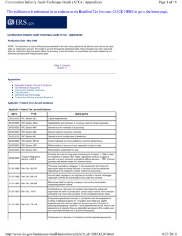
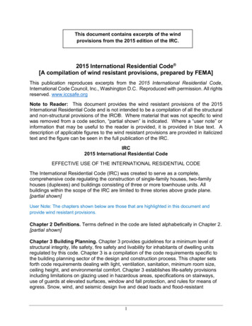
IRC Wall Bracing: A GuidePage 1Section 1: Basic Concepts for Code-Compliant Wall BracingWhy is Wall Bracing Needed?Wall bracing provides racking resistance against horizontal (lateral) racking loads from wind andearthquakes and prevents the wall studs from distorting in the plane of the wall (racking) in“domino fashion” and, thus, prevents building collapse. As shown in Figure 1, racking loads on abuilding are considered to act separately in two perpendicular plan directions (i.e., N-S and E-Wor front-rear and left-right). At least two wall lines parallel to each plan direction (and onopposite sides of the building) must be designed to resist potential racking loads.Figure 1: Wall Bracing and Racking ForcesHow does Wall Bracing Work?When bracing a wall, code-compliant bracing elements or “braced wall panels 1 ” are located inrequired amounts on wall lines that are required to resist racking loads, known as “braced walllines”. For simplicity, building codes have developed prescriptive bracing strategies that look onlyat designated “braced wall lines” and individual “braced wall panels” on those braced wall lines;in reality, walls act as a system in resisting racking forces, where nearly every component andwall segment provides some racking resistance.The entire building - wall, floor and roof assemblies - interacts to distribute racking loads. Forexample, standard interior partition walls also contribute to racking resistance, although the IRCdoes not explicitly consider their contribution. In addition, roof and floor diaphragms helpdistribute racking loads from walls with less bracing to those with more bracing. By consideringonly designated braced wall lines without considering the building system as a whole, the IRCbracing provisions generally result in conservative solutions. For example, if an individual bracedwall line (e.g., garage opening wall) is deemed ‘non-compliant’ when strictly applying the IRC, it1See Definitions and Term, page 2 for details
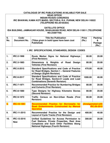
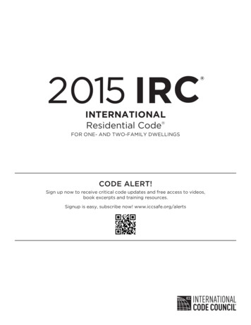
IRC Wall Bracing: A GuidePage 2may actually be acceptable from the standpoint of the entire building system. To make practicaluse of these building system realities requires solutions that go beyond the simple assumptionsthat a prescriptive code is based upon. Refer to Section 3: ‘Beyond Code’ Bracing Solutions andthe Additional Reference section for additional support and resources.Each braced wall line requires different amounts of bracing depending on the individual share ofthe racking load acting on the building as a whole (Figure 1). The amount of bracing required fora given wall line depends on:Design FactorCommentThe design wind orearthquake load (magnitudeof hazard).The size of the building andhow many stories aresupported by a braced wallline.Buildings in higher hazard areas with large design wind speeds orearthquake ground motions experience greater potential rackingload.Walls supporting multiple stories have greater racking loads thanthose supporting only a roof. Lower story walls serve to resist anaccumulation of lateral load from upper story levels that must bepassed down to the foundation and then to earth, in much the sameway that gravity (vertical) loads have a load path.For buildings that have widely-spaced wall lines and large interioropen areas, the racking load shared by each wall line is increasedrelative to a building that has many closely-spaced wall lines in eachplan direction.The method of bracing will determine how much bracing is needed.Some methods allow for less bracing and narrower braced wallpanels in comparison to other methods that require more bracingand wider braced wall panels to achieve equivalent performance(i.e., racking resistance meeting or exceeding racking load).The spacing between bracedwall lines.The type or method of wallbracing used (strength ofbrace).When Should I Consider Wall Bracing?The design factors (see above) affect the amount of space available on a given wall and thequantity when placing windows, doors and other non-structural sheathing products such asinsulating foam sheathing.Always consider wall bracing as early as possible in the design process.In the planning stages, a simple plan adjustment often makes the difference between an efficient,code-compliant plan and one that is inefficient or non-compliant. In some cases, an engineeredsolution may be required where the IRC prescriptive solutions are insufficient for the architecturalrequirements. Refer to Section 3: ‘Beyond Code’ Bracing Solutions for additional support.Definitions and TermsThe following concepts and definitions are fundamental to understanding and applying the IRCbracing requirements R602.10.Braced Wall Line (R602.10.1) – Walls that are braced to resist racking are known as bracedwall lines. Essentially all exterior walls are considered to be braced wall lines and arerequired to be properly braced with braced wall panels. Although not always required,interior walls may also be used as braced wall lines. A braced wall line can have limitedoffsets as shown in Figure 2 and still be considered a single braced wall line. When an offsetdoes not comply with those limits (i.e., offset exceeds 4’ or 8’ in total), the wall lines toeither side of the offset are required to be considered separate braced wall lines. In this
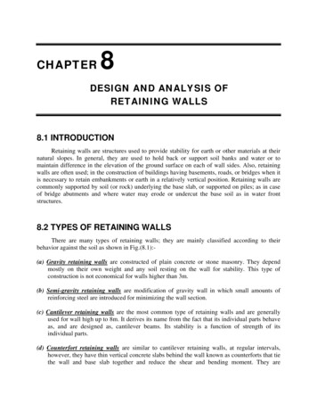
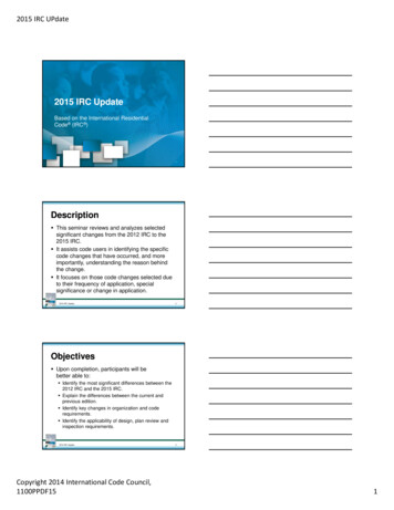
IRC Wall Bracing: A GuidePage 3manner, offsets can affect braced wall panel location and, thus, the layout of openings forwindows and doors in a series of braced wall lines on a given building side (elevation).Braced Wall Line Spacing (R602.10.1.1) – Braced wall line spacing establishes the amount ofracking load that must be resisted by the two or more parallel braced wall lines in each plandirection (see Figure 1). The racking load must be resisted by incorporating an adequateamount of braced wall panels in each braced wall line. Therefore, bracing amounts aredependent on the spacing between parallel braced wall lines (see Figure 1). Thisconsideration influences the space that is available for wall openings on exterior walls, whichmay require using interior braced wall lines to help share the bracing load (e.g., reduce thebraced wall line spacing) as shown in Figure 3. In Section 2 of this guide, minimum requiredbracing amounts have been tabulated based on braced wall lines spaced apart by 35’ up to amaximum 50’ as permitted by the IRC. :The interior braced wall line in Figure 3 is subject to the same braced wall panellocation requirements that apply to exterior braced wall lines. While the amount ofbracing required should be determined using the length of the wall as though it extendsentirely between opposite sides of the building as shown in Figure 3, the interiorbraced wall line itself need not extend the entire distance. Determination of bracingamount is addressed in Section 2 of this guide.Braced Wall Panel (R602.10.1) – A braced wall panel is a section of a braced wall line that isbraced with a code-compliant bracing method (e.g., let-in brace, a wood structural panel, orother bracing methods) (See Figure 4). Braced wall panels must meet minimum widthrequirements (length of wall covered) to count towards the required bracing amounts. Theminimum widths required for braced wall panels of the various bracing methods constrain thelayout and spacing of wall openings in a code-compliant braced wall line. While braced wallpanels that are narrower than allowed still contribute to bracing, this contribution may onlybe considered through an engineered design or supplemental solutions. (See Section 3:‘Beyond Code’ Bracing Solutions)Braced Wall Panel Location (R602.10.1) – In addition to being used to meet minimum bracingamounts, the location of braced wall panels on braced wall lines must meet additionalconstraints (see Figure 4):(1) Braced wall panels must be spaced no greater than 25’ OC along a braced wall line,and.(2) Braced wall panels must begin no more than 12.5’ from the end of a braced wall line(usually defined by an inside or outside building corner). : For the continuous wood structural sheathing method (IRC Section R602.10.5), aminimum 2’ panel must be located on both sides of corners at the ends of thebraced wall line (see Figure 4c). :Notice that Figure 4c shows that different bracing methods may be used ondifferent braced wall lines of a given building. In addition, certain bracing methodsmay be substituted for another within a portion of given braced wall line. Thisconsideration is important for design flexibility to create code-compliant buildingsthat maximize value of other building objectives (e.g., cost-effectiveness, energyefficiency, weather-resistance, etc.). Additional guidance on this topic is providedas appropriate in later sections.
IRC Wall Bracing: A GuidePage 4Figure 2: Braced Wall Line Offset LimitationsFigure 3: Use of Interior Braced Wall Lines
IRC Wall Bracing: A GuidePage 5Figure 4: Examples of Bracing Methods
IRC Wall Bracing: A GuidePage 6Section 2: IRC Wall Bracing RequirementsDesign Scope Limitations This guide is limited to the following use conditions:International Residential Code, 2000 through 2006 Editions 2One- and two-family dwellings 3Conventional wood frame constructionWind speed of less than 100 mph (gust) per IRC Section R301.2 inSeismic Design Categories A/B (See Table 3a)Wind speed of less than 110 mph (gust) per IRC Section R301.2 inSeismic Design Category C (See Table 3b)Seismic Design Category (SDC) of A/B/C per IRC Section R301.23By limiting the scope to lower wind and seismic conditions, the IRC bracingprovisions are greatly simplified, but still cover the majority of conditionsin the United States. To identify your specific seismic and wind speedlocation, see (A)Figure R301.2(2) Seismic Design Categories and (B)Figure301.2(4) Basic Wind Speeds for 50 year Mean Recurrence Interval inIRC2003.While this guide addresses principles that also apply to buildings in morehazardous areas, the exact bracing requirements are different. Refer toadditional requirements in the IRC for conditions outside the scope of thisguide.Wall Bracing MethodsTable 1 summarizes the most commonly used IRC bracing methods.Remember that these are the basic ‘bracing building blocks’ – a varietyof these methods may be used to design and construct a code-compliantbraced wall or building.2This guide is primarily based on IRC 2003 but is also applicable to IRC 2000 provided requirements forinterior braced wall lines and braced wall line spacing are ignored. Any additional provisions of the IRC 2006are specifically noted in this guide.3Townhouses in SDC C are excluded from this guide because additional seismic design limitations in IRCSection R301.2.2 apply and are outside the scope of this guide. However, those limitations may be waived bylocal code amendment or by approved design given that the same structural and bracing requirements mustbe satisfied regardless of a dwelling’s classification as single-family detached or single-family attached(townhouse) construction. In fact, the limitations of IRC Section R301.2.2 for building irregularities (constraintson configuration) do not apply to conventional construction in IBC Section 2308 until the next higher seismicdesign category, SDC D.
IRC Wall Bracing: A GuidePage 7Table 1: Common IRC Bracing Methods and Requirements(based on IRC Section R602.10.1, R602.10.3-6)Bracing MethodaBraced Wall Panel Minimum WidthbTRADITIONAL BRACING METHODSMETHOD 1: 1x4 wood let- Brace angle must be at least 45 degrees and not more than 60 degrees from horizontal. : Each such brace counts as a “braced wall panel”. Approved metal braces should bein brace or approvedspecified and installed in accordance with the manufacturer’s data and code evaluationmetal bracereport48” minimumMETHOD 3: Wood : Braced wall panels that are 48“wide or more count toward required bracingstructural panelsamounts; multiple sheathing panels may be used to form an individual braced wallMETHOD 4: Fiberboardpanel.96” minimum (single side)METHOD 5: Gypsum48” minimum (both sides)board : For ‘both sides’ application, braced wall panels 48” wide or more count towardrequired bracing amounts; for ‘single side’ application, braced wall panels 96”wide ormore count toward required bracing amount in accordance with actual length.SUPPLEMENTAL BRACING METHODS24” and greater – see Table 2 (braced wall panels complying with minimum widthContinuous woodrequirements of Table 2 count toward required bracing amount and vary in accordancestructural panelwith the height of an adjacent window or door opening)sheathing (R602.10.5)cAlternate braced wallpanels (R602.10.6)(Section R602.10.6.1 in IRC2006)R602.10.6.2 Alternatebraced wall paneladjacent to a door orwindow opening(Portal Frame)(IRC 2006 only) : Similar to Method 3 but requires all sheathable areas of a braced wall line to besheathed, including areas above and below wall openings; minimum 2’ wide panels arerequired at each end of the braced wall line at corners. See Figure 4c and Figure 5.32” minimum : Each 32” alternate braced wall panel may be substituted for a 48” braced wallpanel of another bracing method. : Similar to Method 3 with additional sheathing nails but requires using hold-downbrackets at each end of the braced wall panel directly anchored to the foundation;limited to 1-story and first floor of a 2-story application)16” minimum (supporting one story); 24” minimum (supporting two stories) : Each such panel may be substituted for a minimum 48” braced wall panel of anyone of the other bracing methods listed above. : This method requires special wall framing details, connection hardware, andsheathing nailing patterns which are addressed in the IRC 2006. A variation of thismethod without using hold-down brackets is also found in Section R602.10.5 of the IRC2006 (footnote ‘c’ of Table R602.10.5) – also refer to footnote ‘c’ below.Notes:a. Refer to IRC Section R602.10.3, R602.10.5, and R602.10.6 for important installation requirements,material thickness requirements, and details related to fastening for each bracing method.b. Refer to Section 3: ‘Beyond Code’ Bracing Solutions for alternative minimum braced panel widths.c. Note that the IRC 2003 and 2006 versions of Section R602.10.5 include language not found in the IRC2000 which requires correction and/or clarification. In particular, language implying that “all walls”of a building must be continuously sheathed should be deleted for reason of inconsistency with theoriginal data substantiating the approval of this method in the IRC 2000. Second, the amount ofsheathing required at the ends of such a fully-sheathed wall should be clarified as 2’ minimum lengthof full-height structural sheathing (applied to both sides of the corner per Figure R602.10.5 or Figure5 in this guide). These same concerns also apply to the use of the portal framing method of SectionR602.10.6.2 of the IRC 2006 and as modified in footnote ‘c’ of Table R602.10.5 (or Table 2 of thisguide). At the time of this writing, several states and localities have already made such correctionsor clarifications through their local code adoption processes and several similar ICC code proposalsare pending consideration in the 2006/2007 code development hearing cycle.
IRC Wall Bracing: A GuidePage 8Table 2: Minimum Braced Wall Panel Lengths for Continuous Wood Structural Sheathing Braced Walls(based on IRC Table R602.10.5)Largest Adjacent Opening Minimum Braced Wall Panel Length (inches)Height (inches)8-ft Wall9-ft Wall10-ft 30692627306625273063242730Notes:a. ‘N/A’ indicates that opening height exceeds limits permitted for usewith IRC Section R602.10.5.b. For continuous structural sheathed braced wall lines containing only garage openingsand which support a light frame roof only, braced panel widths shall be permitted tohave a 4:1 height-to-width ratio (with height being measured from the bottom to thetop of the braced wall panel). Minimum panel width shall not be less than 24 inches. : The 3 psf roofing dead load limit in the related IRC Table R602.10.5 footnote isnot intended to apply in SDC A/B/C. Actually, heavier roofing is a benefit in regionswhere wind governs wall bracing design.c. Walls on either or both sides of openings in garages shall be permitted to bebuilt in accordance with Section R602.10.6.2 and Figure R602.10.6.2 (IRC 2006)except that a single bottom plate shall be permitted and two anchor bolts shallbe placed at 1/3 points. In addition, tie-down devices shall not be requiredand the vertical wall segment shall have a maximum 6:1 height-to-width ratio(with height being measured from top of header to the bottom of the sillplate). This option shall be permitted for the first story of two-storyapplications in Seismic Design Categories A through C. : The requirement for “fully-sheathed dwelling” in the related IRC 2006Table R602.10.5 note is not required in the note above for reasons given innote ‘c’ of Table 1.
IRC Wall Bracing: A GuidePage 9Figure 5: Corner Framing for Continuous Structural Sheathing(Based on IRC Figure R602.10.5)Applying the Code: Calculating the Amount of BracingThe minimum required wall bracing amounts for commonly-used bracing methods are shown inTables 3a and Table 3b.ooTable 3a applies to typical hazard conditions found in most regions of the UnitedStates.Table 3b addresses a moderate hazard condition. These tables are based on TableR602.10.1 of the IRC plus some “user-friendly” improvements such as precalculating bracing amounts for:1) Permitted braced wall line spacings, and2) Continuous structural panel sheathing method of Section R602.10.5.Refer to Section 1 (page 2) of this guide for important information on thefollowing definitions: braced wall line, braced wall panel, braced wall panellocation, and braced wall line spacing. These definitions involve concepts andrequirements that are very important to a code-compliant and efficient applicationof required wall bracing amounts on a given braced wall line or building plan.
IRC Wall Bracing: A GuidePage 10For many braced wall lines, Method 1 let-in bracing may be the simplest method to use in terms ofdetermining and applying required bracing amounts. The amount of bracing is simply determinedby the spacing of code compliant 1x4 wood let-in or approved metal braces along a braced wallline (see Figure 4a). As shown in Table 3a and Table 3b, the spacing of Method 1 braces along abraced wall line decreases from 25’OC as the spacing between braced wall lines increases beyond35’OC. This requirement increases the racking strength of a Method 1 braced wall line to offsetthe added racking load from a greater than 35’ spacing between braced wall lines (refer to IRCSection R602.10.1.1, exception statement). Also note that a Method 3 brace may be used in placeof any required Method 1 brace on a given braced wall line based on the principle of equivalence(i.e., Method 3 panel brace is at least as strong as a Method 1 let-in brace). Finally, the use ofMethod 1 bracing is limited to one- and two-story construction in Table 3a and one-storyconstruction in Table 3b.For the other common bracing methods featured in Table 3a and Table 3b, bracing amounts aregiven as the minimum percentage of braced wall line length that must be braced by codecompliant braced wall panels (see Table 1 and Figure 4b and c).To determine the minimum required length of bracing for a given braced wall line, use thefollowing simple equation:Minimum Required Length of Braced Wall Panels [Braced wall line length] x [(Percentage from Table 3A or B)/100]Eq. 1Example:Given:25% amount of bracing required for a braced wall line (Table 3a or 3b)32’ braced wall line lengthSolution: [32’] x [25% / 100] 32’ x 0.25 8’Therefore, a total of 8’ of braced wall panels is the minimum required amount of bracing forthis example braced wall line (i.e., two 4’ braced wall panels). Depending on braced wallpanel location on the braced wall line, an additional braced wall panel may be required.
IRC Wall Bracing: A GuidePage 11Table 3a: Minimum Wall Bracing Amountsfor Seismic Design Categories A/B and Wind Speed of 100 mpha,b,c(based on IRC Table R602.10.1 and Sections R602.10.1.1, R602.10.5, and R602.10.6)BracedWall LineConditionSupportingRoof OnlySupportingRoof plusOne StorySupportingRoof plusTwoStoriesBracedWallLineSpacing(feet) 35404550 35404550 36%35%40%45%50%Method ContinuousStructuralSheathingdCase ACase 3%15%17%19%20%23%26%29%Notes:NP not permitteda. Interpolation between braced wall line spacing amounts is permissible.b. Table applies to stud walls up to 10’ tall. For walls 12’ tall, multiply bracing amounts by 1.2 (IRCSection 301.3).c. For Method 1 bracing, braces shall be located no more than 12.5’ from the ends of a braced wall lineand shall be spaced along a braced wall line as shown in the table. For the other methods, bracedwall panels shall not be spaced greater than 25’ OC and also shall be located no more than 12.5’from the ends of a braced wall line. However, for R602.10.5 continuous structural panel sheathing, aminimum 2’ length of full-height sheathing is required at the corners per Figure 4c. Refer to Table1 for minimum lengths of individual braced wall panels and other requirements for each bracingmethod.d. Case A applies to braced wall lines with maximum opening height not exceeding 86” (8’ stud walls),95” (9’ stud walls) or 102” (10’ stud walls). Case B applies to braced wall lines with maximumopening height not exceeding 65” (8’ stud walls), 74” (9’ stud walls) or 80” (10’ stud walls).Themaximum opening height in a continuous structural sheathed braced wall line is the rough openingwith the largest height measured from the bottom of the rough opening to the top of the roughopening.e. Method 5 (one side) bracing amounts are doubled relative to Method 5 (both sides) to account forthe difference in strength of the two applications of Method 5 bracing. This consideration wasoverlooked in development of the IRC wall bracing provisions, but is included in the IBC Section 2308wall bracing provisions.
IRC Wall Bracing: A GuidePage 12Table 3b: Minimum Wall Bracing Amountsfor Seismic Design Category C and Wind Speed of 110 mpha,b,c(based on IRC Table R602.10.1 a
IRC Wall Bracing: A Guide Page 3 manner, offsets can affect braced wall panel location and, thus, the layout of openings for windows and doors in a series of braced wall lines on a given building side (elevation). Braced Wall Line Spacing (R602.10.1.1) – Braced wall line spacing establishes the amount of racking load t