Transcription
8Drawing Walls, Windows, &DoorsThe Architct menu in the Edit menu combines the three most basicdrawing elements under a single menu. Architct includes options fordrawing 2-line, 3-line, and 4-line walls as well as windows and sixdifferent door styles, all with a variety of customizable options.With a single choice from the Architct menu, you can begindrawing walls whose intersections can be cleanedautomatically. Windows, doors, and other wall openings canthen be inserted with just a few clicks and, if necessary,removed just as easily.In this chapter:Drawing 2-line, 3-line,and 4-line wallsDrawing andremoving doorsDrawing andremoving windowsDrawing andremoving openingsin walls
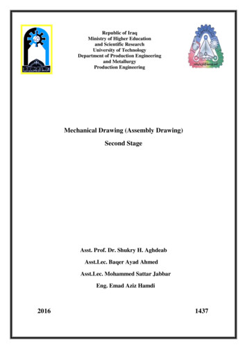
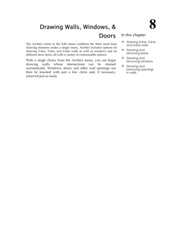
178 CHAPTER 8: DRAWING WALLS, WINDOWS, & DOORSDrawing WallsWalls can be drawn by simply toggling on the Walls option in the Architct menu.DataCAD automatically cleans wall intersections, including the last intersectionwhere the first and last walls drawn meet.You can draw 2-line walls using the 2LnWalls option, 3-line walls using the3LnWalls option, or 4-line walls using the 4LnWalls option. Two line walls drawan inside and an outside line, 3-line walls add a centerline, and 4-line walls addtwo cavity walls. The 2LnWalls, 3LnWalls, and 4LnWalls toggles are mutuallyexclusive; when one is toggled on, the others are automatically toggled off.Outside wall2LnWallInside wall with Hilite3LnWallCenter line4LnWallCavity wallFigure 8.1: DataCAD’s wall typesYou can also use the Walls option in the DCAD AEC macro to draw walls. ThisWalls option works the same way that Walls in the Architct menu does, althoughit does have fewer settings to customize wall display.To draw walls:1. Make sure Ortho is toggled on. Walls can only be drawn in orthographic,or plan, view; if you’re not already in plan view, click on Ortho in theProjection Pad or click Orthographic in the View pull-down menu.2. Go to the Edit menu in the Menu Window and click on Architct.Shortcut: Press ( ) to quickly toggle Walls on or off from anywhere in DataCAD.3. Click on Walls in the Architct menu to toggle it on; Wall is checked in theCreate pull-down menu, and you can now draw walls instead of lines.4. Click on 2LnWalls to draw 2-line walls, click on 3LnWalls to draw 3-linewalls, or click on 4LnWalls to draw 4-line walls.5. Set the wall attributes using the Hilite option along with Width for 2-linewalls, CntrLine for 3-line walls, and Exterior, Interior, and Cavity for 4line walls. See “More About Setting Wall Attributes” later in this chapter.
DRAWING WALLS 6. Select two points to draw a wall. When you do this, the line connectingthose two points becomes the outside wall, inside wall, center of the wall,or center of the wall cavity, depending on whether Outside, Inside,CntrWall, or CntrCvty is toggled on, respectively. Click on Outside todefine walls by the outside of the wall, click on Inside to define them bythe inside of the wall, click on CntrWall to define them by the center ofthe wall, or click on CntrCvty to define them by the center of the wallcavity. When drawing 2-line walls or 3-line walls, CntrWall and CntrCvtywork the same way. You can choose either option to create walls basedon the wall center.7. Click on Clean to automatically clean wall intersections as you draw yourwalls; click on Cap to cap wall ends as you draw your walls. You areprompted to “Select first end point of new line/wall”. For moreinformation on using Clean and Cap, see “More About Finishing Walls”later in this chapter.8. Click anywhere in the Drawing Area or use coordinate entry to startdrawing your walls. You are prompted to “Select next end point of newline/wall”.9. Move the cursor using your mouse and click again or use coordinateentry to specify the end of the first wall.10. Click anywhere on the inside or outside of the wall, depending on whatyou did in step 6. If you chose Outside, CntrWall, or CntrCvty in step 6,click anywhere on the inside of the wall; if you chose Inside in step 6,click anywhere on the outside the wall.11. Notice that your cursor is still connected to the end of your first wall. Youcan continue selecting wall end points, as you did in step 9; allintersections will be automatically cleaned.12. Finish drawing walls by right-clicking to disconnect your cursor from thewall, or clicking near the first endpoint of your first wall to close yourwall plan. Your cursor is automatically disconnected.Sometimes, you may need to fix wall intersections that didn’t clean properlywhen they were drawn. Use the Cleanup menu’s TIntsct, LIntsct, and XIntsctoptions to clean wall intersections. Use the Cleanup menu’s WeldLine and WeldWall options to mend openings in walls. See “Cleaning Wall Intersections” and“Welding Lines and Walls” in the “Editing Drawings” chapter.More About Setting the Width of WallsWhen toggling on the Walls option in the Architct menu, you are prompted for anew wall width. A wall width is the distance between the inside and outside wall.You can also change wall width anytime while drawing 2-line or 3-line walls.To change the width of walls to be drawn:1. Go to the Edit menu in the Menu Window and click on Architct.179
180 CHAPTER 8: DRAWING WALLS, WINDOWS, & DOORS2. Click on Width in the Architct menu. A value menu is displayed in theMenu Window. The Width option is not available when 4LnWalls istoggled on3. Use the value menu to enter a new width, or type a new width and press(Enter). DataCAD sets the new wall thickness and subsequent walls willbe drawn with that thickness. For more information on using valuemenus, see “Value Menus” in “The Drawing Board” chapter.More About Setting Wall AttributesYou can assign different attributes to outside or inside walls, including colors,linetypes, and line weights by using the Hilite option in the Architct menu. Otherattribute options apply only to 3-line or 4-line walls.To draw walls with either the outside or inside wall in a different color,linetype, or line weight:1. Go to the Edit menu in the Menu Window and click on Architct.2. Click on Hilite in the Architct menu. The Hilite menu is displayed in theMenu Window. You can only set Hilite options for either the inside wallor the outside wall; for example, you can’t assign a color to the outsidewall and a linetype to the inside wall.3. Click on Outside in the Hilite menu to highlight the outside of your walls.Click on Inside to highlight the inside of your walls.4. Click on Color to choose a highlight color, click on LineWgt to choose aline weight to highlight your walls with, or click on LineType to choose alinetype as a highlight.5. Right-click to return to the Architct menu.6. Begin drawing your walls. Notice that the color, linetype, or line weightattributes you set are applied as walls are drawn.To set attributes for the center line when drawing 3-line walls:1. Go to the Edit menu in the Menu Window and click on Architct.2. Click on CntrLine in the Architct menu. The CntrLine menu is displayedin the Menu Window. The CntrLine option is only displayed when3LnWalls is toggled on.3. Click on Color to choose a highlight color, click on LineWgt to choose aline weight to highlight your walls with, click on LineType to choose alinetype as a highlight, or click on Spacing to set the spacing for the centerline. The Spacing setting lengthens both the lines and the spaces in alinetype, so that the aspect ratio of the linetype is preserved.To set the distance from the exterior wall to the exterior cavity wall whendrawing 4-line walls:1. Go to the Edit menu in the Menu Window and click on Architct.
DRAWING WALLS 2. Click on Exterior in the Architct menu. A list of width values is displayedin the Menu Window.3. Use the value menu, or type a new value and press (Enter) to set theexterior wall thickness. For more information about how to use valuemenus, see “Value Menus” in “The Drawing Board” chapter.To set the distance from the interior wall to the interior cavity wall whendrawing 4-line walls:1. Click on Architct in the Edit menu.2. Click on Interior in the Architct menu. A list of width values is displayedin the Menu Window.3. Use the value menu, or type a new value and press (Enter) to set theinterior wall thickness.To set the attributes for the cavity wall when drawing 4-line walls:1. Click on Architct in the Edit menu.2. Click on Cavity in the Architct menu. The Cavity menu is displayed inthe Menu Window.3. Click on Width to set the width from the exterior cavity wall to theinterior cavity wall; click on Color to choose a color for cavity walls; clickon LineWgt to set the line weight of cavity walls; click on LineType to setthe linetype for cavity walls; click on Spacing to set the spacing for cavitywalls.More About Finishing WallsAs you saw in the tutorial in this manual, DataCAD always cleans theintersections of walls as you draw them, as long as you don’t disconnect yourcursor from the last wall you drew. For T intersections, you can toggle on Cleanin the Architct menu to automatically trim the interior wall lines as you draw thewalls so that your walls look continuous, without internal lines at corners.Sometimes you may need to fix wall intersections that didn’t clean properlywhen they were drawn. Use the Cleanup menu’s TIntsct, LIntsct, and XIntsctoptions to clean wall intersections. Use the Cleanup menu’s WeldLine and WeldWall options to mend openings in walls.Shortcut: Press (\) to toggle Clean on or off.The Cap option in the Architct menu can be toggled on to insert a wall cap orclosure on the end of a wall. When you draw walls, wall ends are automaticallycapped instead of remaining open.The Clean and Cap toggles are mutually exclusive; when one is toggled on, theother is automatically toggled off.181
182 CHAPTER 8: DRAWING WALLS, WINDOWS, & DOORSUsing Wall StylesYou can save wall styles for 2-line, 3-line, or 4-line walls with the wall attributesyou use most often, and then use them in any drawing file. The followingattributes are saved in a wall style: line color, linetype, line spacing, and line weight of wall lines. The Spacingsetting lengthens both the lines and the spaces in a linetype, so that the aspectratio of the linetype is preserved. whether you want to highlight the inside or outside line of your walls usingcolor, line weight, and linetype. wall widths and center line and cavity wall attributes.To save a new wall style:1. Go to the Edit menu in the Menu Window and click on Architct.2. Click on WallStyl in the Architct menu. The Wall Style Manager dialogbox is displayed.3. Click on SaveAs in the Wall Styles Available section at the bottom of thedialog box. Another small dialog box is displayed, prompting you toenter a new wall style name.4. Type a name for your new wall style, and press (Enter) or click on OK.The wall style is saved and now appears in the drop-down list in thebottom left corner of the dialog box.5. Click on OK to close the dialog box.To save changes to a wall style:1. Go to the Edit menu in the Menu Window and click on Architct.2. Click on WallStyl in the Architct menu. The Wall Style Manager dialogbox is displayed.3. Using the drop-down list in the Wall Styles Available section at thebottom of the dialog box, select the wall style you want to save changesto.4. Change wall settings as necessary.5. Click on Save in the Wall Styles Available section at the bottom of thedialog box. The wall style is saved with any changes you made to wallsettings.To use a wall style:1. Go to the Edit menu in the Menu Window and click on Architct.2. Click on WallStyl in the Architct menu. The Wall Style Manager dialogbox is displayed.3. Use the drop-down list in the Wall Styles Available section at the bottomof the dialog box to select the wall style you want to use. Wall settings inthe dialog box are changed to those of the wall style you selected.
DRAWING WALLS 4. Click on OK to close the dialog box.To delete a wall style:1. Go to the Edit menu in the Menu Window and click on Architct.2. Click on WallStyl in the Architct menu. The Wall Style Manager dialogbox is displayed.3. Use the drop-down list in the Wall Styles Available section at the bottomof the dialog box to select the wall style you want to delete.4. Click on Delete. The selected wall style is deleted.5. Click on OK to close the dialog box.To display the settings for a wall style:1. Go to the Edit menu in the Menu Window and click on Architct.2. Click on WallStyl in the Architct menu. The Wall Style Manager dialogbox is displayed.3. Use the drop-down list in the Wall Styles Available section at the bottomof the dialog box to select the wall style whose settings you want to view.Wall settings in the dialog box are changed to those of the wall style youselected.4. Click on OK to use those wall style settings and close the dialog box, orclick on Cancel to close the dialog box without changing wall settings.Cutting WallsYou can use CutWall in the Architct menu to remove sections of walls.To cut openings in walls using the mouse:1. Go to the Edit menu in the Menu Window and click on Architct.2. Click on CutWall in the Architct menu. The CutWall menu is displayed.3. Determine which layer your walls are on. If your walls are on a layerother than the active layer, click on LyrSrch to toggle it on. If LyrSrch isalready on, toggle it off and then back on again to choose your wallslayer. The layers in your drawing are listed in the Menu Window.4. Click on the layer your walls are drawn on.5. Select one side of the opening by clicking on a point on the wall or usingcoordinate entry to specify the exact coordinates. To choose a coordinateentry method, use the Input Mode option in the Utility pull-down menu.6. To select the other side of the opening, move the mouse along the walland click on any point or use coordinate entry. The wall is cut and thewall ends are capped automatically.If the wall opening is a result of adding a door or window when Cutout wastoggled off, you must use Erase in the Edit menu to erase
Using Wall Styles You can save wall styles for 2-line, 3-line, or 4-line walls with the wall attributes you use most often, and then use them in any drawing file. The following attributes are saved in a wall style: line color, linetype, line spacing, and line weight of wall lines. The Spacing setting lengthens both the lines and the spaces in a linetype, so that the aspect ratio of the .