Transcription
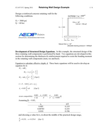
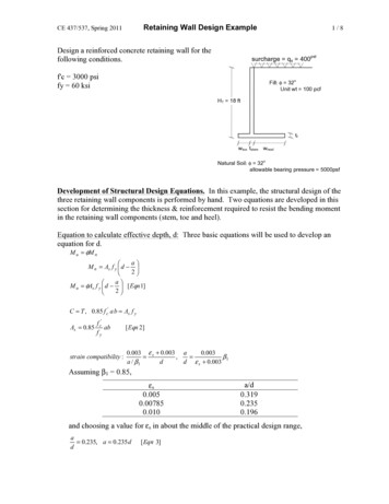
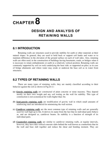
CHAPTER8DESIGN AND ANALYSIS OFRETAINING WALLS8.1 INTRODUCTIONRetaining walls are structures used to provide stability for earth or other materials at theirnatural slopes. In general, they are used to hold back or support soil banks and water or tomaintain difference in the elevation of the ground surface on each of wall sides. Also, retainingwalls are often used; in the construction of buildings having basements, roads, or bridges when itis necessary to retain embankments or earth in a relatively vertical position. Retaining walls arecommonly supported by soil (or rock) underlying the base slab, or supported on piles; as in caseof bridge abutments and where water may erode or undercut the base soil as in water frontstructures.8.2 TYPES OF RETAINING WALLSThere are many types of retaining walls; they are mainly classified according to theirbehavior against the soil as shown in Fig.(8.1):(a) Gravity retaining walls are constructed of plain concrete or stone masonry. They dependmostly on their own weight and any soil resting on the wall for stability. This type ofconstruction is not economical for walls higher than 3m.(b) Semi-gravity retaining walls are modification of gravity wall in which small amounts ofreinforcing steel are introduced for minimizing the wall section.(c) Cantilever retaining walls are the most common type of retaining walls and are generallyused for wall high up to 8m. It derives its name from the fact that its individual parts behaveas, and are designed as, cantilever beams. Its stability is a function of strength of itsindividual parts.(d) Counterfort retaining walls are similar to cantilever retaining walls, at regular intervals,however, they have thin vertical concrete slabs behind the wall known as counterforts that tiethe wall and base slab together and reduce the shear and bending moment. They are
Foundation EngineeringChapter 8: Design and Analysis of Retaining Wallseconomical when the wall height exceeds 8m. Whereas, if bracing is in front of the wall andis in compression instead of tension, the wall is called Buttress retaining wall.(e) Bridge abutments are special type of retaining walls, not only containing the approach fill,but serving as a support for the bridge superstructure.(a) GRAVITY WALLS(c) CANTILEVER WALL(b) SEMI-RAVITY WALL(e) BRIDGE ABUTMENT(d) COUNTERFORT WALLWsAAHHDredge lineDredge lineAnchor tie rodBBDCANTILEVER SHEET PILE WALL.(f) CRIB WALLSDPoint ofC rotationCANCHORED SHEET PILE WALL.(g) SHEET PILE WALLS.Fig.(8.1): Common types of retaining walls.2
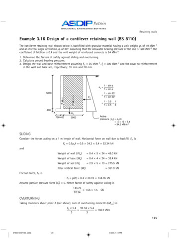
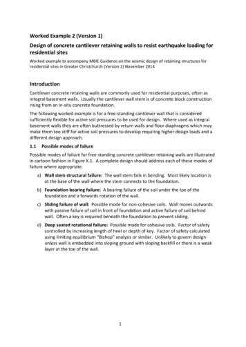
Foundation EngineeringChapter 8: Design and Analysis of Retaining Walls(f) Crib walls or coffer dams are cells or units to be filled with soil or built-up members of piecesof precast concrete or metal and are supported by anchor pieces embedded in the soil forstability.(g) Sheet pile walls are classified as; anchored and cantilevered sheet pile walls; each kind ofthem may be used in single or double sheet walls. Of these walls, only the cantileverretaining walls and the bridge abutments are mostly used at present due to their greateconomics.8.3 DESIGN CONSIDERATIONS8.3.1 Definitions of TermsDefinitions of retaining wall parts are shown in Fig.(8.2) as:(i) the base slab constitutes the slab, or footing, on which the wall rests,(ii) the stem is the wall itself, the face of the wall is either the exposed portion (front face)or the portion against which the backfill rests (back face),(iii) the toe is the portion of the base slab which extends beyond the front face of the wall,(iv) the heel is that portion of the base slab which extends away from the back face of thewall. Toe and heel are also used to denote the extreme forward and rear parts of thebase slab, respectively,(v) a buttress is a structural member used to tie the stem to the base slab, if the buttress isin tension, the wall is termed a counterforted wall, and if it is in compression, the wallis a buttressed wall. However, because of front clearances and appearance, thebuttressed wall is rarely used. Retaining walls are often built with a batter on the frontface sloping toward the backfill.NOTE: If there is insufficient resisting force for wall stability, a key may be constructed beneaththe base slab to project into the subsoil for increasing the passive earth pressure. A key isalso often used when the base-slab concrete is poured separately from the stem to affecta more shear-resistant joint between the stem and base. It may also be used to form avertical joint between the two sections of wall.BackfillFront faceBack faceBatterKey between successive concretepours for high walls.StemToeKeyHeelBase slab or footingFig.(8.2): Definitions of retaining wall parts.3
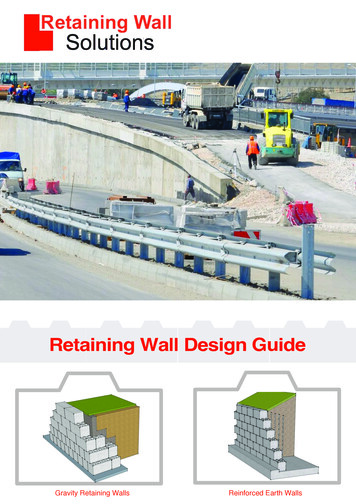
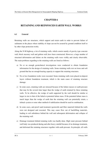
Foundation EngineeringChapter 8: Design and Analysis of Retaining Walls8.3.2 Tentative Dimensions of Common Types of Retaining WallsRetaining wall design proceeds with the selection of tentative dimensions, see Fig.(8.3)which are then analyzed for stability and structural requirements and revised as required. Sincethis is a trial process, several solutions of the problem may be obtained, all of which aresatisfactory.8.3.2.1 Gravity Retaining WallsGravity-wall dimensions may be taken as shown in Fig.(8.3-a). Gravity walls, generally,are trapezoidal in shape, but also may be built with broken backs. The base and other dimensionsshould be such that the resultant falls within the middle one-third of the base. The top width ofthe stem should be not less than 30cm. Because of the massive proportions and resulting lowconcrete stresses, low-strength concrete can generally be used for the wall construction.8.3.2.2 Cantilever Retaining WallsDimensions of the retaining wall should be adequate for structural stability and satisfylocal building-code requirements. The tentative dimensions shown in Fig.(8.3-b) are based inpart on the history of satisfactorily constructed walls, and may be used in the absence of otherdata. However, it may result in an overly conservative design. The top width of the stem shouldnot be less than 30cm. While the base of the stem should be thick enough to satisfy the shearrequirements without use of shear reinforcing steel. The base-slab dimensions should be suchthat the resultant of the vertical loads falls within the middle one-third. If the resultant fallsoutside the middle one-third, the toe pressures may be excessively large and only a part of thefooting will be effective.8.3.2.3 Counterfort Retaining WallsTypical proportions for counterfort retaining walls are as shown in Fig.(8.3c). Thesedimensions are only a guide, and thinner walls of (10-15) cm thick sections may be used ifstructural stability is satisfied. The use of a counterfort will be determined by the relative costs offorms; concrete, reinforcing, and labor. The spacing of the counterforts is a trial process to give aminimum cost. The most economical spacing appears to be (1/3-1/2) the height of the wall. Acounterfort may be built into the beginning of the wall or by allowing a part of the wall tooverhang. The overhanging configuration may prove to be more economical since it saves theconcrete and formwork on the two counterforts at the joint. The counterfort wall may beconstructed without a toe if additional front clearance is needed and the sliding and overturningstability requirements are met.Foundation EngineeringDesign and Analysis of Retaining WallsDr.Farouk Majeed Muhauwiss.4
Foundation EngineeringChapter 8: Design and Analysis of Retaining Walls(a) GRAVITY WALL(b) CANTILEVER WALL(c) COUNTERFORT RETAINING WALLFig.(8.3): Tentative dimensions of common types of retaining walls.5
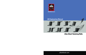
Foundation EngineeringChapter 8: Design and Analysis of Retaining Walls8.4 FORCES ACTING ON RETAINING WALLSThe design of a retaining wall must account for all applied loads. The loads that are ofprimary concern are the lateral earth pressures induced by the retained soil. Under normalconditions, the lateral earth pressure is at rest condition. But, if the wall deflects slightly, stresseswere exerted in the soil, these are; a passive earth pressure ( PP ) in front of the wall, and an activeearth pressure ( Pa ) behind the wall. For design purposes, the passive earth pressure in front ofthe wall, is neglected to avoid any problem resulting from removing the soil in front of the wall.The active and passive pressures are assumed to increase linearly with depth as a functionof the weight of soil. The magnitude and direction of these pressures as well as their distributiondepend upon many variables; such as height of the wall, the slope of the ground surface ( β ), typeof backfill used, draining of the backfill, level of the water table, added loads applied on thebackfill (surcharges either live or dead loads), degree of soil compaction, and movement of thewall caused by the action of the backfill. The forces acting on a retaining wall with level orinclined backfill are shown Fig.(8.4).The active and passive earth pressures are computed as:1Pa .γH′ 2 .K a . . . .(8.1)21Pp .γH 2p .K p . . . . .(8.2)2where, the coefficients of active and passive lateral earth pressures are computed as:For a level backfill:Ka 1 sin φor K a tan 2 (45 φ / 2) . . . . .(8.3)1 sin φFor an inclined backfill:K a cos βcos β cos 2 β cos 2 φcos β cos 2 β cos 2 φ . . . .(8.4)NOTE: A surcharge load has a same effect as an additional (equivalent) height of earth ( H su )above the ground surface obtained as: H su Wsu / γ backfill where Wsu is thesurcharge load per square unit and γ backfill is the unit weight of backfill soil. Thisadditional height due to surcharge, adds a rectangle of pressure behind the wall with atotal lateral force assumed acting at its mid-height6
Foundation EngineeringChapter 8: Design and Analysis of Retaining WallsSurchargeqsG.S.This soil maybe removed w s 2w c 2w c1 w s1This soil maybe removed w s 2w c 21Pa γH 2 K a21PP γH 2p K PH/32w c31PP γH 2pKP2Bq Toew c3q Toe V ws wcH/2H/3eq heelPs K a qs.H1Pa γH 2 K a2BFR c a .B′ V tan δew c1 w s1 FR c a .B′ V tan δ PPFR c a .B′ V tan δq heel V ws wc FR c a .B′ V tan δ PP(a) level backfill without surcharge.(b) level backfill with surchargew s2w s2G.S.SurchargeqsββaThis soil maybe removed w w c2s3PP w c1 w s1Pshw c1 w s11Pa γH ′ 2 K a This soil may2be removed ws3 w c2H′12Pav Pa γH′ K a2βH ′ /3PP Be1 2γH p K P2q Toe V w s w c Pvwhere: Pah Pa cos β ,H ′ /3PahBeq heelH ′ /2w c3FR c a .B′ V. tan δq ToePs K a qs.H ′cw c31 2γH p K P2PsvFR c a .B′ V. tan δq heel V w s w c PvPav Pa sin β ,ws ws1 ws 2 ws 3 , wc wc1 wc 2 wc 3(c) Sloped backfill without surcharge.H ′ H ac. tan β , FR c a .B′ V tan δ PP(d) Sloped backfill with surchargeFig.(8.4): Forces acting on a retaining wall.7
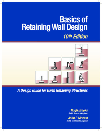
Foundation EngineeringChapter 8: Design and Analysis of Retaining Walls8.5 STABILITY CONSIDERATIONSAt the beginning, tentative dimensions can be used and then analyzed for both external andinternal (structural design requirements), for these purposes, computer programs for design andanalysis of retaining walls may be helpful.8.5.1 EXTERNAL STABILITYThis stability includes five checksas shown below and explained with reference toFig.(8.5).(1) Check for Overturning about Toe (point O),(2) Check for Sliding along the Base of the Wall,(3) Check for Bearing Capacity Failure of the Base Soil,(4) Check for Settlement, and(5) Check Rotational or Deep Shear Failure.w s2Surchargeqsk aw c1ws3This soil maybe removedmDfPP 1 2γH p K P2nbβc Psvw s1Pavw c2LPs K a qs.H′PshH ′ /2w c3j i hBOPa 1γH′2K a2PahH ′ /3dEFR c a .B′ V. tan δGRq Toeeq heel V w s w c Pvwhere, Pah Pa cos β ,Pav Pa sin β ,H ′ H ac. tan β ,ws ws1 ws 2 ws 3 , wc wc1 wc 2 wc 3 FR c a B′ V tan δ PPFig.(8.5): Forces acting on a retaining wall (Sloped backfill with surcharge).8
Foundation Engineering(1)Chapter 8: Design and Analysis of Retaining WallsCheck for Overturning about Toe (point O):SFoverturning Re sisting.Moments MR Overturning.Moments M o 1.5 for cohesionless soilsor . .(8.5) 2.0 for cohesive soils.To determine the resisting forces and moments, the following table should be prepared:WeightArm from 2ws3wc1wc2wc3Ps sin βPavPa sin βPartSoil:Concrete:(1)(2)(3)(1)(2)(3) V MR Overturning moment: M o Pah .( H ′ / 3) Psh .( H ′ / 2)(2)Check for Sliding along the Base of the Wall:In sliding stability analyses, it is common practice to omit the soil in front of the wall.SFSliding Re sisting.Forces FR . . . . . . .(8.6) Sliding.ForceFS 1.5 for cohesionless soils or 2.0 for cohesive soilswhere, the sliding force ( FS ) ( Pa Ps ) or ( Pah Psh )1γH 2 K a .for level ground surface,21Pah γH ′ 2 K a cos β .for inclined ground surface,2Resisting force FR C a .B ′ V. tan δPa V all the vertical forces, including the vertical component of Pa ,B ′ B 2e B the effective length of the base slab,eB B x,2Foundation EngineeringDesign and Analysis of Retaining WallsDr. Farouk Majeed Muhauwiss.9
Foundation EngineeringChapter 8: Design and Analysis of Retaining WallsLocation of resultant of V from Toe ( x ) Net.Moment M R M o V V3322C a c.to. c and δ φ.to. φ3434NOTE: If SFSliding is unsafe: Increase the base dimension B, or Use a key beneath the basenear the stem or at the heel, as shown in Fig.(8.21) until SFSliding 1.5 2.0(a) key near the stem.(b) Key at the heel (more effective).Fig.(8.21): Effect of shear key on retaining wall stability.(3) Check for Bearing Capacity Failure of the Base Soil:SFBearing.Capacity Net.ultimate.bearing.capacity q ult. (net ) . . . . . .(8.7)Max.bearing.pressureq actual 2.5-3.0Calculate the eccentricity by:eB B M R M oB x 22 V V (all the vertical f
however, they have thin vertical concrete slabs behind the wall known as counterforts that tie the wall and base slab together and reduce the shear and bending moment. They are . Foundation Engineering Chapter 8: Design and Analysis of Retaining Walls 2 economical when the wall height exceeds 8m. Whereas, if bracing is in front of the wall and is in compression instead of tension, the wall is .