Transcription
UserManualNon-Programmable ThermostatsTP-N-511Single Stage Heat / CoolConventional and Heat Pumpto 2 Heat / 1 CoolTP-N-521 UpConventional and Heat PumpModel number is located onback of thermostat1 Specifications4 Operating Your Thermostat2 Installation5 Additional Operation Features3 Setting User Options6 Thermostat MaintenanceWarning Turn off power to the heating or coolingequipment before installation.Attention For installation by experienced servicetechnicians only.Read all instructions before proceeding.This thermostat requires 24 Volt AC Power or two (2) properly installed“AA” Alkaline batteries for proper operation. When connecting 24 VoltAC Power the batteries may be installed as a backup. Thermostatinstallation and all components of the system shall conform toClass II Circuits per NEC code.For use only as described in this manual. Any other use will void warranty.1 SpecificationsThis thermostat is compatible with: Single stage heat / cool conventional and heat pump systemsConventional systems up to 2 heat / 1 cool (TP-N-521)Single compressor heat pump systems with an auxiliary heat stage (TP-N-521)250 – 750 millivolt heat only systemsElectrical and control specifications: Electrical Rating: 24 Volt AC 1 amp maximum load per terminal AC Power: 18 – 30 Volts AC DC Power: 3.0 Volt DC (2 “AA” Alkaline Batteries Included) Control Range: 45 – 90 F (7 – 32 C) Temperature Accuracy: /- 1 F ( /- .5 C)Terminations TP-N-511 – Rc, Rh, O, B, Y1, W1, G, C TP-N-521 – Rc, Rh, O, B, Y1, E/W1, G, W2, CTPN-100-01
2 InstallationWarningDisconnect power before beginning installation.Thermostat LocationInstall the thermostat approximately 5 feet (1.5m) above the floor in anarea that has a good amount of air circulation and maintains an averageroom temperature.Avoid installation in locations where the thermostat can be affected bydrafts, dead air spots, hot or cold air ducts, sunlight, appliances, concealedpipes, chimneys and outside walls.Install your new TRADEPRO thermostat in 5 basic steps:12345Install the Sub-BaseProvide PowerConnect Your WiresSet Installer SwitchesAttach Thermostat to Sub-Base1Install the Sub-Base: Remove the sub-base from the body of the thermostat. Mount the sub-base as shown below:UPUPDrill 3/16” pilot holes inyour desired location.Use supplied anchors fordrywall or plaster.1
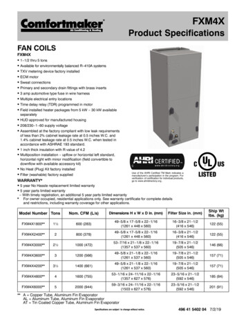
2 Provide Power For 24 Volt AC power, you must connect the common side of the transformer to the C terminal on the thermostat sub-base. For primary or back-up power, insert the 2 supplied “AA” type alkalinebatteries into the battery compartment located in the rear housing of thethermostat. Make sure to position the Positive ( ) and Negative (-) sidesof the batteries correctly with the /- symbols in the battery compartment.3 Connect Your WiresConventional SystemsTypical Wiring ConfigurationsNOTE: The “Installer Switch” option will be configured in the next step.Heat Only or MillivoltSet Installer Switch to CONVRhWGCPower ConnectionHeat Relay (appears as W1/E on TP-N-521)Fan Relay [note 4]24 Volt AC Transformer Common [note 1]1 HEAT / 1 COOL Single or Dual TransformerSet Installer Switch to CONVRhRcW1Y1GC24 Volt AC Power (heating transformer) [note 2]24 Volt AC Power (cooling transformer) [note 2]Heat Relay (appears as W1/E on TP-N-521)Compressor RelayFan Relay24 Volt AC Transformer Common [note 1, 3]2 HEAT / 1 COOL Single or Dual Transformer (TP-N-521 Only)Set System Type to CONVRhRcW1W2Y1GC24 Volt AC Power (heating transformer) [note 2]24 Volt AC Power (cooling transformer) [note 2]Heat Relay Stage 1Heat Relay Stage 2Compressor Relay Stage 1Fan Relay24 Volt AC Transformer Common [note 1, 3]NOTES - Conventional Systems[1] If batteries are installed the 24 Volt AC common connection is optional[2] Remove factory installed jumper for dual transformer systems[3] In dual transformer systems, transformer common must come fromcooling transformer[4] If needed for systemProvide disconnect and overload protection as required.2
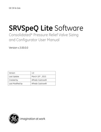
Heat Pump SystemsTypical Wiring ConfigurationsNOTE: The “Installer Switch” option will be configured in the next step.1 HEAT / 1 COOL - No Auxiliary HeatSet Installer Switch to HPRhRcO or BY1GC24 Volt AC PowerConnected to Rh with supplied Jumper WireChangeover Valve [note 2]Compressor RelayFan Relay24 Volt AC Transformer Common [note 1]2 HEAT / 1 COOL - Including Auxiliary Heat (TP-N-521 only)Set Installer Switch to HPRh24 Volt AC PowerRcConnected to Rh with supplied Jumper WireO or B Changeover Valve [note 2]Y1Compressor Relay (1st stage heating/cooling)W2Auxiliary Heat Relay (2nd stage heating) [note 3]W1/EEmergency Heat Relay [note 3]GFan RelayC24 Volt AC Transformer Common [note1]NOTES - Heat Pump Systems[1] If batteries are installed the 24 Volt AC common connection is optional.[2] Select O for cool active or B for heat active.[3] Install a field supplied jumper between the W2 and E terminals ifthere is no separate emergency heat relay installed.Provide disconnect and overload protection as required.4Set Installer SwitchesSwitchFactory SettingDefault Options CommentsCONV / HPCONVCONVHPSelect for conventional systemsSelect for heat pump systemsF/CFFCSelect for fahrenheit temperature scaleSelect for celsius temperature scaleHE / HGHGHGHESelect for gas heatSelect for electric heatNOTE: The reset button should be pressed after making any changes to theinstaller switches.3
5Attach Thermostat to Sub-Base1. Line up the thermostat body with the sub-base.2. Carefully push the thermostat body against the sub-base until it snapsinto place.3. Insert quick reference card into slot on top of thermostat.3 Setting User OptionsAdvanced User OptionsUser options allow you to customize some of your thermostats features.Most users will not need to make any changes to the settings in this section.To access the User Options menu, hold down both the and buttonsfor approximately 3 seconds until the screen changes and displaysthe first User Option.Press the or button to change the setting for the displayed User Option.After you have made your desired setting, press and together toadvance to the next User Option.The thermostat will return to normal mode after your last user option ismade or after no keys have been pressed for 15 seconds.Table of User 1st stage0.50.5, 1.0differentialor 2.022.02nd stagedifferential(TP-N-521)1.0, 2.0,3.0, 4.0,5.0 or 6.0CommentsSelect a 1st stage temperaturedifferential of .5 , 1 or 2 F (.2 , .5 or 1 C)Select a 2nd stage temperaturedifferential of 1 , 2 , 3 , 4 , 5 or 6 F(.5 , 1 , 1.5 , 2 , 2.5 or 3 C)Detailed Explanation of User Options:Temperature Differential(User Option 1 and 2)The differential setting is the temperature control range that your thermostatwill provide. The smaller the setting, the tighter your range of temperaturecontrol and comfort will be. The 2nd stage differential is only for systemswith a second stage of heating (auxiliary heat).4
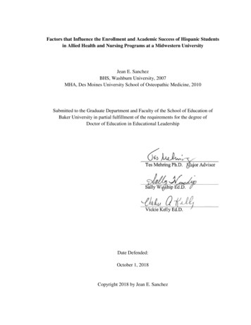
4 Operating Your ThermostatSetting the System Control ModeThe System Control has several modes of operation that can be selected bymoving the SYSTEM switch to the appropriate position.COOL Only your cooling system will operateOFFHeating and cooling systems are off.HEAT Only your heating system will operate.Additional Switch Position (Model TP-N-521 Only):EMER Operates a backup heat source (Emergency Heat) for heat pumpsystems only.NOTE: If your model TP-N-521 was configuredfor a conventional system (CONV) then you will nothave the EMER (emergency heat) option and “NOEMER SET” will flash in the display if EMER isselected with the system switch.Setting the Fan Control ModeThe Fan Control has 2 modes of operation – AUTOand ON. The mode can be selected by moving theFAN switch to the appropriate position.AUTOThe system fan will run only when yourheating or cooling system is running.ONThe system fan stays on.Temperature AdjustmentPress theorbutton to adjust the current set point temperature.Status IndicatorsStatus indicators appear in the display to letyou know if your system is heating, coolingor off.HEAT ON Indicates your heating system is running.COOL ON Indicates your cooling system is running.Additional Status Indicators (Model TP-N-521 Only):AUXIndicates that the auxiliary stage of heating is running(Multi-Stage Systems only).EMERIndicates that the emergency heating system is running(Heat Pump Systems only).5
Resetting the ThermostatThis thermostat provides you with a reset button that will erase all of youruser settings. To reset the thermostat, use a small object such as a toothpick or paperclip and gently press the button located inside the small holeon the front of the thermostat housing labeled “reset”.5 Additional Operation FeaturesCompressor ProtectionThis thermostat includes an automatic compressor protection delay toavoid potential damage to your system from short cycling. This featureactivates a short delay after turning off the system compressor.6 Thermostat MaintenanceChanging the BatteriesDepending on your particular installation, this thermostatmay be equipped with two (2) “AA” type alkaline batteries.If batteries are installed and they become low, a low battery indicator willappear in the display. You should change your batteries immediately whenyou see the low battery signal by following these instructions.1.2.3.4.Remove thermostat body by gently pulling it from base.Remove old batteries and replace with new batteries.Make sure to correctly position the ( ) and (-) symbols.Gently push thermostat body back onto base.NOTE: We recommend replacing the thermostat batteries annually or if thethermostat will be unattended for an extended period of time.Thermostat CleaningNever spray any liquid directly on the thermostat. Using a soft damp clothwipe the outer body of the thermostat. Never use any abrasive cleansers toclean your thermostat.Store this manual for future reference.3 Year Limited WarrantyTRADEPRO warrants each new TRADEPRO thermostat against any defects that aredue to faulty material or workmanship. This warranty and our liability does not apply tobatteries, nor does it include damage to merchandise or the thermostat resulting fromaccident, alteration, neglect, misuse, improper installation or any other failure to followTRADEPRO installation and operating instructions. This limited warranty applies forthe duration of the warranty period from the original date of purchase by a professionalservice technician.TRADEPRO agrees to repair or replace at its option any TRADEPRO thermostat underwarranty provided it is returned postage prepaid to our warranty facility in a paddedcarton within the warranty period, with proof of the original date of purchase and abrief description of the malfunction. This limited warranty does not include the cost ofremoval or re-installation.This warranty gives you specific legal rights and you may also have other rights thatvary from state to state or province to province. Answers to any questions regarding ourlimited warranty may be obtained by writing our corporate offices.For warranty service, please visit your nearest TRADEPRO facility.Technical Assistance: 866-268-5599 (U.S.) 630-844-1968 (Outside the U.S.) 2018 TRADEPRO All Rights Reserved Made in China.TPN-100-01
To reset the thermostat, use a small object such as a tooth pick or paperclip and gently press the button located inside the small hole on the front of the thermostat housing labeled “reset”. 5 Additional Operation Features Compressor Protection This thermostat includes an automatic compressor protection delay to avoid potential damage to your system from short cycling. This feature .