Transcription
Compressed Air System Design4ChapterCompressed Air & Gas Handbook n Seventh EditionJanuary 2021
Chapter4Compressed Air System DesignEfficient Compressed Air SystemsWhen a compressed air system is properly designed, installed, operated and maintained, it is a major source of efficient industrial power, possessing many inherentadvantages. Compressed air is safe, economical, adaptable, easily transmitted, andprovides labor saving power. Compressed air is often referred to as being the fourthutility within industry, behind electricity, water, and natural gas. The cost of a complete compressed air system and pneumatic tools is relatively small in comparisonwith the utility provided by their use.Goal of an Efficient Compressed Air SystemThe primary goal of a compressed air system is to deliver a reliable supply of clean,dry, compressed air at a stable pressure to every end user within the compressed airsystem, at the lowest cost possible. Many factors must be considered when designinga compressed air system to ensure its efficiency, reliability, and safety.This chapter will focus on the roles that the following system parameters play inachieving the ultimate goal of a well-designed compressed air system:nnnnnnAir flowAir pressureAir qualityType and number of compressorsAir distribution and system layoutSystem efficiencyAir Flow RequirementsDetermining the proper compressor capacity (supply) to install in order to satisfy thesystem compressed air usage (demand) is a vital and basic fundamental that is oftenmisunderstood. It is very important to understand that the flow requirements of allpneumatic equipment are stated in free-air volumes: the amount of atmosphericair, compressed to a desired pressure, required to operate the tool as designed. Aircompressor capacity rating is also stated in free-air volume. Determining the totaldemand of a compressed air system can be a complicated and oftentimes confusingtask, especially in large systems with many end users. There are typically two methodsfor determining the total demand of a compressed air system; calculating or measuring. Both methods will be discussed below. 2021 CAGI1
Calculating Air Flow RequirementsUnderstanding your constituents of demand is the first step to properly sizing yoursystem. Whether you are increasing the demand of a current facility or beginning witha new system, calculating the demand of your compressed air system can be difficultdue to the fluctuating demand of each air-consuming application. Nonetheless, understanding demand begins with summing the average air consumption of each user.A study of pneumatic tools and devices in a typical manufacturing plant will showthat some of these tools and devices operate almost constantly and others operateinfrequently, yet may require a relatively large volume of air while in use. It also willbe found that the amount of air actually used by the individual tools and devices willvary considerably in different applications. Accordingly, the demand requirement of acompressed air system should not be calculated as the total of the individual maximum consumptions of all pneumatic devices. This would greatly overstate the systemdemand and result in grossly oversizing the compressor supply. Instead, the demandrequirement of a compressed air system should be calculated as the sum of the average air consumption of each device.Determining the average air consumption of any pneumatic tool or device requiresthe use of the concept known within the industry as load factor. The cfm consumptionfor most pneumatic tools and devices is based on air pressure set at 90 psig whilethe tool/device is running and the tool is operating at 100% of its rated speed; revolutions per minute (rpm) or beats per minute (bpm) for percussive tools. Pneumaticpower tools generally are operated only intermittently and often are operated at lessthan full rated power (speed). The ratio of actual air consumption over a given periodof time to the maximum, continuous full-rated-power air consumption, each measured in cubic feet per minute of free air, is known as the load factor of the device.Load factor x full-power-rated cfm average cfm for the device.Two parameters affect the load factor. The first is the time factor, which is the percentage of time that the device is actually operated over the course of a work shift.The second is the work factor. Maximum work is done when the tool is operatedunder a load at its maximum rated speed; full load condition. Depending upon howmuch work the device is performing, air consumption could be anywhere betweenthe following two conditions; 100% at full load or 0% at stalled load. Work factor isthe actual percentage of full load consumption that is required to perform the actualrequired work. For example, the air consumption of a grinder with full open throttlevaries considerably, depending on how hard the operator applies the grinding wheelagainst the work piece. The more force that is applied to the work piece, the greaterthe work, the slower the speed of the tool, and the lower the cfm consumption. Thework factor therefore is the ratio (expressed as a percentage) of the air consumptionunder actual conditions of operation, to the air consumption when the tool is fullyloaded, and operating at its full-rated power/speed.The load factor is the product of the time factor and the work factor. Multiplying thecfm rating of the tool or device by its load factor results in the average cfm demandof the tool or device. In one plant, the air actually consumed by 434 portable pneumatic tools on production work was only 15% of the summed, maximum ratedcapacities of all tools. To assure maximum accuracy when calculating system demand,it is essential that the most accurate determination or estimate of load factor be usedin calculating the average consumption of each air-using device in the facility. Aver-2
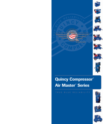
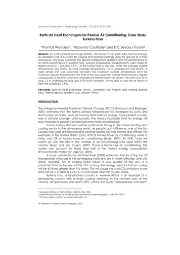
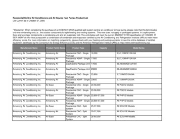
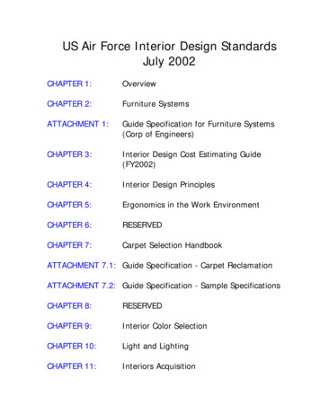
age air consumption calculations should be based upon the maximum continuousfull-rated-power air consumption as stated by the manufacturer. Average air calculations should not be based upon the maximum free-speed consumption of the device,as this condition greatly increases the cfm consumption of the device.Chapter4When designing an entirely new compressed air system, it is highly desirable toutilize experience with a similar plant. The established load factor can be used as thebasis of a good estimate for the new system. Care should be taken when calculatingload factor to assure accuracy. Guesses and rules-of-thumb should be avoided. Thesemethods can cause gross error in determining the proper amount of supply to install.For instance, one rule-of-thumb states that the compressor capacity should be aboutone third of the 100% load factor requirement of all the pneumatic tools. This ruleof-thumb leaves too much to chance.Table 4.1, shows the air requirements at 100% load factor of various tools and thisinformation can be used for preliminary system demand estimates. These figures areapproximate and individual tools from different manufacturers may vary by morethan 10% from the figures given. Contact the manufacturer of the air device for themost accurate consumption information. Table 4.2 shows the cubic feet per minute ofair required for various sizes of sandblast nozzles.Many pieces of production equipment are actuated by pneumatic cylinders. Theseinclude automatic feed devices, chucks, vises, clamps, presses, intermittent reciprocating and rotary motion devices, door openers and many other devices. Such devicesusually have low air consumption and are themselves inexpensive. Accordingly, theirusage in automated production processes is significant and increasing. Air consumption for such cylinders is shown in Table 4.3. This table shows the theoretical volumeswept out by the piston during one full stroke. For demand calculation purposes, thisvolume at pressure must be converted into a flow rate of free air. Many cylinders contain air cushioning chambers which increase the volume somewhat over the tabledfigures. In actual use, the air pressure to the cylinder might be regulated to a pressureconsiderably lower than the system line pressure. In such a case, the regulated articlepressure should be used rather than full line pressure in converting the tabled figuresto free air conditions. Similarly, if a limit switch cuts off the air supply when a certainforce is exerted by the cylinder, the corresponding pressure should be calculated andused rather than full line pressure in converting the tabled figures to free air conditions. In many applications, the full available piston stroke is not needed. In fact, areduced length of stroke may be an advantage in reducing operating time. The airconsumption for such cases is calculated using only the actual stroke.Table 4.4 demonstrates how to calculate the average demand of a compressed airsystem by applying the appropriate load factors to the various air consuming devicesin an industrial facility. Once you have determined the average demand of the systemby calculating and summing the average demands of all air-using applications, youhave a baseline of average demand with which to work. While it is usually safe touse an accurately calculated average system consumption for determining the required amount of compressors to be installed, it is important to realize that becausemany applications are intermittent in nature, the possibility exists for all users toconsume at the same time, which would be a momentary demand significantly greater than the average consumption. This maximum demand can be addressed withcompressor horsepower or, more efficiently, with the proper amount of storage withinthe system. The greater the total system storage, the closer to the average calculateddemand you can size the supply equipment. 2021 CAGI3
Table 4.1 Air Requirements of Various ToolsToolFree Air, cfm at 90 psig, 100% Load FactorGrinders, 6" and 8" wheelsGrinders, 2" and 2 1/2" wheelsFile and burr machinesRotary sanders, 9" padsRotary sanders, 7" padsSand rammers and tampers,1" x 4" cylinder1 1/4" x 5"” cylinder1 1/2" x 6" cylinderChipping hammers, weighing 10-13 lbHeavyWeighing 2-4 lbNut setters to 5/16" weighing 8 lbNut setters 1/2"” to 3/4" weighing 18 lbSump pumps, 145 gal (a 50-ft head)Paint spray, averageVaries fromBushing tools (monument)Carving tools (monument)Plug drillsRiveters, 3/32"-1" rivetsLarger weighing 18-22 lbRivet bustersWood borers to 1" diameter weighing 4 lb2" diameter weighing 26 lbSteel drills, rotary motorsCapacity up to 1/4" weighing 1 ¼-4 lbCapacity 1/4" to 3/8” weighing 6-8 lbCapacity 1/2” to 3/4" weighing 9-14 lbCapacity 7/8" to 1” weighing 25 lbCapacity 1 1/4" weighing 30 lbSteel drills, piston typeCapacity 1/2" to 3/4" weighing 13-15 lbCapacity 7/8" to 1 1/4" weighing 25-30 lbCapacity 1 1/4" to 2" weighing 40-50 lbCapacity 2" to 3" weighing 55-75 -110Table 4.2 Cubic Feet of Air per Minute Required by SandblastNozzle 73867105151268Compressed Air Gage Pressure 06.5152658103161232412
Table 4.3 Volume of Compressed Air in Cubic Feet Required per Stroke toOperate Air CylinderPiston Diameter Length of Stroke in Inches*in Inches123456781 1/41 7/822 1/82 1/42 3/82 1/22 5/82 3/42 7/833 1/83 1/43 3/83 1/23 5/83 3/43 7/844 1/84 1/44 3/84 1/24 5/84 3/44 7/855 1/85 1/45 3/85 1/25 5/85 3/45 7/860.00139 0.00278.00158 .00316.00182 .00364.00205 .0041.0023.0046.00256 .00512.00284 .00568.00313 .00626.00343 .00686.00376 .00752.00409 .00818.00443 .00886.0048.0096.00518 .01036.00555 .0112.00595 .0119.0064.0128.0068.01362.00725 .0145.00773 25 .0205.0108.0216.0114.0228.01193 .0239.0125.0251.0131.0263.01375 0412.0432.045.047.049290.00555 0.00694 0.00832 0.00972 0.0111 0.0125.00632 .0079.00948 .01105 .01262 .0142.00727 .0091.0109.0127.0145 .01636.0082.0103.0123.0144.0164 .0185.0092.0115.0138.0161.0184 .0207.01025 .0128.01535 .01792 .02044 .0230.01137 .0142.0171.0199.0228 .0256.01254 .01568 .0188.0219.0251 .0282.0137.0171.0206.0240.0272 .0308.01503 .01877 .0226.0263.0301 .0338.0164.0204.0246.0286.0327 .0368.0177.0222.0266.0310.0354 .0399.0192.024.0288.0336.0384 .0432.0207.0259.031.0362.0415 .0465.0222.0278.0333.0389.0445 .050.0238.0298.0357.0416.0477 .0536.0256.032.0384.0447.0512 .0575.0273.0341.041.0477.0545 541.0618 .0695.0328.041.0492.0574.0655 .0738.0348.0435.0522.0608.0694 .0782.0368.046.0552.0643.0735 .0828.0388.0485.0582.0679.0775 .0873.041.0512.0615.0717.0818 .0922.0431.054.0647.0755.0862 837.0955 .094.110.1254 6.1435.151.158.165.173.180.188.1974* These volumes are for single-acting cylinders. For double-acting cylinders, multiply by 2 and subtract the volume of the piston rod. Thesevolumes are the theoretical volume displaced by the piston during one full stroke. This volume must be converted to a flow
Understanding your constituents of demand is the first step to properly sizing your system. Whether you are increasing the demand of a current facility or beginning with a new system, calculating the demand of your compressed air system can be difficult due to the fluctuating demand of each air-consuming application. Nonetheless, un-File Size: 578KBPage Count: 33