Transcription
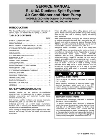
SERVICE MANUALR 410A Ductless Split SystemAir Conditioner and Heat PumpMODELS: DLC4(A/H) Outdoor, DLF4(A/H) IndoorSIZES: 9K, 12K, 18K, 24K, 30K, and 36KINTRODUCTIONThis Service Manual provides the necessary information toservice, repair, and maintain the DLF4(A,H), DLC4(A/H)TABLE OF CONTENTSPAGESAFETY CONSIDERATIONS . . . . . . . . . . . . . . . . . . . . . . . . 1SPECIFICATIONS . . . . . . . . . . . . . . . . . . . . . . . . . . . . . . . . . . 2MODEL / SERIAL NUMBER NOMENCLATURE . . . . . . . 16STANDARD FEATURES AND ACCESSORIES . . . . . . . . 17DIMENSIONS . . . . . . . . . . . . . . . . . . . . . . . . . . . . . . . . . . . . . 18CLEARANCES . . . . . . . . . . . . . . . . . . . . . . . . . . . . . . . . . . . . 22SYSTEM OPERATING ENVELOPE . . . . . . . . . . . . . . . . . . 23ELECTRICAL DATA . . . . . . . . . . . . . . . . . . . . . . . . . . . . . . . 25CONNECTION DIAGRAMS . . . . . . . . . . . . . . . . . . . . . . . . . 26WIRING DIAGRAMS . . . . . . . . . . . . . . . . . . . . . . . . . . . . . . . 27REFRIGERATION SYSTEM DIAGRAM . . . . . . . . . . . . . . . 36REFRIGERANT LINES . . . . . . . . . . . . . . . . . . . . . . . . . . . . . 38SYSTEM EVACUATION AND CHARGING . . . . . . . . . . . . 39CONTROL SYSTEM . . . . . . . . . . . . . . . . . . . . . . . . . . . . . . . 40MODES OF OPERATION . . . . . . . . . . . . . . . . . . . . . . . . . . . 44TROUBLESHOOTING . . . . . . . . . . . . . . . . . . . . . . . . . . . . . 47DIAGNOSTIC CHARTS . . . . . . . . . . . . . . . . . . . . . . . . . . . . 48MALFUNCTION ANALYSIS . . . . . . . . . . . . . . . . . . . . . . . . . 55APPENDIX . . . . . . . . . . . . . . . . . . . . . . . . . . . . . . . . . . . . . . . 79SAFETY CONSIDERATIONSInstalling, starting up, and servicing air conditioningequipment can be hazardous due to system pressures,electrical components, and equipment location (roofs,elevated structures, etc.).Only trained, qualified installers and service mechanicsshould install, start up, and service this equipment.Untrained personnel can perform basic maintenancefunctions such as cleaning coils. All other operations shouldbe performed by trained service personnel.When working on the equipment, observe precautions in theliterature and on tags, stickers, and labels attached to theequipment.Follow all safety codes. Wear safety glasses and workgloves. Keep quenching cloth and fire extinguisher nearbywhen brazing. Use care in handling, rigging, and settingbulky equipment.Read these instructions thoroughly and follow all warningsor cautions included in literature and attached to the unit.Consult local building codes and National Electrical Code(NEC) for special requirements. In Canada, refer to currenteditions of the Canadian Electrical Code, CSA 22.1.Recognize safety information. This is the safety alertsymbol !! . When you see this symbol on the unit and ininstructions or manuals, be alert to the potential for ARNING, and CAUTION. These words are used with thesafety alert symbol. DANGER identifies the most serioushazards which will result in severe personal injury or death.WARNING signifies hazards which could result in personalinjury or death. CAUTION is used to identify unsafepractices which may result in minor personal injury orproduct and property damage. NOTE is used to highlightsuggestions which will result in enhanced installation,reliability, or operation.WARNING!ELECTRICAL SHOCK HAZARDFailure to follow this warning could result in personalinjury or death.Before installing, modifying, or servicing system, mainelectrical disconnect switch must be in the OFFposition. There may be more than 1 disconnect switch.Lock out and tag switch with a suitable warning label.!CAUTIONEQUIPMENT DAMAGE HAZARDFailure to follow this caution may result in equipmentdamage or improper operation.Do not bury more than 36 in. (914 mm) of refrigerantpipe in the ground. If any section of pipe is buried, theremust be a 6 in. (152 mm) vertical rise to the valveconnections on the outdoor units. If more than therecommended length is buried, refrigerant may migrateto the cooler buried section during extended periods ofsystem shutdown. This causes refrigerant slugging andcould possibly damage the compressor at start up.421 01 9204 00 1/03/13
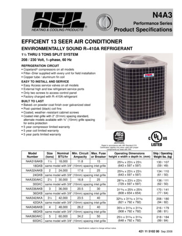
SERVICE MANUALR 410A Ductless Split System: DLF4(A/H), DLC4(A/H)PRODUCT SPECIFICATIONSModel Indoor UnitFunctionRated VoltageFrequency(Inverter differentCompressor speed)Total Capacity(Inverter differentCompressor speed)Power Input(Inverter differentCompressor speed)Rated InputRated 41153100 / 106002650 / 90001300 / eating115V7063414415153100 / 106003250 / 111002650 / 90002820 / 95001300 / 4435930 / .00.38Cross Flow Fanf3.6x25.4Aluminum Fin Copper Tubef0.32 0.060.814.222 / 38Cross Flow Fanf3.6x25.4Aluminum Fin Copper Tubef0.32 0.06Inch25.4 x 10.5 x 125.4 x 10.5 x 1WAdB (A)dB (A)dB (A)dB (A)dB (A)dB (A)InchInchInchMP24AA2.43.1534302644403633 x 11 x 736 x 14 x 1029 / 38MP24AA2.43.1534302644403633 x 11 x 736 x 14 x 1029 / 38HzHzHzW/BtuhW/BtuhW/BtuhWWWWWAACFMAir VolumeDehumidifying VolumeEER / C.O.PSEER / HSPFIndoor UnitI/hSpeedFan MotorFanEvaporatorSwing MotorSHHMLOutputCapacitorRLATypeDiameter LengthPipe DiameterRow Fin GapCoil length (I) x height(H) x coil width (L)ModelOutputFuseSound Pressure LevelSound Pressure LevelDimension (WxHxD)Dimension of Package (WxHxD)Net Weight / Gross Weight2HMLHMLr/minr/minr/minr/minWmFAInch421 01 9204 00
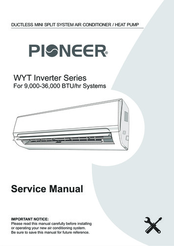
SERVICE MANUALR 410A Ductless Split System: DLF4(A/H), DLC4(A/H)PRODUCT SPECIFICATIONS (Cont.)Model Outdoor er InputOverload ProtectorrAAWThrottling MethodStarting MethodWorking Temperature Range FCoilHeat Exchanger CoilPipe DiameterRows Fin GapCoil Length (I) x Height (H) x Width (L)SpeedOutput of Fan MotorFan MotorR.L.A.CapacitorAir Flow Volume of Outdoor UnitTypeFanDiameterDefrosting MethodClimate TypeIsolationMoisture ProtectionPermissible Excessive Operating Pressure forthe Discharge SidePermissible Excessive Operating Pressure forthe Suction SideSound Pressure LevelSound Power LevelDimensions (WxHxD)Dimensions of Package (WxHxD)Net Weight / Gross WeightName of RefrigerantRefrigerantWeightLength (m)Gas AdditionalChargeConnection PipeinchinchinchrpmWAmFFt3/minDLF4AV09J1ASanyoC 6RZ110H1ATwin Rotary334.59 / 2.81775 / 735Int11I 3979Electronic Expansion ValveThrottlingDLF4HV09J1ASanyoC 6RZ110H1ATwin Rotary334.59 / 2.81775 / 735Int11I 3979Electronic Expansion Valve ThrottlingTransducer Starting55 115Aluminum Fin CopperTubeAluminum Fin Copper Tubef0.32 0.0631.5 x 19.5 x.05900 / 650400.17/1118Axial Fan15.7/T1IIP24f0.32 0.0631.5 x 19.5 x.05900 / 650900400.17/1118Axial Fan15.7/T1IIP24Mpa3.83.8Mpa1.21.2DB (A)DB (A)inchinchLbs.Oz.Ft. 50 6333 X 21 X 12.634.5 X 22.8 X 14.296 / 110R410A4216 50 6333 X 21 X 12.634.5 X 22.8 X 14.296 / 110R410A4216Oz/ft1.16131.1613inchLiquid Pipe Diameterinchf1/4Gas Pipe Diameterinchf3/8Max. Interunit height DifferenceFt.33Max. Interunit Piping LengthFt.66* The above data is subject to change without notice. Please refer to the nameplate of the unit.421 08 9204 00Transducer Starting55 1155 24f1/4f3/833663
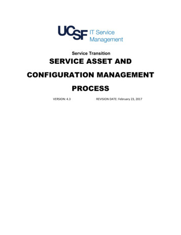
SERVICE MANUALR 410A Ductless Split System: DLF4(A/H), DLC4(A/H)PRODUCT SPECIFICATIONSModel Indoor UnitFunctionRated VoltageFrequency(Inverter differentCompressor speed)Total Capacity(Inverter differentCompressor speed)Power Input(Inverter differentCompressor speed)Rated InputRated 41153100 / 106002650 / 90001300 / eating115V7063414415153100 / 106003250 / 111002650 / 90002820 / 95001300 / 4435930 / .00.38Cross Flow Fanf3.6x25.4Aluminum Fin Copper Tubef0.32 0.060.814.222 / 38Cross Flow Fanf3.6x25.4Aluminum Fin Copper Tubef0.32 0.06Inch25.4 x 10.5 x 125.4 x 10.5 x 1WAdB (A)dB (A)dB (A)dB (A)dB (A)dB (A)InchInchInchMP24AA2.43.1534302644403633 x 11 x 736 x 14 x 1029 / 38MP24AA2.43.1534302644403633 x 11 x 736 x 14 x 1029 / 38HzHzHzW/BtuhW/BtuhW/BtuhWWWWWAACFMAir VolumeDehumidifying VolumeEER / C.O.PSEER / HSPFIndoor UnitI/hSpeedFan MotorFanEvaporatorSwing MotorSHHMLOutputCapacitorRLATypeDiameter LengthPipe DiameterRow Fin GapCoil length (I) x height(H) x coil width (L)ModelOutputFuseSound Pressure LevelSound Pressure LevelDimension (WxHxD)Dimension of Package (WxHxD)Net Weight / Gross Weight4HMLHMLr/minr/minr/minr/minWmFAInch421 08 9204 00
SERVICE MANUALR 410A Ductless Split System: DLF4(A/H), DLC4(A/H)PRODUCT SPECIFICATIONS (Cont.)Model Outdoor er InputOverload ProtectorrAAWThrottling MethodStarting MethodWorking Temperature Range FCoilHeat Exchanger CoilPipe DiameterRows Fin GapCoil Length (I) x Height (H) x Width (L)SpeedOutput of Fan MotorFan MotorR.L.A.CapacitorAir Flow Volume of Outdoor UnitTypeFanDiameterDefrosting MethodClimate TypeIsolationMoisture ProtectionPermissible Excessive Operating Pressure forthe Discharge SidePermissible Excessive Operating Pressure forthe Suction SideSound Pressure LevelSound Power LevelDimensions (WxHxD)Dimensions of Package (WxHxD)Net Weight / Gross WeightName of RefrigerantRefrigerantWeightLength (m)Gas AdditionalChargeConnection PipeinchinchinchrpmWAmFFt3/minDLC4AV12J1ASanyoC 6RZ110H1ATwin Rotary334.59 / 2.81775 / 735Int11I 3979Electronic Expansion ValveThrottlingDLC4HV12J1ASanyoC 6RZ110H1ATwin Rotary334.59 / 2.81775 / 735Int11I 3979Electronic Expansion Valve ThrottlingTransducer Starting55 115Aluminum Fin CopperTubeAluminum Fin Copper Tubef0.42 0.0630.2 x 20 x0.9900 / 680400.17/1118Axial Fan15.7/T1IIP24f0.42 0.0630.2 x 20 x0.9900 / 680900400.17/1118Axial Fan15.7Auto DefrostT1IIP24Mpa3.83.8Mpa1.21.2DB (A)DB (A)inchinchLbs.Oz.Ft. 53 6533 X 21 X 12.634.5 X 22.8 X 14.2107 / 118R410A45.516 53 6533 X 21 X 12.634.5 X 22.8 X 14.2107 / 118R410A45.516Oz/ft1.16131.1613inchLiquid Pipe Diameterinchf1/4Gas Pipe Diameterinchf3/8Max. Interunit height DifferenceFt.33Max. Interunit Piping LengthFt.66* The above data is subject to change without notice. Please refer to the nameplate of the unit.421 08 9204 00Transducer Starting55 1155 75f1/4f3/833665
SERVICE MANUALR 410A Ductless Split System: DLF4(A/H), DLC4(A/H)PRODUCT SPECIFICATIONS (Cont.)ModelRated VoltagePowerRated FrequencySupplyPhasesPower Supply ModeCooling Capacity (Min Max)Heating Capacity (Min. Max)Cooling Power Input (Min. Max.)Heating Power Input (Min. Max.)Cooling Current InputHeating Current InputRated InputRated CurrentAir Flow Volume (S/H/M/L)Dehumidifying VolumeEERCOPSEERHSPFApplication AreaModel Indoor UnitFan TypeFan Diameter Length (DXL)Cooling Speed (S/H/M/L)Heating Speed (S/H/M/L)Fan Motor Power OutputFan Motor RLAFan Motor CapacitorEvaporator FormEvaporator Pipe DiameterEvaporator Row fin GapEvaporator Coil Length (LxDxW)Indoor UnitSwing Motor ModelSwing Motor Power OutputFuse CurrentSound Pressure Level (S/H/M/L)Sound Power Level (S/H/M/L)Dimension (WxHxD)Dimension of Carton Box(WxHxD)Dimension of Package (WxHxD)Net WeightGross Weight6WAdB (A)dB (A)inchDLC4AV12K1A208/230601Outdoor12000 (3100 13000)N/A1000 (365 16 24DLF4AH12K1ACross flowf3.6x25.41330/1100/950/750N/A200.21Aluminum Fin Copper Tubef0.272 33.3X10.8X7DLC4HV12K1A208/230601Outdoor12000 (3100 13000)13000 (2400 14000)1000 (365 1080)1000 (340 1360)4.55.2150015335/277/253/2182.9591210.8209.216 24DLF4HH12K1ACross 0.21Aluminum Fin Copper Tubef0.272 62228.736X10.1X14.62228.7V r/minWAmFWinchinchinch421 08 9204 00
SERVICE MANUALR 410A Ductless Split System: DLF4(A/H), DLC4(A/H)PRODUCT SPECIFICATIONS (Cont.)Model Outdoor Power InputOverload ProtectorThrottling MethodSet Temperature RangeCooling Operation Ambient Temperature RangeHeating Operation Ambient Temperature RangeFormPipe DiameterCondenserRows Fin GapCoil Length (LxDxW)SpeedOutput of Fan MotorFan MotorR.L.A.CapacitorAir Flow Volume of Outdoor UnitTypeFanDiameterDefrosting MethodClimate TypeIsolationMoisture ProtectionPermissible Excessive Operating Pressure for theDischarge SidePermissible Excessive Operating Pressure for theSuction 83.2860INT11L 6578Electronic Expansion Valve60.8 860.4 109.4N/AAluminum Fin copper Tubef0.372 0.0529.4x1.7x22680 / 900300.13N/A941.6Axial MCFV50SRotary13.83.2860INT11L 6578Electronic Expansion Valve60.8 860.4 109.4 5 75.0Aluminum Fin copper Tubef0.372 0.0529.4x1.7x22680 / 900300.13N/A941.6Axial Flow15.748Automatic DefrostingT1IIP24Mpa4.34.3Mpa2.52.5AAW F F FinchinchinchrpmWAmFCFMinchSound Pressure Level (H/M/L)DB (A)52/ / Sound Power Level (H/M/L)DB (A)62/ / Dimensions (WxHxD)inch33.4x23.2x12.6Dimensions of Carton Box (WxHxD)inch34.5x14.2x24.8Dimensions of Package (WxHxD)inch34.7x14.3x25.4Net Weight / Gross WeightLbs.88.2 / 97.02Name of ch25Gas Additional ChargeOz/ft0.53Connection PipeLiquid Pipe Outer Diameterinch1/4Gas Pipe Outer Diameterinch3/8Max. Interunit height DifferenceFt.33Max. Interunit Piping LengthFt.66* The above data is subject to change without notice. Please refer to the namepl
SERVICE MANUAL R 410A Ductless Split System: DLF4(A/H), DLC4(A/H) 4 421 08 9204 00 PRODUCT SPECIFICATIONS Model Indoor Unit DLF4AH12J1A DLF4HH12J1A Function Cooling Cooling Heating Rated Voltage 115V 115V Frequency (Inverter different Compressor speed) High Hz 70 70 63 Standard Hz 41 44 Low Hz 15 15 15 Total Capacity (Inverter different Compressor speed)