Transcription
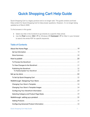
Quick Installation andOperation GuidePlease ReadContentsFeatures and Functions of the GRAFIK Eye QS . . . . . . . . . . . . . . . . . . . 2Wiring the GRAFIK Eye QSOverview of Line Voltage/Mains Wiring . . . . . . . . . . . . . . . . . . . . . . . . . . .Line Voltage Wiring Details . . . . . . . . . . . . . . . . . . . . . . . . . . . . . . . . . . . . .Overview of PELV (Class 2: USA) Wiring . . . . . . . . . . . . . . . . . . . . . . . . . .QS Link Control Wiring Details . . . . . . . . . . . . . . . . . . . . . . . . . . . . . . . . . .3467Completing Installation of the GRAFIK Eye QS . . . . . . . . . . . . . . . 8Programming ModeEntering and Exiting Programming Mode . . . . . . . . . . . . . . . . . . . . . . . . . . 9Navigating Menus in Programming Mode . . . . . . . . . . . . . . . . . . . . . . . . . 9Wireless Mode . . . . . . . . . . . . . . . . . . . . . . . . . . . . . . . . . . . . . . . . . . 10Zone SetupLUTRONAssign Load Types . . . . . . . . . . . . . . . . . . . . . . . . . . . . . . . . . . . . . . . . . . . 11Assign Non-Dim Load Type . . . . . . . . . . . . . . . . . . . . . . . . . . . . . . . . . . . . 11Setting Load Types . . . . . . . . . . . . . . . . . . . . . . . . . . . . . . . . . . . . . . . . . . 12The GRAFIK Eye QS control unit allows for control of bothlights and window treatments, without interfaces, using a singlecontrol unit. Features include pushbutton scene recall, infoscreen that displays energy savings and status, IR receiver,astronomic timeclock, contact closure input, and engravablebacklit buttons that are easy to find and operate.Scene Setup . . . . . . . . . . . . . . . . . . . . . . . . . . . . . . . . . . . . . . . . . . . . . . . . .Activate System Accessories . . . . . . . . . . . . . . . . . . . . . . . . . . . . . .Faceplate Removal . . . . . . . . . . . . . . . . . . . . . . . . . . . . . . . . . . . . . .Language Selection . . . . . . . . . . . . . . . . . . . . . . . . . . . . . . . . . . . . .Troubleshooting . . . . . . . . . . . . . . . . . . . . . . . . . . . . . . . . . . . . . . . . .Warranty, Contact Information . . . . . . . . . . . . . . . . . . . . . . . . . . . . .MLVZone Capacity GRK-6PCEQSGR-6PCE1 500 W2 000 W2 300 W1 500 VA / 1 200 W2 000 VA / 1 600 W2 300 VA / 1 800 W40 – 500 W40 – 500 W40 – 500 W40 – 500 VA / 40 – 400 W40 – 500 VA / 40 – 400 W40 – 500 VA / 40 – 400 WSee page 7 for PELV (Class 2: USA) ratings.EnglishEspañolFrançais1414141516For additional information, see the complete installation and operationguide at www.lutron.com/qsModel Numbers: Q SGRK-3PCE, QSGRK-4PCE, QSGRK-6PCEQSGR-3PCE, QSGR-4PCE, QSGR-6PCEAll units 230 V50/60 HzUnit Capacity (watts)13ItalianoDeutsch
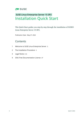
Features and Functions of the GRAFIK Eye QSHinged faceplateZone numbersZone raise/lower buttonsZone LEDs display currentlighting zone levels{1Optional Shade(window treatment) buttongroupsPreset and raise/lowerbuttons with integral LEDs(maximum of 3 buttongroups)Hinged faceplate23456OKTimeclock buttonDisplays currenttimeclock infoOK buttonUsed for programming,fade timeInfrared receiverFor handheld remote useInfo screenDisplays status orprogramming functionsMaster buttonsTemporarily raise and lowerlighting levels on unitScene buttonsWith integral sceneindicator LEDsUSB type mini BFor programming via PCFor additional information, see the complete installation and operation guide at www.lutron.com/qs GRAFIK Eye QS Quick Installation and Operation Guide 2
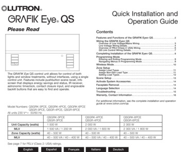
Wiring the GRAFIK Eye QS:Overview of Line Voltage/Mains Wiring1 2A B C1 2 3 41 2 3 4 5 6 L NLine Voltage/MainsCables and Load Wiring1 2 3 4 5 6 L NTerminal labels:L: Hot/LiveN: Neutral: Ground1-6: D immed/Switchedline voltage outputs230 VDistributionPanel ,0 mm (12 AWG)4each terminal2Incandescent loadLoad controlledby power modulePower moduleFor additional information, see the complete installation and operation guide at www.lutron.com/qs GRAFIK Eye QS Quick Installation and Operation Guide 3
Wiring the GRAFIK Eye QS: Line Voltage Wiring Details Use properly certified cable for all linevoltage/mains cables. Proper short-circuit and overloadprotection must be provided at thedistribution panel. Install in accordance with all local andnational electrical codes. PELV (Class 2: USA) terminals may betemporarily unplugged for ease of IR,occupancy sensor, and control wiring. Notice: Risk of damage to unit. Do notconnect line voltage/mains cable to PELV(Class 2: USA) terminals.Step 1: Install wallbox. Mount a 89 mm(3,5-in) deep 4-gang U.S. wallbox on adry, flat indoor surface that is accessibleand allows for system programming andoperation. Allow at least 110 mm (4,5 in)clearance above and below the faceplateto ensure proper heat dissipation. Allow25 mm (1 in) for faceplate overhang onall sides.Note: 4-gang wallbox available fromLutron; P/N 241400.Faceplate overhangswallbox on all sides;allow 25 mm (1,0 in)Step 2: Test load wiring. Turn power OFF at the circuit breaker orfuse box. Connect a standard light switch betweenthe live lead and load wire to test thecircuit. Turn power ON and check for short oropen circuits. If load does not operate,the circuit is open. If the circuit breakertrips (fuse blows or opens), a load shortmay exist. Correct short or open circuitsand test again. LUTRON110 mm(4,5 in)Hot/LiveSwitchLoadStep 3: Check control unit wiring. Earth/ground terminal connection mustbe made as shown in wiring diagrams(see page 3). Do not mix different load types on thesame zone. Follow all local and national electricalcodes when installing PELV (Class 2:USA) wiring with line voltage/mainswiring.WARNING! Shock hazard. Mayresult in serious injury or death.Always turn off circuit breaker orremove main fuse from power linebefore doing any work. Beforeconnecting the loads to theGRAFIK Eye QS control unit, testthe loads for short-circuits.NeutralLUTRONFor additional information, see the complete installation and operation guide at www.lutron.com/qs GRAFIK Eye QS Quick Installation and Operation Guide 4
Wiring the GRAFIK Eye QS: Line Voltage Wiring Details (continued)Step 4: Connect line voltage and loadsto control unit. Strip 8 mm (5/16 inch) of insulation off theline voltage/mains cables in the wallbox. 8 mm(5/16 inch) Connect the line voltage/mains, ground,and load wires to the appropriateterminals on the back of the control unit.L: Hot/LiveN: Neutral: GroundTerminals 1-6: Dimmed/Switchedline voltage outputsThe recommended installation torque is0,6 N m (5,0 in lbs) for line voltage/mainsconnections and 0,6 N m (5,0 in lbs) forthe earth/ground connection.Note: See page 12 for a list ofcompatible load types and instructionsfor programming the GRAFIK Eye QS toproperly recognise them.Notice: Risk of damage to unit. GRAFIK Eye QS control units must be in stalled by aqual i fied electrician in accordance with all applica ble reg u la tions and building codes.Im prop er wiring can result in dam age to control units or oth er equipment.Note: To avoid over heat ing and pos si ble damage to equipment, do not install controlunits to dim re cep ta cles, mo tor-op erated ap pli ances, or flu o res cent lighting notequipped with Lutron Hi-lume , Eco-10 , or Tu-Wire electronic dim ming ballasts, orother devices approved for your location. In dimmed magnet ic low-voltage cir cuits, youcan pre vent trans former overheating and failure by avoid ing excessively high currentflow. Do not op erate control units with any lamps re moved or burned out; re placeany burned out lamps immediate ly; use only transform ers that in cor po rate ther malpro tection or fused pri ma ry wind ings. Control units are de signed for res i den tial andcommercial use, for indoor use only.For additional information, see the complete installation and operation guide at www.lutron.com/qs GRAFIK Eye QS Quick Installation and Operation Guide 5
Wiring the GRAFIK Eye QS:Overview of PELV (Class 2: USA) Wiring1 2IR Wiring1,0 mm2 (18 AWG)each terminalFrom externalIR connection(by others)1: IR DATA2: IR COM1 2A B CA B C1 2 3 41 2 3 4Contact Closure Input Wiring1 2 3 4 5 6 L N1 2 3 4 5 6 L N1 2For settings, see the complete installation andoperation guide at www.lutron.com/qsA B CControl WiringCommon and power (terminals 1 and 2): Two 1,0 mm2 (18 AWG) each terminal1 2A B C1 2 3 41 2 3 4 5 6 L NTo control stations,window treatments,or other GRAFIK EyeQS control units1 2 3 41,0 mm2(18 AWG)eachterminalExample:Occupancy sensor(maximum 1)A: CCI SIGB: 24 VC: CCI COMData (terminals 3 and 4): Twisted, shielded pair 0,5 mm2 (22 AWG)each terminal1:2:3:4:COM24 V *MUXMUX* Do not connect terminal 2between any GRAFIK Eye QS andany other power supply, includingN H 1 2 3another GRAFIK Eye QS.See the complete installationand operation guide atwww.lutron.com/qs for detailedwiring example.Note: Use appropriate wire connecting devicesas specified by local codes.For additional information, see the complete installation and operation guide at www.lutron.com/qs GRAFIK Eye QS Quick Installation and Operation Guide 6
Wiring the GRAFIK Eye QS:QS Link Control Wiring Details System communication uses PELV (Class 2: USA)wiring. Follow all local and national electrical codes wheninstalling PELV (Class 2: USA) wiring with linevoltage/mains wiring. Each terminal accepts up to two 1,0 mm2 (18 AWG)wires. Total length of control link must not exceed610 m (2 000 feet). Make all connections in the control unit’s wallbox. Wiring can be T-tapped or daisy-chained. Wire sizes:- Two 1,0 mm2 (18 AWG) conductors for controlpower.- One twisted, shielded pair of 0,5 mm2 (22 AWG) fordata link.- Cable is available from Lutron:GRX-CBL-346S-500 (non-plenum) andGRX-PCBL-346S-500 (plenum). Checkcompatibility in your area. PELV (Class 2: USA) 24 V150 mA.LUTRONLUTRONSystem LimitsThe QS wired communication link is limited to 100 devices or 100 zones. Pleasenote the zone count and power draw unit information in the following table.QS DeviceZoneCountPower Draw Units(supplied)Power DrawUnits (consumed)330430630830163000100110(Refer to Spec.Submittal)Contact closure interface503Network interface002DMX interface0020(Refer to Spec.Submittal)00803-zone GRAFIK Eye QSLUTRONLUTRONLUTRONLUTRONLUTRONLUTRONLUTRON4-zone GRAFIK Eye LUTRON6-zone GRAFIK Eye QSLUTRONLUTRONLUTRONLUTRONLUTRONLUTRON8-zone GRAFIK Eye LUTRONLUTRONLUTRON16-zone GRAFIK Eye LUTRONLUTRONLUTRONseeTouch LUTRONLUTRONLUTRONInternational seeTouch LUTRONLUTRONLUTRONLUTRONLUTRONSivoia ONLUTRONLUTRONLUTRON5.262.501.063.75QS smart power panel4.26LUTRONT-Tap Wiring Example5.261.06QS link power supplyLUTRONLUTRONGRAFIK Eye QSseeTouch QSLUTRONDaisy-Chain Wiring ExampleQS smartpowerpanelLUTRONGRAFIK Eye QSSivoia QSLUTRONLUTRONLUTRONLUTRONseeTouch QSGRAFIK Eye QSSivoiaQSLUTRONLUTRONLUTRONLUTRONLUTRONLUTRONQS smartpower panelFor additional information, see the complete installation and operation guide at www.lutron.com/qs GRAFIK Eye QS Quick Installation and Operation Guide 7LUTRON
Completing Installation of the GRAFIK Eye QS1. Mount the control unit in the wallbox asshown using the four screws pro vid ed.Note: Follow all local and nationalelectrical codes when installing PELV(Class 2: USA) wiring with line voltage/mains wiring.2. Verify installation: Restore power. Press the top scene button. The LED willlight. Press the zone raise or lower button.Make sure the control unit is dimming allconnected loads.3. Apply the protective overlay to the controlunit. See the complete installation andoperation guide at www.lutron.com/qs forinstructions for naming zones.200 mm(7,9 in)87 mm(3,5 in)95 mm(3,75 in)WallNote: When tightening mountingscrews, make sure that the hingedcover and faceplate will open fully,as shown.Protective overlay(apply after installation)For additional information, see the complete installation and operation guide at www.lutron.com/qs GRAFIK Eye QS Quick Installation and Operation Guide 8
Programming ModeEntering and Exiting Programming ModeTo enter programming mode:Main menu2456Press and hold 1the topand3 bottomsceneTimeclockbuttons simultaneously for 3 seconds. TheScene setupLEDs in the scene buttons will scroll fromtop to bottom, confirming that you are inprogramming mode, and the info screen willdisplay the main menu.To exit programming mode:Scene 1Press and hold the top and bottom sceneFade timebuttons simultaneously for 3 seconds. The3 secondsinfo screen will go to Scene 1.Master buttonsOKOK buttonTimeclock (back) buttonPress and hold the top andbottom buttons for 3 secondsto enter or exit programmingmodeNavigating Menus in Programming ModeMaster ButtonsThe Master buttons allow you to move through the menuchoices. The current choice is highlighted on the info screen.OK ButtonThe OK button chooses the current highlighted menu choice.This will either take you to the next menu or accept a setting youhave selected. When the screen displays a Yes/No question, theOK button is “Yes”.Timeclock ButtonThe timeclock button functions as a “back” button duringprogramming mode. Pressing the timeclock button takes youback one step in the current menu. Pressing it repeatedlywill eventually return you to the main menu, but will not exitprogramming mode. When the screen displays a Yes/Noquestion, the Timeclock button is “No”.For additional information, see the complete installation and operation guide at www.lutron.com/qs GRAFIK Eye QS Quick Installation and Operation Guide 9
Wireless ModeMany models of the GRAFIK Eye QS support wirelesscommunication1234 with5 other6Lutron products. This feature allows for easy integration of wireless sensors, keypads,remotes, and window treatments for single-room wireless applications, as well ascompatibility with other Lutron wireless systems.Units supporting wireless communication have model numbers beginning with QSGRJor QSGRK.The wireless feature of the GRAFIK Eye QS Wireless control unit has three (3) modes ofoperation. Disabled: Use for wired-only systems. Enabled: The GRAFIK Eye QS Wireless control unit will respond to any programmingcommands from nearby Lutron QS wireless (and compatible) products. Ignore Programming (default): The GRAFIK Eye QS Wireless control unit will onlyrespond to normal operation commands from wireless devices programmed while inEnabled mode. To change the wireless mode of the GRAFIK Eye QS wireless control unit:1. Enter programming mode (see page 9).Main menu2. Use the Master buttons to highlight “Wireless Mode” and pressShade labelsthe OK button to accept.Wireless Mode3. Use the Master buttons to highlight the desired wireless mode,and press the OK button to accept.4. The info screen will display a confirming “Saved” message.Wireless Mode5. Exit programming mode (see page 9).EnabledMasterbuttonsOKOKbuttonTimeclock(back) buttonNote: The wireless signal has a range of 10 m (30 feet) throughstandard construction.SavedSavedFor additional information, see the complete installation and operation guide at www.lutron.com/qs GRAFIK Eye QS Quick Installation and Operation Guide 10
Zone Setup12Assign Load Types1. Enter programming mode (seeMain menupage 9).CCI Mode2. Use the Master buttons toZone setuphighlight “Zone setup” and pressthe OK button to accept.3. Use the Master buttons tohighlight “Load type”. PressZone Setupthe OK button to accept. SeeLoad Type“Setting Load Types” table onNon-Dim Load Typethe next page.4. Use the zone raise/lower buttonsto choose the load type for thatzone. See the list on the nextLoad Typepage for supported load types.Set zonesPress the OK button to accept.5. T he info screen will confirm thatyour load type has been saved.6. Exit programming mode (seepage 9).Saved3456MasterbuttonsOK123OK button456Use thezoneraise/lowerbuttons tochoose theload type forthat zone.Assign Non-Dim Load TypeZones assigned to non-dim loads have three available configurations: LOFO: Last On, First OffMain menu FOFO: First On, First OffCCI Mode FOLO: First On, Last OffZone setup Scenes made up of both dim and non-dimload types will toggle the non-dim loadsbefore the dim loads in a “First” on/offZone Setupconfiguration, and after the dim loads in a“Last” on/off configuration.Load Type1. Enter programming mode (see page 9).Non-Dim Load Type2. Use the Master buttons to highlight “Zonesetup” and press the OK button to accept.3. Use the Master buttons to highlight “Non-DimLoad TypeLoad type”. Press the OK button to accept.Set zonesSee “Setting Load Types” table on the nextpage.4. Use the zone raise/lower buttons to choosethe non-dim load type for that zone. (Zonesnot programmed as non-dim will be displayedas Unaffected.) Press the OK button toaccept.Saved5. T he info screen will confirm that your loadtype has been saved.6. Exit programming mode (see page 9).For additional information, see the complete installation and operation guide at www.lutron.com/qs GRAFIK Eye QS Quick Installation and Operation Guide 11
Zone Setup (continued)Setting Load TypesDirect control viaGRAFIK Eye QSControl viapower re load type Choose this load type from the menuon the GRAFIK Eye QS:IncandescentIncandescentMLV (magnetic low-voltage)MLVPower moduleELV (electronic low-voltage)—Power moduleHi-Lume /Eco-10 —Fluorescent moduleNon-dim load type—Non-dimNeon/Cold cathodeNeon, CCNeon, CCTu-Wire Tu-Wire Tu-Wire DMXDMX—RGB/CMY DMXRGB/CMY DMX—LUTRONPower moduleLoad Type Notes All electronic low-voltage(ELV) lighting used with aninterface must be rated for reversephase control dimming. Beforeinstalling an ELV light source,verify with the manufacturer thattheir transformer can be dimmed.When dimming, an ELV interface(such as the PHPM-PA-DV-WH)must be used with the controlunit. For all DMX or RGB/CMY DMXlighting, an external DMX interface(such as the QSE-CI-DMX) mustbe used with the control unit.Zone ratings:Maximum total lighting load per unit is 10 A.Not all zones must be connected; however, connected zones must have a minimum load of 40 W.No zone may be loaded with more than 500 W.Maximum total lighting load for a magnetic low-voltage (MLV) zone is 500 VA / 400 W.For additional information, see the complete installation and operation guide at www.lutron.com/qs GRAFIK Eye QS Quick Installation and Operation Guide 12
Scene Setup23 Group456Set Zone Levels, Fade Rates, and Shade (Window1 Treatment)Actions1. Enter programming mode (see page 9).Main menu2. Use the Master buttons to highlight “Scene setup” and pressTimeclockthe OK button to accept.Scene setup3. Use the Master buttons to highlight “Levels” to adjust lightingand/or window treatment levels. Press the OK button toaccept. Use the Master buttons to highlight the scene numberScene setupof your desired scene. Press the OK button to accept.Levels4. Set each zone to the desired light level for this scene usingLabelsthe zone raise/lower buttons. The info screen will display thezone and percentage as you adjust it. To set a zone as unaffected, lower the light levels all the wayScene setupto off, then hold the zone lower button for 3 seconds. Thescreen will display “---” and the three middle LEDs for thezone will be lit to indicate this zone is unaffected by the sceneScene 1(the zone will not change when this scene is initiated). When all zones are at the desired level, press the OK button toaccept.Scene 15. Use the Master buttons to set the fade time for this scene.Set zonesPress the OK button to accept.6. Note: This step is applicable only if you have window3 secondstreatments on your system. If you do not have or do not wishto set shade (window treatment) groups for this scene, pressthe OK button to skip this step.Scene 1Press the shade button that will take the window treatmentsAdjust fadeassigned to that button group to the level you want for this3 secondsscene. Repeat for any additional shade button groups. Pressthe OK button to accept. For window treatment programming,see the complete installation and operation guide atScene 1www.lutron.com/qs.7. The info screen will confirm that your scene has been saved.Set shadeGroups8. Exit programming mode (see page 9).MasterbuttonsOK123OKbutton456Shadebutton group123456Zone raiseZone lowerSavedFor additional information, see the complete installation and operation guide at www.lutron.com/qs GRAFIK Eye QS Quick Installation and Operation Guide 13
Activate System AccessoriesFaceplate RemovalLanguage SelectionOnce your GRAFIK Eye QS controlunit is programmed, you will need toactivate any accessories or interfacesthat are a part of the system. Refer to theinstructions included with those devicesto set them up for proper communicationwith the control unit.The faceplates may need to be removedto change the colour or to write in zonelabels. To remove either faceplate, openit fully (flush to the wall), and pull up (forthe top faceplate) or down (for the bottomfaceplate) to pull the hinges out of theirslots.Replace by sliding the hinges back intotheir slots.The GRAFIK Eye QS is capable ofoperating in the following languages:EnglishFrenchSpanishGermanItalianTo change the language to one of thesechoices, press the Timeclock buttonfour times, until the “Language” screenis displayed. (Note: Do not put the unitin programming mode.) Use the Masterbuttons to highlight your preferredlanguage, and press the OK button toselect and save.Pull up to removetop faceplate12345 6OK123456MasterbuttonsOKOKbuttonTimeclock(back) buttonPull down toremove bottomfaceplateFor additional information, see the complete installation and operation guide at www.lutron.com/qs GRAFIK Eye QS Quick Installation and Operation Guide 14
TroubleshootingSymptomPossible CausesRemedyUnit does not control loadsUnit does not turn lights onLEDs on front of unit are not ONCircuit breaker is trippingCircuit breaker is offLow zone settingsMiswireSystem short circuitSystem overloadSwitch circuit breaker onReprogram scenes to a higher intensityCheck wiringFind and correct shortsMake sure unit is not overloaded (see Zone Setup section)Unit does not control loadZone control does not workMiswireDisconnected wireBurned-out lampsCheck wiringConnect zone wires to loadsReplace bad lamps1 or more zones are “full on” when any scene ison and zone intensity is not adjustableMiswireShorted line outputMake sure loads are connected to the right zonesReplace control unitA Zone control affects more than one zoneMiswireCheck for shorts between zone outputsKeypad buttons are not workingMiswire or loose connection on QS linkKeypad LEDs are not trackingWallstation programming is incorrectTighten loose connections at PELV terminals on all units andother devices in the systemCheck the keypad function and programming on the unitsFaceplate is warmNormal operationSolid-state controls dissipate about 2% of the connected loadas heat.Unit does not allow scene change or zoneadjustmentsCannot program fade time from OffUnit in wrong save modeKeypad in system has locked the unitFade time from Off not programmable;can only program fade time to OffChange to correct save modeCheck programming and state of keypadsFade time from Off is always 3 secondsIntegral (direct-wired) contact closure input doesnot workMiswireInput closure/opening is not occurringUnit is in wrong CCI modeCheck wiring on contact closure inputCheck that the input device is opening and closing properlyChange to correct CCI modeTimeclock events do not occurSunrise or sunset events do not occur at thecorrect timeTimeclock is disabledTime is not set correctlyDate is not set correctlyLocation is not set correctlyHoliday schedule is in effectEnable the timeclockSet the timeSet the dateSet the latitude and longitude correctlyRemove the holiday schedule from your programmingFor additional information, see the complete installation and operation guide at www.lutron.com/qs GRAFIK Eye QS Quick Installation and Operation Guide 15
Contact InformationWarrantyLutron Electronics Co., Inc.One Year Limited WarrantyFor a period of one year from the date of purchase, and subjectto the exclusions and restrictions described below, Lutron warrantseach new unit to be free from manufacturing defects. Lutron will,at its option, either repair the defective unit or issue a credit equalto the purchase price of the defective unit to the Customer againstthe purchase price of comparable replacement part purchasedfrom Lutron. Replacements for the unit provided by Lutron or, at itssole discretion, an approved vendor may be new, used, repaired,reconditioned, and/or made by a different manufacturer.If the unit is commissioned by Lutron or a Lutron approved thirdparty as part of a Lutron commissioned lighting control system, theterm of this warranty will be extended, and any credits against thecost of replacement parts will be prorated, in accordance with thewarranty issued with the commissioned system, except that theterm of the unit’s warranty term will be measured from the date ofits commissioning.EXCLUSIONS AND RESTRICTIONSThis Warranty does not cover, and Lutron and its suppliers are notresponsible for:1. Damage, malfunction or inoperability diagnosed by Lutron ora Lutron approved third party as caused by normal wear andtear, abuse, misuse, incorrect installation, neglect, accident,interference or environmental factors, such as (a) use ofincorrect line voltages, fuses or circuit breakers; (b) failure toinstall, maintain and operate the unit pursuant to the operatinginstructions provided by Lutron and the applicable provisionsof the National Electrical Code and of the Safety Standardsof Underwriter’s Laboratories; (c) use of incompatible devicesor accessories; (d) improper or insufficient ventilation; (e)unauthorised repairs or adjustments; (f) vandalism; or (g) an actof God, such as fire, lightning, flooding, tornado, earthquake,hurricane or other problems beyond Lutron’s control.2. On-site labor costs to diagnose issues with, and to remove,repair, replace, adjust, reinstall and/or reprogram the unit or anyof its components.3. Equipment and parts external to the unit, including those soldor supplied by Lutron (which may be covered by a separatewarranty).4. The cost of repairing or replacing other property that is damagedwhen the unit does not work properly, even if the damage wascaused by the unit.EXCEPT AS EXPRESSLY PROVIDED IN THIS WARRANTY,THERE ARE NO EXPRESS OR IMPLIED WARRANTIES OF ANYTYPE, INCLUDING ANY IMPLIED WARRANTIES OF FITNESS FORA PARTICULAR PURPOSE OR MERCHANTABILITY. LUTRONDOES NOT WARRANT THAT THE UNIT WILL OPERATE WITHOUTINTERRUPTION OR BE ERROR FREE.NO LUTRON AGENT, EMPLOYEE OR REPRESENTATIVE HASANY AUTHORITY TO BIND LUTRON TO ANY AFFIRMATION,REPRESENTATION OR WARRANTY CONCERNING THE UNIT.UNLESS AN AFFIRMATION, REPRESENTATION OR WARRANTYMADE BY AN AGENT, EMPLOYEE OR REPRESENTATIVE ISSPECIFICALLY INCLUDED HEREIN, OR IN STANDARD PRINTEDMATERIALS PROVIDED BY LUTRON, IT DOES NOT FORM APART OF THE BASIS OF ANY BARGAIN BETWEEN LUTRON ANDCUSTOMER AND WILL NOT IN ANY WAY BE ENFORCEABLE BYCUSTOMER.IN NO EVENT WILL LUTRON OR ANY OTHER PARTY BELIABLE FOR EXEMPLARY, CONSEQUENTIAL, INCIDENTALOR SPECIAL DAMAGES (INCLUDING, BUT NOT LIMITED TO, DAMAGES FOR LOSS OF PROFITS, CONFIDENTIAL OR OTHERINFORMATION, OR PRIVACY; BUSINESS INTERRUPTION;PERSONAL INJURY; FAILURE TO MEET ANY DUTY, INCLUDINGOF GOOD FAITH OR OF REASONABLE CARE; NEGLIGENCE, ORANY OTHER PECUNIARY OR OTHER LOSS WHATSOEVER), NORFOR ANY REPAIR WORK UNDERTAKEN WITHOUT LUTRON’SWRITTEN CONSENT ARISING OUT OF OR IN ANY WAY RELATEDTO THE INSTALLATION, DEINSTALLATION, USE OF OR INABILITYTO USE THE UNIT OR OTHERWISE UNDER OR IN CONNECTIONWITH ANY PROVISION OF THIS WARRANTY, OR ANYAGREEMENT INCORPORATING THIS WARRANTY, EVEN IN THEEVENT OF THE FAULT, TORT (INCLUDING NEGLIGENCE), STRICTLIABILITY, BREACH OF CONTRACT OR BREACH OF WARRANTYOF LUTRON OR ANY SUPPLIER, AND EVEN IF LUTRON OR ANYOTHER PARTY WAS ADVISED OF THE POSSIBILITY OF SUCHDAMAGES.NOTWITHSTANDING ANY DAMAGES THAT CUSTOMERMIGHT INCUR FOR ANY REASON WHATSOEVER (INCLUDING,WITHOUT LIMITATION, ALL DIRECT DAMAGES AND ALLDAMAGES LISTED ABOVE), THE ENTIRE LIABILITY OF LUTRONAND OF ALL OTHER PARTIES UNDER THIS WARRANTY ON ANYCLAIM FOR DAMAGES ARISING OUT OF OR IN CONNECTIONWITH THE MANUFACTURE, SALE, INSTALLATION, DELIVERY,USE, REPAIR, OR REPLACEMENT OF THE UNIT, OR ANYAGREEMENT INCORPORATING THIS WARRANTY, ANDCUSTOMER’S SOLE REMEDY FOR THE FOREGOING, WILL BELIMITED TO THE AMOUNT PAID TO LUTRON BY CUSTOMERFOR THE UNIT. THE FOREGOING LIMITATIONS, EXCLUSIONSAND DISCLAIMERS WILL APPLY TO THE MAXIMUM EXTENTALLOWED BY APPLICABLE LAW, EVEN IF ANY REMEDY FAILSITS ESSENTIAL PURPOSE.TO MAKE A WARRANTY CLAIMTo make a warranty claim, promptly notify Lutron within thewarranty period described above by calling the Lutron TechnicalSupport Center at (800) 523-9466. Lutron, in its sole discretion, willdetermine what action, if any, is required under this warranty. To betterenable Lutron to address a
equipped with Lutron Hi-lume , Eco-10 , or Tu-Wire electronic dimming ballasts, or other devices approved for your location. In dimmed magnetic low-voltage circuits, you can prevent transformer overheating and failure by avoiding excessively high current flow. Do not operate control units with any lamps removed or burned out; replace