Transcription
Energy Boot Camp for BuildersBuilding Science and Changes to the Montana Energy CodeNew ConstructionPTCS Duct Sealing &Blower Door TrainingDecember 2013Presented by Dale Horton, ArchitectNational Center for Appropriate Technology1NCAT
AIR FLOW BASICS For air to move, you need a hole and a pressuredifference. Air always flows from high (or positive) pressure tolow (or negative) pressure. CFM in always equals CFM Out.2NCAT
What Is Pressure?NCAT
A Simple ManometerNCAT
A Simple ManometerNCAT
Examples of House Pressure Measurements Wind (Ave. 4 Pa)Stack Effect (1-3 Pa)Furnace plenum (120 Pa)Boot (5 Pa)Flue (-3 Pa)Bedroom with doors closed (up to 10 Pa)Room with a big exhaust fan (-20 Pa)House pressurized by blower door (50 Pa)Potential Back Draft Problems (-3 Pa)Source: PTCSNCAT6
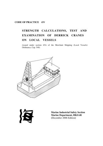
Typical Performance Testing EquipmentDigitalManometerBlower DoorFanDuct BlasterBlower DoorFrameExhaust FlowHoodPressure Pan7NCAT
The ManometerThere are several different typesof manometers: Energy Conservatory DG 700 Retrotec DM-2 Infiltec DM-4For PTCS trainings, we useEnergy ConservatoryEquipmentNCAT
Energy ConservatoryKey references for the discussion of performance testing are available on theweb at: Blower Door Operation Manual Quick Guide #DEP700-CR - 1 Point Depress Test with DG-700 Duct Blaster Operation Manual Quick Guide #PR700-CR - 1 Point Total Leakage Press Test with DG-700 Quick Guide #PR700 (Outside) - 1 Point Leakage to Outside Press Testwith DG-7009NCAT
The Digital ManometerMeasures the pressuredifference between twoareas.Input 1st areaReference 2nd areaNCAT
The Digital ManometerThe DG-700manometer alsohas 2 channels:Channel ANCATChannel B
The Digital ManometerThe Manometer Mantra:(“Input Nipple”) with reference to (“Ref Nipple”)(WRT)InputNCAT
DG700 TipsAlways Start With “Mode”Perform Baseline from leftto right on 3rd row ofbuttonsSource: PTCS13NCAT
The Digital Manometer Displays the difference inpressure between the inputand the reference. Does not display thedifference in pressurebetween channels.NCAT
Configuring the ManometerDEVICEDEVICEMODENCATMODETells manometer whatmeasurements to display(e.g pressure or flow)DEVICETells manometer whatequipment is being usedCONFIGTells manometer what theequipment configuration is(ring number)CONFIG
Configuring the Manometer - MODETell it what you want to readModeNCATPR/PRMeasures the pressure difference between “input”and reference on both channels A and BPR/FLMeasures the amount pressure recorded onchannel A, and the amount of air flowingthrough device on channel BPR/FL@50Calculates the amount of air that would flowthrough device on channel B if pressure onchannel A was 50 Pa. (for homes only)PR/FL@25Calculates the amount of air that would flowthrough device on channel B if pressure onchannel A was 25 Pa. (for ducts)
Configuring the Manometer - DeviceTell it what you’re connected toDeviceNCATBD3Blower Door Model 3DB ADuct Blaster Model A (White Fan)DB BDuct Blaster Model B (Black Fan)TF, EXH,BD4, etc.TrueFlow Plate and other Energy ConservatoryEquipment.
Configuring the Manometer - ConfigTell it how big the hole is (whatring)ConfigNCATOpenOpen fan, no ring attachedA1Ring A (Blower door); Ring 1 (Duct Blaster)B2Ring B (Blower Door); Ring 2 (Duct Blaster)C3Ring C (Blower Door); Ring 3 (Duct Blaster)
List of Performance Tests in Action Order1. Dominant Duct Leakage Test2. Room Zonal Pressure Difference Test3. Combustion Appliance Zone Test4. Blower Door Test*5. Zonal & Pressure Pan Tests w/ BD fan6. Total Duct Leakage Test*7. Duct Leakage to the Outside Test*8. Exhaust Fan Flow Test* - Indicates test related to code19NCAT
PTCS Duct Training – New ConstructionDominant Duct LeakageNot a Code Required TestPTCSPerformance TestedComfort SystemsNCAT
NCAT
NCAT
PTCS Duct Training – New ConstructionRoom Zonal PressureDifferenceNot a Code Required TestPTCSPerformance TestedComfort SystemsNCAT
Room Zonal Pressure TestThe NWESHprogram requiresthat the pressurebetweenbedrooms andcommon area betested to assurethat the pressuredifference in nomore than 3 Pa.24NCAT
Zonal Pressure TestMeasure pressuredifference betweenroom and central zoneof home.What is the pressure inthe room WRT thecentral zone? -25NCAT
PTCS Duct Training – New ConstructionCombustion ApplianceZone TestNot a Code Required TestPTCSPerformance TestedComfort SystemsNCAT
What’ A CAZ?Any zone in the house , including the garage, thatcontains a vented combustion applianceNCAT
Causes of CO in Homes Urban TrafficCars started in garagesUnvented combustion equipmentBackdrafting combustion equipmentFailed heat exchangersReally dumb stuff (barbecuing indoors, running generatorsindoors etc If there is Combustion there might be CONCAT
Carbon Monoxide (CO)NCAT
Carbon Monoxide (CO)NCAT
Unvented Combustion Equipment - Not SafeNCAT
NFPA Standard 54 Combustion Venting CategoriesClass INegative Pressure VentingNon-CondensingClass IINegative Pressure VentingCondensingClass IIPositive Pressure VentingNon-CondensingClass IVPositive Pressure VentingCondensing32NCAT
Why Category I Appliances VentNCAT
The Driving Forces That Change Air Pressure in a House NCATWindStack (the Chimney effect)Exhaust FansDuct leakageUnbalanced forced air systems (interior door closure)
Stack Effect: The most persistent consistent pressure effect.PositivePressureNeutral PressurePlaneNegativePressure35NCAT
Wind Driven PressuresWind createspositive andnegative pressureswithin the house.Wind ureExfiltration36NCAT
The Two Paths of Air in a FurnaceHouseAirThe HVAC fanis the drivingforce thatmoves the airin the house airpathNCATCombustionAirBuoyancy isthe drivingforce thatmoves the airin thecombustion airpath
Correct Venting, Gas water Heater Venting SuccessfullyNCAT
Large Kitchen Fan Backdrafting Gas Water HeaterNCAT
Good VentingNCAT
Bad Venting BackdraftingNCAT
Home Appliance Induced DepressurizationNCAT
Beware of Over Sized Fans Tim Allen “More Power”Kitchen fans are sometimesrated at 1,200 CFM. Installed in a commercialenvironment, code wouldrequire make up air.NCAT
Exhaust FansThe Water Heater is -3PaWRT to House-3When the pressure in the flueis negative with respect to theCAZ, successful ventingoccurs (air moves from highto low pressure)NCAT0
Large Kitchen FanBackdrafting Gas WaterHeater 3 -5When the pressurein the flue is positivewith respect to theCAZ backdraftingoccurs. (air movesfrom high to lowpressure)NCAT
SUPPLY LEAKINSIDE HOUSE-4Supply LeakNCAT 5PressurizedCAZ
RETURN LEAKINSIDE CAZReturn leak 3 -5Depressurized CAZNCAT
RETURN LEAKOUTSIDE HOUSE-4 6Pressurized CAZNCAT
SUPPLY LEAKOUTSIDE HOUSE 4 -6Depressurized CAZNCAT
CAZ TestNCAT
Setting Up the CAZ TestIf zone behind closed door isPositive WRT CAZLeave door closedCAZNegative WRT CAZOpen doorCAZ -51NCAT
Fixing The Problem Make more holes in thehouse Push more air into thehouse Suck more air out of theventing system Get rid of the backdrafting appliance Get rid of the source ofdepressurizationNCAT
Removing the Source of Depressurization Seal holes in top ofbuilding Seal return duct leaks inthe CAZ Seal supply leaksoutside the envelope ofthe house Eliminate high speed onoversized kitchen fansNCAT
Combustion Appliance Zone Pressure Test ExampleBaseline in CAZAir Handler OnBasement Bath Fan1st Floor Bath FanKitchen Fan2nd Floor Bath FanClothes Dryer-3 Pa-4 Pa-6 Pa-8 Pa-14.5 Pa-17 Pa-19 PaAdjusted-1 Pa-3 Pa-5 Pa-11.5 Pa-14 Pa-16 Pa54NCAT
House Depressurization Limits (HGL) Per ECAppliance TypeDepressurization LimitsIndividual Natural Draft Water Heater (WH)2 PaNatural Draft WH & Natural Draft Furnace or Boiler3 PaNatural Draft WH & Induced Draft (ID) Furnace/Boiler5 PaIndividual Natural Draft Furnace/Boiler5 PaIndividual ID Furnace/Boiler15 PaPower Vented & Sealed Combustion Appliances 25 PaFrom the Minneapolis Blower Door Operation Manualpublished by the Energy Conservatory55NCAT
PTCS Duct Training – New ConstructionBlower Door TestA Code Required Test(for all homes)PTCSPerformance TestedComfort SystemsNCAT
The Blower DoorBlower DoorMeasure how much airleaks through cracks andductsIf the fan is blowing 2,000cfm out of the house, andit’s staying at the samepressure (-50 Pa), there mustbe 2,000 cfm of air leakingthrough holes in the houseSource: PTCSNCAT57
Typical House Tightness LevelsOlder HomesTypical New Home 20002009 IECC Tightness Limit Zone 6Montana State Energy CodeProposed MT State Energy CodeEnergy Star HomesIdaho New Homes 20132012 IECC Tightness Limit Zone 6ACH5010 774443.63CFM2000 SF 260018001800105010501050930800Example based on 2,000 Ft2 house with n 14.5.58NCAT
The Blower Door Parts - RingsRing AFanCoverNCATRing BFan(no ring open config)
The Blower Door – The SkinHose EyeletsNCAT
Blower Door Parts – the Pressure Sensor RingPressure sensor on front side offanManometer measures pressuredifferenceThe higher the pressure drop, thebigger the flowGiven the same configuration(ring size) the higher the pressure,the bigger the flowHigher Pressure More FlowNCAT
The MeasurementNCAT
Pressurizing the HousePressure x hole size flowThe larger the opening, the greater the flow.NCAT
Safety Mandates1. Do not use the blower doorif you see one of these! Fire (Pressurize thehome blast furnace) Ash (Depressurize thehome ashes spread)2. All gas appliances(combustion furnaces andwater heaters) must be off(set it to pilot)3. House should be inspectedfor potential asbestoscontaminationNCAT
Blower DoorNCAT
One-point and Multi-point Blower Door Test Procedures(assumes DG-700) Perform baseline measurement (with fan sealed) Choose and install appropriate flow ring Select Device in DG-700 (i.e., BD-3) Select flow ring configuration in DG-700 (i.e., A1)For One-point Test choose a mode setting of PR/FL@50,increase fan speed until channel A is to within 5 Pa of 50,Channel B will display the one-point leakage estimate.For Multi-point test take readings such as 60, 50, 40, 30Pa, use Tectite software to correlate data, use duringwindy periods or if greater accuracy is desired.66NCAT
Blower Door De-pressurization TestTo FanTo Outside67NCAT
Can’t Reach Fifty FactorFor DG-700 users, adjustment is made automatically ifperforming a one point test in PR/FL@50 modeFor DG-3 users if you can’tdepressurize house to 50 Pawith an open fan then adjustmeasured air flow with CRFExample: House can only bedepressurized to 28 Pa withmeasured fan flow of 5,600CFM.CRF 1.46 so adjusted flow is5,600 x 1.46 8,176 CFM68NCAT
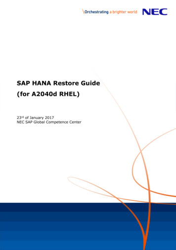
Blower Door MathTo calculate air changes per hour at 50 Pa:ACH50 CFM50 x 60House VolumeThe volume is cubic feet enclosed by the conditioned space boundary.To convert air change rate at 50 Pa to the air changerate at natural conditions:ACHnat CFM50 x 60n x House Volumen – The correlation factor shown on the following slide.69NCAT
Converting CFM50 toAir Change Values(Provides Approximate Values)70NCAT
Leakage Area EstimatesAn alternative means of quantifying building tightnessis to estimate the leakage area associated with aspecific air flow.House Air Leakage Area Estimates1. Divide CFM50 by 10 to get square inches ofleakage area. (Simple but approximate)2. Use TECTITETM software from the EnergyConservatory with multi-point blower door test.71NCAT
PTCS Duct Training – New ConstructionZonal and PressurePan Test w/ BD FanNot a Code Required TestPTCSPerformance TestedComfort SystemsNCAT
Zone Pressure TestingSet Up: Set up house for basic blower door test.NCAT
Zone Pressure TestingNCAT
Read Zone PressureExample: This Air handler (AH) is totally outside theconditioned area of the house.NCAT
House WRT outsideNCAT
House WRT outsideNCAT
House WRT AtticNCAT
House WRT AtticNCAT
Room A wrt Room BNCAT
Supply ducts wrt houseNCAT
House wrt atticNCAT
Room A WRT Room BNCAT
Room A WRT Room BNCAT
Pressure Pan Test50 PA-50 PANCAT
Pressure Pan Test45 PA-50 PANCAT
Pressure Pan Test5 PA-50 PANCAT
Pressure Pan Test25 PA-50 PANCAT
PTCS Duct Training – New ConstructionTotal Duct LeakageA Code Required Test(for some homes)PTCSPerformance TestedComfort SystemsNCAT
Duct Blaster PartsThe SnorkelThe RingsNCATThe Fan
Flow Pressure x Size of HoleYou control the pressurewith the fan speedcontroller.The rings change the sizeof the hole.NCAT
Ring CFM CapacityFan Configuration Flow Range (cfm) for Series B DB NCATOpen (no ring)Ring 1Ring 2Ring 31,500 – 600 cfm800 – 225 cfm300 – 90 cfm125 – 10 cfm
Total Duct Leakage TestDuct blasterblows air into ductsystem (increasespressure)Air blows out theleaks in thesystem (registersare blocked)Air blowing in has tobe blowing out (leaks)NCAT
Total Duct Leakage TestNCAT
Total Duct Leakage Set Up Side A measuresduct pressure Side B measuresfan pressure, andmanometerreflects it as CFMNCAT
Attaching to the Return GrilleNCAT
Attaching to the Air HandlerNCAT
Direct Attachment to the Air handlerNCAT
Steps for Total Duct Leakage Test1. Seal Registers, RemoveFilters2. Connect duct blaster3. Insert Pressure probe inone of the registers4. Configure Manometer5. Connect hose fromregister to manometer,and fan pressure fittingto the manometerNCAT
Total Duct Leakage TestNCAT
Total Duct Leakage TestNCATPTCS
Can’t Reach Pressure (CRP) Correction FactorsExample: The results of the test show a leakage area of 275 CFM at a ductpressure of 35 Pa. The correction factor for a pressure of 35 Pa is 1.26.275 CFM35 X 1.26 346.5 CFM50The test doesn’t give any indication of where to find the holes, just anestimate of the collected hole size. As CFM50 values get larger, they will tendto be less accurate.Can’t Reach Pressure (CRP) Correction FactorsReferenceCRP FactorPressure50 NCAT
Total Duct Leakage TestInterpreting Results:The CFM50 is a measure of the total collected hole size in the system. Asan approximation the CFM50 divided by 10 gives the total effectiveleakage area in square inches.Example: 400 CFM50/10 40 square inches of total leakage area.Using this approximation during sealing can help estimate how manyand how big the holes are that you are looking to seal.NCAT
PTCS Duct Training – New ConstructionDuct Leakage to the OutsideA Code Required Test(for certain homes)PTCSPerformance TestedComfort SystemsNCAT
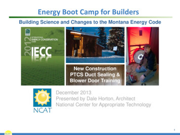
Duct Leakage to the ExteriorSource: NCATStandard New Construction: For certification, the measured CFM50 must not exceed0.06 CFM50 x floor area served by the system (in square feet) or 75 CFM50 whicheveris greater.NCAT
NCAT
NCAT
Exhaust Fan Flow TestLong or crimpedexhaust fan ductscan significantlyreduce actualexhaust flow.Not a Code Required Test108NCAT
PTCS New Construction Duct Leakage LimitsAllowable Leakage 0.06 CFM50 x conditioned floorarea or 75 CFM50, whichever is greater.Example 1: What is the duct leakage limit for a 1000 SFhouse?0.06 CFM50 x 1000 SF 60 CFM, but since 75CFM50 is greater the allowable leakage is 75 CFM50Example 2: What is the duct leakage limit for a 3000 SFhouse?0.06 CFM50 x 3000 SF 180 CFM which is greaterthan 75 CFM so the allowable leakage is180 CFM109NCAT
PTCS Minimum Ventilation LevelMVL Based on known occupancy:MVL (# of occupants) x (15 cfm/occupant)MVL Based on bedrooms:MVL (3 of bedrooms 1) x (15 cfm/bedroom)MVL Based on ACH and VolumeMVL (0.35 ACHnat x House Volume in ft3) / 60 minutesMost Restrictive Should be Applied.110NCAT
NCAT 9 Key references for the discussion of performance testing are available on the web at: Blower Door Operation Manual Quick Guide #DEP700-CR - 1 Point Depress Test with DG-700 Duct Blaster Operation Manual Quick Guide #PR700-CR - 1 Point Total Leakage Press Test with DG-700 Quick Guide