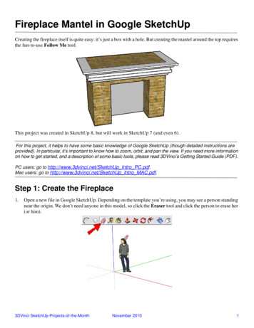
Transcription
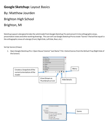
Google Sketchup: Layout BasicsBy: Matthew JourdenBrighton High SchoolBrighton, MISketchup Layout is designed to take the solid model from Google Sketchup Pro and convert it into orthographic views,presentation views and other working drawings. The user will use Google Sketchup Pro to create “Scenes” that will be equal t othe orthographic views of a design (Front, Right Side, Left Side, Rear, etc.)Set Up Scenes (Views)1. Open Google Sketchup Pro Open House Tutorial “Last Name” File Select Scenes from the Default Tray (Right Side ofthe Screen)MenuCreates a Snapshot of thecurrent orientation of themodelView Shown asThumbnails or ListHide DetailsSceneDetails
2. Set the followinga. Set Orientation of House to Top ViewNOTE: Be sure the Camera Setting is set to Parallel Projection; this can be found in Camera drop down menub. View Pull Down Menui. Turn Off Axisc. Tagsi. Turn ON1. Walls2. Plan Dimensions3. Doors4. Windowsd. Right Hand Toolbar Select Styles Tab Set the FollowingStyles allow the user to create a series of settings to show the model (i.e. Hidden, Solid, Render, etc.)Starting we will use the default Style 1i. Select Create a Drop Down Menu next to In Model Select Photo Modeling Photo Modeling Style Turn OFF Axis Lines (Drop Down Menu View Axis (Uncheck it)Drop Down Menu Photo Modeling Select Photo Modeling Styleii. Select Down Arrow Next ot Straight Lines Select In ModelSelect Down Arrow Select In Modeliii. Sections May Activate Turn them offSections ActiveSelect Section Icons to Turn OFFModel without Section
iv. Scene is added to the In Model selectionKeep Straight Photo Modeling SelectedSelect Photo Modelingv. Select Edit TabSelect Edit1. Display WireFrame Mode:Makes all lines Object Lines(including hidden lines)2. Display in Hidden Line Mode:Makes all unseen edgeshidden lines3. Display in Shaded Mode:Shows materials/colors onobjects. (Default State forsoftware)4. Display Shading withTextures: Allow user tosimulate material textures5. Display Shaded Using AllSame: applies same shadingcolor for all objectsRendering OptionsNote: User can Switch Back to Rendered Image by Selecting Scenes Select In Model SelectArchitecture Style 1
1. Select Display Wireframe2. Select Face Settings Change Color to Black Style Select Display Wireframe Modea. Drawing should look as follows
3. Select Display in Shaded Modea. Do the followingi. Check Groundii. Change Color to White (Select the color Box drag the last color option to white)Select DisplayShaded ModeCheckGroundColorSelect White ColorBox Change L colorto White (drag all theway to the right)3. Creating a Style (View)a. Rotate Model to Top View ()Select Scenes Tab on the Right Hand Toolbox Select Sign Pop-UpMenu Select Save as a new style (other options are designed to update views as model is modified) SelectCreate SceneSelect Sign tocreate Scene1. Select Save as a new style2. Select Create Scene
b. Rename Scenei. Select Scene At the Bottom of the Scene Menu Change Name to FLOOR PLAN4. Repeat the Steps to Create new Scenes for the followinga. Turn On Roof Tag before creation of Sceneb. Turn OFF Plan Dimensions Tagc. Rename the same for the Elevation that is showingd. Style will be Display Textures Modee. Scenes Rotate view to proper elevationbefore creation of Scenei. FRONT ELEVATIONii. RIGHT ELEVATIONiii. LEFT ELEVATIONiv. REAR ELEVATIONv. Pictorial (3D ViewScenes: Total 5
f.Rendered Scenei. Scenes Tab Select Tab In Model Option Select Architecture Style 02ii. Add Materials like siding and wood to the fascia boardiii. View setting Isometric or a rotational pictorial view (see below) to show overall features of the houseiv. Axis and Sections Turned OFFv. Name: Pictorialvi. Change Background to WhiteSelect EditSelect EditSelect Color Boxvii.NOTE: 6 Total Scenes are created
SAVE FileSketchup LayoutScenes created in Sketchup Pro will be imported into Layout. Layout and Sketchup Pro will be linked together so if amodification of the house in Sketchup Pro will be updated in Layout.1. Open Layout Program Select More TemplatesSelect MoreTemplates2.3. Select Title BlocksSelect MoreTemplates
4. Select Contemporary A3 Landscape5. Layout WorkspaceTabs shows created sheetsin a packet of plansTitle Block Edit by doubleclicking on Item and Type info orgo to Drop Down Menu File Document Setup Fill in Fields
Colors: add colors/materials to geometryShape Style:Pattern Fill: Adds 2D Crosshatching to ViewsSketchup Model: Imports Scenes from SketchUp ProScaled Drawing: Create 2D Drawings using 2D ToolsDimension Style: Dimension 2D DrawingsText Style: Adjust TextPages: Lists Sheets in the Packet of PlansLayers: Assign 2D Geometry to Layers (Tags)Scrapbooks: Add Rendering techniques to viewsInstructor: Tutorial Guide6. Document Setup: This will fill out the title block automatically for all sheetsSelect Drop Down Menu File Select Document Setup Fill out Auto Texta. Address: BHS Addressb. Author: TYPE “YOUR NAME”c. PROJECT Name: TUTORIAL SKETCHUP BASICS
Set Units to Inches7. Creating Sheetsa. Select Tool Tray Pagesb. Select Inside Pages Right Click Select Rename Rename to FLOOR PLANc. Select Sign (New Sheet) Rename EXTERIOR ELEVATIONSd. Select Sign (New Sheet) Rename ROOF PLAN
8. Cover Pagea. Adding Viewsi. Select Pages Select Cover Pageii. Adding View: Select Drop Down Menu File Select Insert Navigate to Tutorial Sketchup “YourName” OpenBy Default the Layout will Pictorial. Within this window the user can rotate the image by placing cursor in thewindow Hold Middle Mouse Button Down and Rotate
iii. Setting Info Select Tab Sketchup ModelSet Scene fromSketchup ProRefresh Views fromSketchup ProLock ViewSet Standard Orthographic ViewsFront, Top, R.S, L,S, BackAdd Rendering OptionsLine Setup fromRenderd to WireframeScale setup to ameasured size.
iv. Set the Following1. Scene: Pictorial2. Scale 3/8” 1’-0”3. Adjust Frame as neededCenter Arrows Adjust Size ofView Box Hold Left MouseKey Down and DragCorners manually adjust scalePlace View on the left hand side of the workspace
v. Table of Contents1. Select Table Tool2. Left Click on the workspace Drag Mouse to place number of Rows and Columnsa. Set Chart with 2 Columns and 5 Rowsb. Left Click to Place number of columns/rowsc. Drag Mouse to set size of cellsLeft Click to start the Table Drag to 2 Columns and 5 Rows Left Click to SetDrag Cursor to set thesize of the cells LeftClick to set size3. Fill out the Cell with the followingNOTE: Top two cells are merged: Select both cells (Double Click on a cell to activate HoldShift) Right Click Select MergeNOTE: Click on Text Style Tab from the Default Tray to set Center Justification or change fontheight/stylevi. Final Cover Page Layout
9. Sheet Floor Plana. Select Pages Tab from the Default Tray Select Floor Plan Sheetb. Select Drop Down Menu Insert Navigate to Tutorial Sketchup Tutorial Basics “Student Name” SelectOpenc. Set the followingi. Scene: Floor Planii. Scale: 3/8” 1’-0”iii. Set the following Door and Window Labelsiv. Create Window and Door Schedules as shown.
10. Repeat the Above Steps on Sheet Exterior Elevationsa. Place all Four Elevations on the Page with Titles
11. Roof Plana. In Sketchup Pro Create 3 Scenes with the Roof Turned Oni. Top, Right and Frontii. Display Type Hidden Line Modeb. Save Adjustments in Sketchupc. Return to Layout Insert Navigate to the File May have to update file once placed so current settings arelocked inUpdate Icon
Crop ViewSketchUp Model Tab Select Preserve Scale on Resize Then resize imaged. Place the FollowingViews and DimensionsUse Label Tool1.2.3.4.Left Click feature to point atLeft Click Start of Horizontal Line3. Left Click End of Horizontal LineType TextSave LayoutSubmission: Print out all four sheets Staple and Turn In
The user will use Google Sketchup Pro to create "Scenes" that will be equal to the orthographic views of a design (Front, Right Side, Left Side, Rear, etc.) Set Up Scenes (Views) 1. Open Google Sketchup Pro Open House Tutorial "Last Name" File Select Scenes from the Default Tray (Right Side of the Screen) Creates a Snapshot of the