Transcription
Spine: 1.10"CD-ROM Included!Value-Packed CD-ROM Explore the user interface and learn SketchUp tools and shortcuts Master objects, drawing, modeling, effects, and the art of modification Combine 3D models with 2D images using the LayOut tool Browse 3D Warehouse for components and models Export your SketchUp projects to Google Earth Extend functionality with Ruby scripting and plug-insWhat’s on theCD-ROM?Check out the CD for a trial versionof SketchUp 7 Pro, as well as yourown free copy of Google SketchUp 7.You’ll also find most of the 3D modelsfrom the book, so you can follow thetutorials and gain hands-on practicein the techniques.System Requirements: See the CD appendixfor details and complete system requirements. Jump into SketchUp by designing a windmill right off the bat Why scribble on a notepad when, with a few computerstrokes, you can create 3D drawings in SketchUp andcapture your best ideas in software? With the step-by-stepinstruction in this in-depth guide, you’ll soon bemodeling your ideas like a pro, from designing buildingsto drawing room layouts or planning landscaping.Whether you’re brainstorming ideas, preparing a formalpresentation, or finalizing a project to upload to GoogleEarth, this is the SketchUp book you need to succeed.Google SketchUp and SketchUp Pro 7Create professional-quality drawingsand models in SketchUp Free version of Google SketchUp 7 Trial version of Google SketchUp Pro 7 Chapter example files from the bookKelly L. MurdockGoogle SketchUpand SketchUp Pro 7 Rotate the camera withthe Look Around toolwww.wiley.com/compbooksView layers by colorDesign a building andput it on Google Ear th Once placed, the texture isfrozen to the selected faceShelving Category:COMPUTERS / Computer Graphicsand Image ProcessingReader Level:Beginning to Advanced 39.99 USA 47.99 CanadaMaster SketchUp Pro 7’stools and featuresMurdockCapture your bestideas in SketchUpThe book you need to succeed!
Modeling BasicsIN THIS PARTChapter 9Drawing in SketchUpChapter 10Modifying ObjectsChapter 11Adding TextChapter 12Using the Construction ToolsChapter 13Matching a Background PhotoChapter 14Working with TIN Surfaces
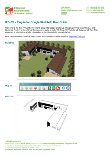
Drawing in SketchUpSketchUp is designed to let you turn simple sketches into 3-D scenes.This chapter presents the tools used to create many of the simple basicelements that make up a project.SketchUp includes a number of tools (which happen to be called drawingtools) that help you sketch perfect circles, arcs, and straight lines. Usingthese tools, your sketches can become drawings.IN THIS CHAPTERUnderstanding the drawingaxesDrawing lines and facesDrawing arcsUnderstanding the Drawing AxesThe key to working in 3-D is to keep track of the axes. The standard axes arelocated at the origin of the drawing area, as shown in Figure 9.1. These axesare color coordinated with red denoting the X-axis, green marking theY-axis, and blue indicating the Z-axis.If you find that the axes are in the way when you print the model, you canturn them off by choosing View Axes. This is a toggle command that simply hides and unhides the axes.165Drawing freehand and erasingcurvesDrawing shapesSetting drawing preferences
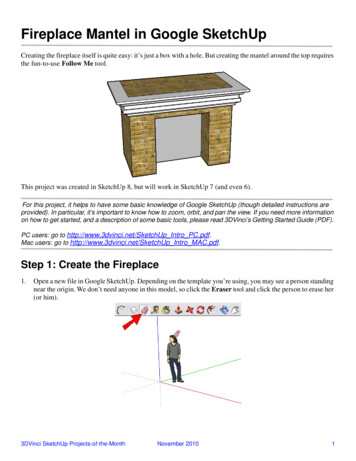
Part IIIModeling BasicsFIGURE 9.1The default axes help keep the correct orientation.Z-axisY-axisX-axisDrawing Lines and FacesDrawing is accomplished by dragging in the drawing area with one of the various drawing tools.The simplest drawing tool is the Line tool, which looks like a pencil in the Getting Started toolbar.You can select this tool from the Draw Line menu command (L) or by selecting it from theGetting Started Toolbar. You can draw straight lines from point to point with this tool.When dragging with the Line tool, the line turns red, green, or blue when the line is aligned withone of the axes. This makes it easy to sketch and connect lines together to form faces.Three or more lines that are connected and that exist in the same plane form a face. When a face iscreated, it is automatically shaded gray, as illustrated by the triangle in Figure 9.2.166
Drawing in SketchUpFIGURE 9.2A minimum of three edges are required to define a face.CROSS-REFIf you need some help drawing lines, you can set some guidelines using the TapeMeasure tool, which is covered in Chapter 12.When drawing a line, the line’s length is displayed in the Measurements Toolbar. If you type avalue in the Measurements Toolbar while drawing a line, then a line of that length is drawn.Alternatively, you can type three coordinates in the Measurements Toolbar and a line is drawnfrom the starting point to the specified coordinate position.Understanding inference positionsWhen you drag over the top of objects within the drawing area, you may have noticed that the pointlocated at the tip of the Line tool changes color based on where the mouse cursor is located. Thesepoints identify specific locations and are used to help you draw accurately by giving you a visualclue as to where the cursor is located. This feature is called inference and the key to using inferenceis to learn what the different colors indicate. SketchUp identifies the following inference points:1679
Part IIIModeling BasicsIf you hover with the mouse cursor over an inference point, a tooltip appears identifying the inference point.TIPn Endpoints: Endpoints appear at each end of a line entity and are identified by a greenpoint.n Midpoints: Midpoints appear directly in the middle of a line entity and are identified bya cyan point.n Intersections: Intersections appear where one line entity crosses another line entity andare identified by a black point.n On Edge: On Edge points appear anywhere along the edge of a line entity and are identified by a red point.n On Face: On Face points appear anywhere on the surface of a face entity and are identified by a blue point.Figure 9.3 shows each of these various inference points along with their tooltips.FIGURE 9.3Inference points are identified by colored points and tooltips.In addition to specific points, lines can also be lined up using inference. Lines that use inferenceare displayed as solid colored lines or as dashed colored lines, depending on the inference type.Tooltips also appear above the various inference lines if you hold the mouse still. Inference canrecognize the following lines:n On Red Axis, On Green Axis, On Blue Axis: Lines that are aligned to a specific axis aredisplayed in the color of the axis that it is aligned with: red for the X-axis, green for theY-axis, and blue for the Z-axis.168
Drawing in SketchUpn From Point: If the endpoint of a line is positioned so that it has the same X, Y, or Z-axisvalue as another point in the scene, then a dashed line connecting the two points isdisplayed.n Perpendicular to Edge: When a line is perpendicular to another line, a magenta line isdisplayed. Perpendicular lines have a 90-degree angle between them.n Parallel to Edge: When a drawn line is parallel to an existing line, the line is also displayed in magenta.Figure 9.4 shows each of these various inference lines along with their tooltips.FIGURE 9.4Inference lines are also identified by colored lines and tooltips.Constraining inferenceAs a model gets more and more complex, getting the right inference can be tricky. If you find theright inference, you can constrain the line to the selected inference using the Shift key. For example, if you are creating a line that is perpendicular to the midpoint of an edge, then drag out fromthe midpoint until the Perpendicular to Edge inference is identified and press and hold the Shiftkey. The line remains constrained to be perpendicular as you continue to drag with the Line tool.Tutorial: Building a hexagon towerFor this example, I created three hexagon shapes that are vertically aligned. The goal is to drawlines between the corner points of these hexagons using inference. The result will be a nice hexagon tower.1699
Part IIIModeling BasicsTo connect three vertically aligned shapes, follow these steps:1. Open the Hexagon tower.skp file from the Chapter 09 folder on the CD. This fileincludes three vertically aligned hexagons.2. Select the Line tool (L). Move the mouse cursor over one of the corner points on thebottom polygon shape. Notice how a green point appears indicating that the point is anendpoint. Click on the highlighted endpoint and move the mouse cursor to the cornerpoint above and to the right of the clicked point. Click again on the corner point aboveon the third polygon, then press L to deselect and reselect the Line tool.3. Repeat Step 2 for each set of corner points around the polygon. Figure 9.5 shows theresulting tower.FIGURE 9.5Using inference makes it easy to draw lines between specific points.170
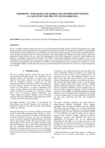
Drawing in SketchUpDrawing ArcsArcs are drawn with the Arc tool. This tool is located in the Draw Arc menu (A) or on theGetting Started Toolbar. It works by clicking to specify where the two endpoints of the arc arelocated and then dragging to curve the arc between the two endpoints.While the Arc tool is active, you can specify the chord length, the distance of the bulge, the radiusof the arc, or the number of segments in the Measurements Toolbar. The chord length is the distance between the arc endpoints. The bulge distance is the distance from the chord length midpoint to the highest point of the arc. The arc radius only applies when the arc is a perfect half circlewhere the radius equals the chord length. The number of segments defines how many lines areused to create the arc. Specifying a higher number of segments results in a smoother curve. Each ofthese values is displayed in Figure 9.6.The chord length can be specified after clicking to locate the first arc point. The MeasurementsToolbar lists this value as Length. After clicking to place the arc endpoint, the MeasurementsToolbar reads Bulge, and typing a value specifies the bulge distance. If you add an “r” to the end ofthe bulge distance, the value is interpreted as a radius value and the arc becomes a half circle.Adding an “s” to the end of the value typed in the Measurements Toolbar indicates the number ofsegments, or lines, that are used to draw the arc.FIGURE 9.6These terms define an arc.Bulge distanceArc start pointArc endpointChord lengthArc inferenceThere are two inference points that apply specifically to arcs. When dragging to specify the bulgeof an arc, the arc snaps at the location where the arc is a perfect half circle and the tooltip indicatesthis location. When the arc is a half circle, a tooltip appears, as shown in Figure 9.7.1719
Part IIIModeling BasicsFIGURE 9.7A half circle is where the chord length equals the radius.When two arcs share an endpoint, a cyan inference line is displayed to indicate where the arc ispositioned that the tangents at the shared vertex are equal. When the tangents for these arcs areequal, the two arcs form a smooth transition if the arcs are opposite or they leave a same angle toform similar shaped peaks. Both of these conditions are shown in Figure 9.8.172
Drawing in SketchUpFIGURE 9.8Cyan inference lines are displayed from adjacent arcs whose tangents are equal.Tutorial: Drawing arcs within a hexagonUsing the inference engine, you can quickly draw arcs based on an existing shape, such asa hexagon.To draw arcs within a hexagon, follow these steps:1. Open the Hexagon.skp file from the Chapter 09 folder on the CD. This file includesa single hexagon.2. Select the Arc tool (A). Move the mouse cursor over one of the corner points on thehexagon shape. Notice how a green point appears indicating that the point is an endpoint. Click on the highlighted endpoint and move the mouse cursor to an adjacent1739
Part IIIModeling Basicscorner point. Click again to specify the chord length, and drag toward the center of thehexagon until the arc snaps to where a half circle is created. Click to create the arc.3. Repeat Step 2 for each edge around the hexagon. Figure 9.9 shows the resultingpattern.FIGURE 9.9A pattern is created by adding arcs to all edges of a hexagon.Using the Freehand ToolIf you’ve had enough with regular-shaped objects, you can use the Freehand tool to draw shapeswithout any inference or alignment. This tool is located in the Draw Freehand menu or on theDrawing Toolbar. When this tool is selected, the cursor changes to a pencil; wherever you dragwith the mouse, line segments are created. If you return to the beginning location, a closed shapeis created. Figure 9.10 shows two shapes created with the Freehand tool: one open and one closed.Closed shapes are filled with a gray surface.Dragging across an existing shape with the Freehand tool divides the shape. However, if you holddown the Shift key while dragging with the Freehand tool, a 3-D polyline object is created. 3-Dpolylines do not divide any shapes that they cross. If you later want to convert a 3-D polyline to aregular curve, simply select the line and choose Edit 3D Polyline Explode.174
Drawing in SketchUpFIGURE 9.10The Freehand tool can create open and closed shapes.Open shapeClosed shapeOpeningUsing the Eraser ToolTo fix any errant curves that you’ve drawn, you can use the Eraser tool (E). This tool is located inthe Tools Eraser menu (E) or on the Getting Started toolbar. With the Eraser tool selected, youcan drag over specific line segments to erase. When you drag over a line segment with the Erasertool, the line segment is colored blue; when you release the mouse button, the line is deleted. Ifyou drag over multiple line segments, they are all erased.Dragging over lines with the Eraser tool when the Shift key is held down causes the lines to be hidden instead of deleted. This is handy to reduce the visual complexity of a scene without deletingthe lines.The Eraser tool can also be used to soften and smooth specific lines by holding down the Ctrl keywhile dragging over lines. This action can also be undone if you drag over the lines with the Ctrland Shift keys held down together.1759
Part IIIModeling BasicsDrawing ShapesDrawing regular shapes with the Freehand tool can be difficult, but SketchUp includes severaltools that make drawing regular shapes easy. These tools include the Rectangle, Circle, andPolygon tools, which are found in the Draw menu.Creating rectangles and squaresThe Rectangle tool (R) lets you draw rectangles and squares by dragging from one corner to theopposite corner. The Rectangle tool automatically creates a face entity.As you drag with the Rectangle tool, a diagonal dashed line appears within the center of the facewhen a perfect square or a Golden Rectangle (Golden Section) is sized. If you release the mousebutton when either of these dashed lines is showing, the Square or the Golden Section is created,as shown in Figure 9.11. A tooltip appears identifying it as a Square or a Golden Section.A Golden Rectangle is a common shape found in classic architecture such as theParthenon. It has a ratio where the distance of the length and height is proportionate to the longer length just as the length is proportionate to the height — a value known as theGolden Ratio, which equals 1.618034.NOTEFIGURE 9.11A dashed line appears between opposite corners when a square or a Golden Section is created.176
Drawing in SketchUpWhen drawing a rectangle, its dimensions appear within the Measurements Toolbar. If you typenew values for the Length and Height separated by a comma, a new rectangle with those dimensions is created.CirclesThe Circle tool (C) lets you draw perfect circles by clicking at the location of the circle’s center anddragging outward to define the circle’s radius. The Circle tool also automatically creates a faceentity. Figure 9.12 shows several circles drawn with the Circle tool.FIGURE 9.12Circles are drawn with the Circle tool.NOTEThe default value of 24 sides is enough to make most circles appear round.When drawing a circle, its radius appears within the Measurements Toolbar. If you type a newradius value, a new circle with the specified radius is drawn. You can also change the number ofsides used to create a circle when the Circle tool is first selected. The Measurements Toolbar readsSides when first selected. If you type a number followed by the letter “s” after a circle is created,you can change the number of sides of a circle. Figure 9.13 shows several circles that have a gradually decreasing number of sides.1779
Part IIIModeling BasicsFIGURE 9.13For circles, you can specify the number of sides.PolygonsAlthough polygons can be created by changing the number of sides of a circle, you can also createthem using the Polygon tool. This tool is found in the Draw Polygon menu or on the Drawingtoolbar. Drawing polygons works the same way as drawing a circle. Simply click at the center pointand then drag to set the polygon’s radius. If you rotate about the center point before releasing themouse button, you can orient the polygon.When the Polygon tool is first selected, the Measurements Toolbar shows the number of sides thatmake up the polygon. After you click to set the center point, the Measurements Toolbar shows theradius value for the polygon. Typing a value for the number of sides or the radius changes the current polygon.Drawing PreferencesWithin the System Preferences dialog box is a panel of Drawing options that are used to controlhow the mouse works when drawing lines with the Line tool. This panel, shown in Figure 9.14, isopened by choosing Window Preferences.178
Drawing in SketchUpFIGURE 9.14The Drawing options in the System Preferences dialog box let you define how the mouse works whendrawing lines.Within the System Preferences dialog box is a panel of Drawing options that are used to controlhow the mouse works when drawing lines with the Line tool. This panel, shown in Figure 9.14, isopened by choosing Window Preferences.The Drawing Preferences let you switch between two options. The Click-drag-release option onlydraws a line when you click on the first point and drag to form a line. If you click and release themouse button, a line isn’t created. This option is good if you want to draw several disconnectedlines.The Click-move-click option lets you draw lines by simply clicking at the start point and again atthe endpoint without having to worry about dragging the mouse. If you select the Continue linedrawing option, you can draw several connected lines. This is more efficient for creating shapes.After forming a closed shape, the tool is released from the last line and lets you start a new shape.The Auto detect option combines both options and lets you create continuous lines if you dragfrom the endpoint of a line, but if you move the mouse away from the endpoint, the new line isn’tconnected.Selecting the Display crosshairs option causes a set of coordinate crosshairs to appear as you dragwith the Line tool. Figure 9.15 shows these crosshairs, which consist of a different color line foreach axis.1799
Part IIIModeling BasicsFIGURE 9.15The Display Crosshairs option causes coordinate crosshairs to follow the cursor around.Cursor crosshairsUsing a Graphics TabletSketchUp includes support for graphics tablets, which is helpful for sketching. A graphics tablet isan input device that consists of a rectangular tablet that detects when a stylus pen is drawn on topof it. It works as a replacement to a mouse to enter in strokes. When using a tablet, it can be toughto select the small buttons, but you can increase the button size by choosing View Toolbars Large Buttons.SummaryWith coverage of the basic drawing tools, you can create objects using lines and shapes. SketchUpincludes several tools to make drawing perfect shapes easy. For each of these tools, you can usevalues in the Measurements Toolbar to make the lines and shapes precise.180
Drawing in SketchUpThis chapter covered the following topics:n Working with the drawing axesn Drawing lines and facesn Drawing arcs and shapesn Drawing freehand curves and using the Eraser tooln Setting drawing preferencesNow that a number of lines and shapes dot the scene, the next chapter shows how you can modifythese objects using tools like the Push/Pull and Follow Me tools.1819
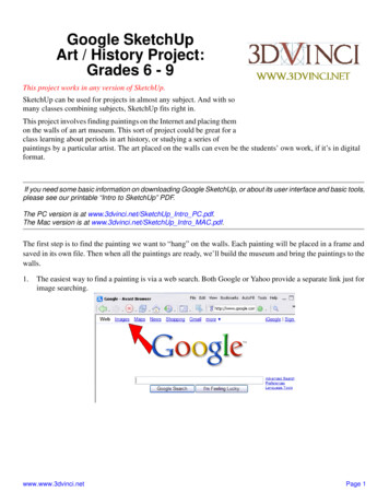
Modifying ObjectsOnce you have simple shapes in the scene, SketchUp includes multiple tools for modifying those shapes and curves. Some of these toolscan extrude the shape and others can divide and intersect thecurves to create new shapes. Learning to use these tools enables you to createunique models.IN THIS CHAPTERUsing the Push/Pull toolUsing the Follow Me toolUsing the Offset toolUsing the Push/Pull ToolThe Push/Pull tool is used to extrude the selected face. Extruding is the process of moving the shape in a perpendicular direction, adding faces at eachside. The result is to make a 2-D shape into a 3-D volume. The Push/Pulltool is selected from the Tools Push/Pull menu (P) or from the GettingStarted Toolbar.Creating 3-D objectsThe Push/Pull tool can only be used on face entities. Extruding a rectangularface creates a box object and extruding a circle creates a cylinder object. Touse the Push/Pull tool, simply select a face and drag it upward with the toolto add depth to the face, as shown for the hexagon in Figure 10.1.Dragging on a face with the Push/Pull tool increases the height that the faceis extruded. If you release the mouse button and then click and drag on thesame face again, you can continue to increase or decrease the extrusionheight. If you stop dragging with the Push/Pull tool and then double-click onthe face, the extrusion height is repeated again. For example, if you drag aface upward with the Push/Pull tool 1 foot and then release the mouse button and double-click on the face again, the extrusion height changes to183Defining intersections
Part IIIModeling Basics2 feet; if you double-click again, the extrusion height changes to 3 feet. This height extrusion canbe applied to any face that you double-click on.FIGURE 10.1Faces are extruded using the Push/Pull tool.Tutorial: Extruding faces of a columnUsing the Push/Pull tool, you can quickly extrude multiple faces to the same extent.To extrude all the faces of a column, follow these steps:1. With the Polygon tool, create a simple hexagon shape.2. Select the Push/Pull tool from the Getting Started toolbar. Drag upward on the hexagon face to extrude it into a column.3. Drag on one of the side faces to move it a short distance from the column center.4. Double-click on the adjacent face to extrude it the same distance as the first sideface.184
Modifying Objects5. Hold down the Alt key and drag with the scroll mouse button to rotate the view soyou can see the next adjacent side face and double-click on it.6. Continue to double-click on all the side faces around the column.Figure 10.2 shows the resulting column with equally extruded side faces.FIGURE 10.2By double-clicking on each side face, you can extrude each an equal amount.Creating holesNot only can the Push/Pull tool be used to extrude faces, but if you push in on a face that isalready part of a 3-D volume, the face is removed from the volume, and if you push it far enough,it creates a hole through the 3-D object, as shown in Figure 10.3. This provides a great way to create doors and windows in walls.If you hold down the Ctrl key while pushing or pulling a face, the top row of specified edgesremains, allowing you to create another extrusion level. If you don’t hold down the Ctrl key, theprevious extrusion continues without a break. Figure 10.4 shows multiple levels of the top faceafter extruding with the Ctrl key held down.18510
Part IIIModeling BasicsFIGURE 10.3Hole pushed through an extruded faceFIGURE 10.4Holding down the Ctrl key while extruding creates different levels.186
Modifying ObjectsThe amount of the extruded distance is displayed in the Measurements Toolbar. If you type a newvalue, the extrusion height changes to this new value.Using the Follow Me ToolThe Follow Me tool is used to make a cross-sectional area follow the length of a path that is positioned perpendicular to the shape. This is called lofting in other packages. The Follow Me tool isfound in the Tools Follow Me menu and also in the Edit Toolbar.To use the Follow Me tool, you need to create a face entity to be the cross-section area and a paththat the face follows. The face entity should be approximately perpendicular to the path. Withthese two items created, choose the Follow Me tool and click on the face to loft along the path. Youcan then drag along the path to follow. The path turns red as the shape is extruded. When theFollow Me tool comes to a corner, you can continue around the corner and the cross-section continues to follow the path, as shown in Figure 10.5.FIGURE 10.5The Follow Me tool can follow the edge of a shape like this rectangle.18710
Part IIIModeling BasicsFollowing the exact path can be tricky if you have a lot of detail, but you can make sure to get theexact path if you select the path with the Select tool prior to selecting the Follow Me tool. If theFollow Me tool detects a selected set of edges, it automatically applies the Follow Me tool to theselected edges.Following a pathAnother way to use the Follow Me tool is to have a cross-section face follow the length of an opencurve. This is useful for creating longer curved surfaces that follow a specific path like the trunk ofa tree or a bending straw.The easiest way to make sure that the path is perpendicular is to draw the face in aspecific view like the Top view and the path in a perpendicular view like the Frontview. These views are selected by choosing Camera Standard Views.TIPTutorial: Creating a sink drain pipeThe Follow Me tool can be used to create all sorts of pipes, even if they follow a strange path. Asink drain pipe follows a unique path to create a trap with two bends. It’s also a perfect chance topractice using the Follow Me tool.To create a sink drain pipe, follow these steps:1. Choose Camera Standard Views Front to switch to the Front view.2. Select the Line tool and draw a straight line from the base upward. Use the Arc toolto create two half circles that are opposite of each other, and conclude the path withanother straight line.3. Choose Camera Standard Views Top to switch to the Top view.4. Use the Circle tool to create a small circle that is perpendicular to the top of thepath.5. Choose Camera Standard Views Iso to switch back to the Isometric view.6. With the Select tool, click on all the segments that make up the path. Select theFollow Me tool and click on the top circle face.Figure 10.6 shows the resulting pipe.188
Modifying ObjectsFIGURE 10.6The Follow Me tool can make a cross-section follow an odd path.Beveling an edgeThe Follow Me tool can also be used to add a bevel to the edge of an object. The bevel profile canbe cut into the existing face. The face can then be selected normally with the Follow Me tool andthe edge selected as a path. Figure 10.7 shows a long extruded rectangle turned into a uniquebookshelf by drawing some connected arcs on the end of the object and using the Follow Me toolto bevel the lower edge.18910
Part IIIModeling BasicsFIGURE 10.7The Follow Me tool can bevel object edges.Lathing about a circleIf you construct the cross-section path to be the interior of an object and then make the path asimple circle, you can use the Follow Me tool to lathe 3-D objects. Figure 10.8 shows a baseballbat created by drawing the outline of the bat’s interior and then using the Follow Me tool to followthe shape about a circular path.Although SketchUp doesn’t have a spherical primitive object, you can quickly create a sphere by using the Follow Me tool on two circles of equal size that are oriented 90 degrees to each other.TIP190
Modifying ObjectsFIGURE 10.8The Follow Me tool can also be used to lathe circular objects.Using the Offset ToolOne of the easiest ways to create a room of four walls is to draw a rectangle and then subtract awayan inset rectangle that is only smaller by the thickness of the intended walls. If you manually createa rectangle and try to exactly match the drawn rectangle, one of the walls may be thicker if youdon’t exactly match the outer rectangle. An easier way to match the outer rectangle is with theOffset tool. The Offset tool (F) is found by choosing Tools Offset and in the Getting Started andEdit toolbars.To use the Offset tool, simply click on the face or curve that you want to offset and drag to set thedistance from the original. When you release the mouse, a new copy of the original face is created.You can also type a specific distance value in the Measurements Toolbar.19110
Part IIIModeling BasicsIf an offset distance is set by dragging, you can duplicate the offset distance again by doubleclicking on the new face. The target in Figure 10.9 was created by dragging to create the first offsetring and then double-clicking within the interior face to create more offsets.FIGURE 10.9The Offset tool creates faces that are inset or outset from the original.The Offset tool can also be used to clone and offset lines and curves. It can only be used on two ormore selected co-planar lines. To offset a selection of lines, simply select them and then click anddrag on the selected lines. Figure 10.10 shows a set of zigzag lines that are duplicated using theOffset tool.192
Modifying ObjectsFIGURE 10.10The Offset tool can also offset selected lines.Detecting IntersectionsWhen two 3-D objects overlap, SketchUp continues to recognize them as whole objects, making itso you cannot select and remove specific parts. For example, in Figure 10.11, portions of thesphere and the cube’s surfaces are overlapping, but in the leftmost instance, selecting any part ofthe sphere selects the entire sphere. This makes it difficult to work with the intersecting pieces.You can have SketchUp identify and mark the intersecting lines by cho
of SketchUp 7 Pro, as well as your own free copy of Google SketchUp 7. You'll also find most of the 3D models from the book, so you can follow the tutorials and gain hands-on practice in the techniques. System Requirements: See the CD appendix for details and complete system requirements.