Transcription
3D Massing Graphics Using Sketchup and Photoshop1
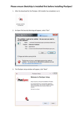
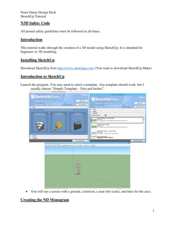
Download the City of Toronto Context Massing ModelThis document shows you how to generate a finished rendering usingTrimble’s Sketchu p Pro and Adobe Photoshop. You can find the entire Cityof Toronto 3D Context Massing Model posted on Open Data at:www.toronto.ca/openIn addition to Sketchup, other CAD and GIS file formats are available for youto use to create your model. Use this guide convert your model to Sketchupfor the final rendering.Sketchup and DWG files can be accessed using the interactive tile map.Note: Property Boundaries are not contained in the Massing Model files butare available for download from Open Data as Shape Files or by contactingToronto Maps for CAD files at www.toronto.ca/torontomapsUsing the Sketchup Massing Model FilesOpen the Sketchup file that contains the context area that surrounds the siteof your proposed development.Check to see that the units for your model is set to metres.Choose: Window/Model Info/Decimal/Metres1
Define Edge StyleIn order to keep the model as clean as possible it is recommended that youuse the most simple Edge Style available in Sketchup. You can do this bydeselecting “Profiles” in Sketchup’s Edge Style dialogue box.Choose: Views/Edge Style and deselect ProfilesChoose Perspective View For Your CameraFor achieve the appearance of a real world scenario set your camera to“Perspective”.Choose: Camera/Perspective2
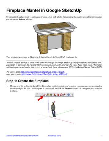
Import Your Proposed Building Into It’s ContextImport/paste your building into the Massing Model and locate it on your site.The proposed building(s) must be to scale and accurately located on thesite.Create a new layer and import your building into that layer. Also you canmove it to that layer after it is in place by selecting it and moving it to a newlayer using the Entity Info Palette.Highlight Your Application ModelSelect the Paint Bucket tool and in the Materials dialogue box choose Colorsin the pull down menu and select the colour swatch named Color 007.If your building model is grouped, double click the model to work insidethe group before selecting the Paint Bucket tool. If there are several groupswithin groups, keep double clicking until you have access to all surfaces.Select all faces and use the Paint Bucket tool to paint them orange.Alternatively you could “Explode” the grouped model, fill all faces orange andthen regroup the model if there are too many groups within groups.3
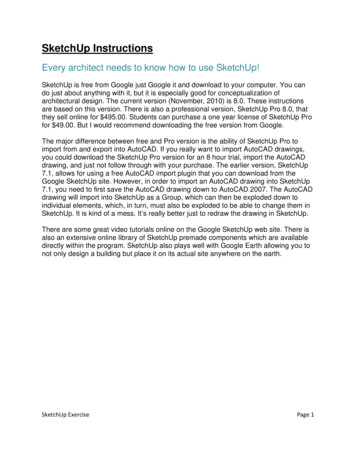
Sketchup Colour Palette for 3D Massing Model in ContextSubject SiteOrangeMassingsGreyCurbsLight GreyRoadsGreyParksGreenWaterBlueColour Swatches and RGB Valuesassigned the correct colours for each shape and have the same namingconvention for their layers. If you are using models generated using othersoftware, you can use this guide to colour your shapes.4
Confirm your Building HeightSelect the Tape Measure tool and click at a point where your building meetsthe ground, then slide the Tape Measure tool up to the top of your building.As you hover at the top of the building the measurement will be shown forthe distance to that point from the starting point. Confirm that your buildingis to scale and make note of the height - you will need it to calculate thedistance and height of the camera when establishing a viewpoint.Refer to your Elevation Drawings to confirm your building heights.Establishing a ViewpointNote: For help establishing a viewpoint using your building height or widthrefer to Appendix 1: Establishing a Viewpoint.Once you have established the viewing distance in metres from your building,use the Tape Measure tool to create a guide with an end point set to theestablished distance from the building on the ground. To do this, click theTape Measure tool at a point where the building meets the ground and thenmove your cursor along the surface of the ground, type in the measureddistance and hit enter to create the guide point.If you create an new Layer and place the guide on that new layer you can turnoff the layer and hide the guide when you export your final rendering.5
Positioning the CameraSelect the Position Camera tool and click on the guide point that you justcreated in the previous step.Establishing the Height of your CameraNotice that when you clicked on the Guide Point with the Position Cameratool, the tool changed to the Look Around tool. All you need to do now issimply type the desired height and hit enter and the camera’s Eye Height willbe moved vertically to the exact height you typed.You can now click and pivot the camera around a stationary point in the airto find the best view of your subject site.6
Moving the Guide Point to Reposition the CameraIf for some reason you are not satisfied with the view you established in theprevious step and want to move the camera to create a more suitable view,you can do this by rotating the guide. Using the Select tool, select the guide(it will highlight once selected) and then choose the Rotate tool.With the Rotate tool click on the origin point of the guide where it meets theground at the base of the building. Before you click you will notice that theRotate tool is either green, red, black or blue - you will want it to be bluewhich will allow you to rotate horizontally along the surface of the ground.After your first click at the origin of the guide make a second click at the endGuide Point and move your mouse until you rotate the end Guide Point to anew location. By rotating the guide in this fashion you maintain the correctdistance from the building.Once you have established a new location for the Guide Point, position yourcamera following Steps 9 & 10.Creating a SceneHaving gone through all of this work to generate a view you don’t want toloose it if you change the file in any way. The best way to save this view isby creating a Scene. A Scene will save all the details including views, layerseffects and so on. To save a Scene you will use the Scene Palette.Choose: Window and select Scenes.- In the Scene Palette click the Plus Button to create a scene.- You can rename the scene once you have created it.7
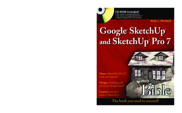
Adding FogAdding Fog will give the impression of reality and make the backgroundslowly fade into the distance.Choose: Window and select Fog- In the Fog Palette use similar setting as shown here.- Update your scene in the Scenes palette to save the Fog settings.Export the Scene For Final Rendering in PhotoshopChoose: File/Export/2D Graphic8
Save the Image as a JPEG FileIn the Export Dialogue box select JPEG Image (*.jpg) and use the settingsshown here.Finishing the Rendering Using Adobe PhotoshopOpen the JPEG image you just created in Photoshop.9
Setting the ResolutionOpen the Image Size dialogue box.Choose: Image/Image Size.In the Image Size dialogue box make sure the Re-sample Image option isDeselected. Check to make sure that Constrain Proportions is selected andChange the Resolution to 200 Pixels/Inch. Click OK to close the Image Sizedialogue box.Your image is now the correct size and resolution. Your next step will be tocrop it to a square.Setting your Crop Tool to a SquareSelect the Crop Tool.In the Crop Tool Options dialogue box choose 1 x 1 (Square).10
Cropping the Image to a SquareYour view should look something similar to this - with a Square Crop.Center your Development Proposal to the Middle of the Square Crop. Makesure that you Do Not Crop the Height. Simply just center the orange buildingin the middle and hit Enter to crop the image.Select the SkyNow that you have a square image, select the Magic Wand tool and check tosee that you have a Fairly Small Tolerance Setting. Click the Magic Wandtool somewhere in the white area where the sky is to be painted blue.11
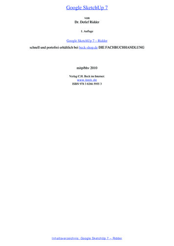
Selecting the Sky Blue ColourClick on the Set Foreground Colour button to bring up the Colour Pickerdialogue box. You can use either Pantone 657C from the Colour Library orsimply select the RGB values 204-214-235.Painting the Sky Gradient BlueSelect the Gradient tool and the setting Foreground (Blue) to Transparent.Click and drag the Gradient tool from the top of the image straight downuntil you reach an area where the buildings start. A blue gradient will bepainted in the selection area as shown here.12
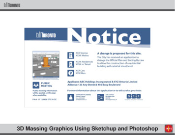
Save your Finished RenderingDeselect the sky selection and Save your file.Import Final Rendering into Sign Master Template and LabelOpen the Development Application Sign Master in Adobe Illustrator andplace your final rendering in the Illustration Area as shown. Label theStreets, Rotate the North Arrow to show where north would be in the image,Specify the Direction and Add the Date that the image was generated or thedate the application was filed. If you are updating an existing sign use thedate the rendering was updated.A shortcut to linking your new rendering in Illustrator. Select the existingimage in the template and go to your Links Palette and Relink to the file youjust created. The old image will disappear and your new rendering will bepositioned in it’s place.13
In addition to Sketchup, other CAD and GIS file formats are available for you . to use to create your model. Use this guide convert your model to Sketchup for the final rendering. Sketchup and DWG files can be accessed using the interactive tile map. Note: Property Boundaries. are not contained in the Massing Model files but