Transcription
INTEGRATING PHOTOGRAMMETRIC TECHNOLOGIESAND GEODETIC METHODS FOR 3D MODELINGGeorgeta PopFaculty of Geodesy, Geodesy and Photogrammetry Department, Technical University of Civil Engineering Bucharest,124 Lacul Tei Boulevard, Bucharest 020396, Romania –(p.georgeta)@yahoo.comCommission V, WG V/3KEY WORDS: Photogrammetry, Terrestrial, Civil Engineering, Building model, Close RangeABSTRACT:The main aspects of digital photogrammetry and its applications in the architectural field are illustrated in this paper. Here are alsodescribed the advantages of using modern surveying equipment in architectural photogrammetry. Practical aspects are exemplifiedusing the 3D model of two buildings from TU Delft University: “Aula” and “Faculty of Aerospace Engineering”. In addition, theaspects of collecting data using a total station, a terrestrial laser scanner and a digital non-metric photo camera are analyzed, as wellas the adjustment of this information using AutoCAD, Leica Cyclone, Google SketchUp and Google Earth. A great number of usersrequire an increasingly precise 3D buildings model. Applications can be found in the field of Geographic Information Systems (GIS),for urbanism and city planning, for flooding simulations, for microclimate investigations, for tourism offices, for police and militaryactivities, in telecommunications for signal propagation analyses, for landscaping, etc. This significant demand for 3D city models isleading to efforts greater than before, in developing 3D building reconstruction methods intended to minimize the costs for the 3Durban modelling. At the present time, the research is going towards an automated reconstruction and production of fast results.development of close range photogrammetry since the 1960s.From the many areas of application of close rangephotogrammetry, this field has become one of the bestestablished and most well known. At the same time, it hasperhaps not been so glamorous or as original as some otherareas of application. Nevertheless, the field is much changedfrom the early years of development. In the close rangeapplications as in the whole photogrammetric methodology, theintroduction of computers has very much changed the ways inwhich the technique works and is applied. From the computingpoint of view, we can observe that due to the rapiddevelopments in both the software and hardware areas, practicalvisualizations are feasible, at the moment, even for complexobjects and areas covering large 3D datasets. In the past,photogrammetric multi-image systems were used together withenlarged analogue images placed on digitizing tablets. Two ormore overlapping photographs taken from different angles wereusually handled with those kinds of systems. Currently,software applications may processes image data based ondigital and analogue imaging sources such us pictures fromsemi-metric or non-metric cameras.1. INTRODUCTION1.1 General considerationsFrequently, the 3D models are used for visualization in order togenerate “reality-like” scenes and animations. Speaking fromthe IT industry point of view, we can observe that due to thefast developments in both the software and hardware fields, atthe present time, practical visualizations are possible even forcomposite objects and for large areas covering a vast number of3D datasets. The main process typically results in acombination of real world data and computer generated datawith the purpose of adding value and information to a 3D modelin such a way that it becomes usable for various types ofanalyses and interrogations.The information used in this type of projects may havenumerous sources: 3D laser scanning, total stations, digitalPhotogrammetry, laser altimetry, maps - all of them incombination with data generated from other various disciplines– related to the project’s purpose. From the point of view of 3Ddata gathering techniques, the latest technology developmentsare showing noticeably improvements, in both resolution andaccuracy for all the techniques: aerial and close rangePhotogrammetry, airborne or terrestrial-based laser scanning,mobile mapping and GPS surveying.2. HARDWARE2.1 GPT 7003i-Topcon total stationThe versatile GPT 7003i total station from Topcon’s GPT-7000series gives us up to 250 m reflectorless range measurementsand up to 3000 m with a prism. Dual optical EDM design itmaintains focused beam accuracy and allows us to measureonly the target we select even at long distances. Captured sitephotos are incorporated into the measurement data tosuperimpose design points or stakeout points.There are a variety of approaches with diverse resolutions,accuracies, methods, completion times, stages and costs. I willtake a look in this paper at one approach towards 3D modellingof buildings and information collection using combined datafrom digital Photogrammetry, mobile mapping, laser scanning,conventional surveying and cartography-based reconstruction.The development of architectural and archaeologicalphotogrammetry has been very much a part of the whole549
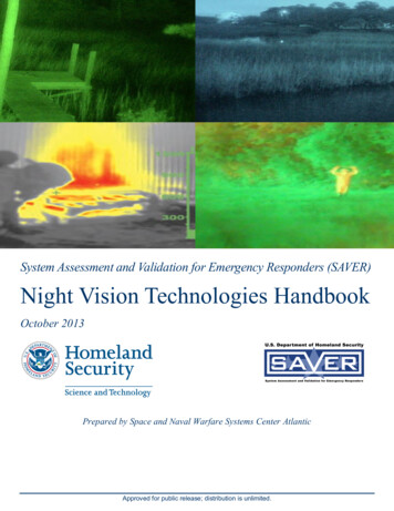
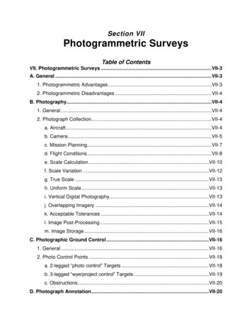
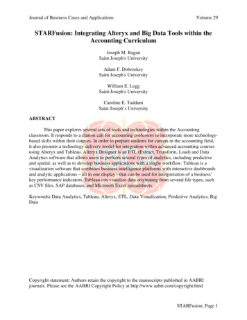
The International Archives of the Photogrammetry, Remote Sensing and Spatial Information Sciences. Vol. XXXVII. Part B5. Beijing 20084. 3D MODELLING2.2 Canon EOS 350DThe specifications of the Canon EOS 350D camera are givenwith a sensor resolution of 8.0 Megapixels that matches animage size of 3456 x 2304 pixels, a three times optical zoomwith a focal length between 18-55 mm named in the technicaldescription of the manufacturer.4.1 Modelling data from Total StationThe study was made using the 3D model of the „Faculty ofAerospace Engineering” building from Technical University ofDelft’s campus (Netherlands). The measurements were takenwith a GPT 7003i-Topcon total station and processed with theTopcon Link software. Pictures of the surveyed points and sitewere made directly using the totals station but also with adigital non-metric camera Canon EOS 350D. Laser technologyinstead of infrared measurements was used for acquiring thepoints with a 5mm precision and the 3D model was realizedwith AutoCAD 2007 software. More than 400 points have beenmeasured and calculated for the 3D model. These points wereexported from Topcon Link as .dxf files and then imported intoAutoCAD.2.3 FARO LS880The FARO LS880 laser scanner has a maximum vertical fieldof view of 320 with an angular resolution of 0.009 . In thehorizontal direction the field of view is 360 with a resolutionof 0.00076 . The scanner operates in the near infrared spectrumat a wavelength of 785nm. The maximum scanning speed is120.000 3D measurements per second. In our project we usedmeasurements with lower angular resolutions of 1/5 or 1/4 ofthe maximum resolution.The 3D model was generated based on surfaces and solids frommeasured points using AutoCAD 2007. This 3D model wasimported in Google SketchUp were we able to define thetexture and with help at this software knowledge I exported the3D model in Google Earth. Figures 1-7 illustrate the resultingmodel in different representations and from different views.3. SOFTWARE3.1 AutoCAD 2007Made by Autodesk, this is a software application widely usedfor 3D modelling. The same CAD principles of 3D architecturalmodelling apply to any object from toasters to the “Taj Mahal”building. For example, the 3D model in AutoCAD can begenerated using surfaces and solids. Creating 3D objects is a loteasier than before, because the process is more interactive andthere's more visual feedback as you work. You just drag acrossto create the base and drag up (or down) to create the height. Oryou can enter exact measurements. Other solid commands usethe same interactive process and you can use complex solidslike the pyramid and the helix.3.2 Google SketchUpSketchUp is a 3D software application used to create everythingfrom 3D massing models to fully rendered and highly detailedmodels. SketchUp is used predominately on the front-end of thedesign process where designs are in a fluid and tentative state.Figure 1. Measured points3.3 FARO SceneMade by FARO Technologies, Inc. – this is a modern tool,mainly used for controlling the scanner and registering the pointcloud data. The registration process can be done either withnatural targets (like corners) or with the help of spherical targets.Further more, it is also possible to set the scanning parameterslike horizontal and vertical angle resolution.3.4 Leica CycloneThe inherent completeness of 3D point clouds represents one oftheir major advantages over other sources of geometricinformation. Cyclone’s unique Object Database Client/Serversoftware architecture provides the highest performanceenvironment for laser scanning projects. Cyclone softwaremakes it easy for users to manage data efficiently in databases.Everyone can work concurrently on the point databases, therebyreducing the need to copy and/or transmit large point cloudproject files.Figure 2. Surfaces and solids550
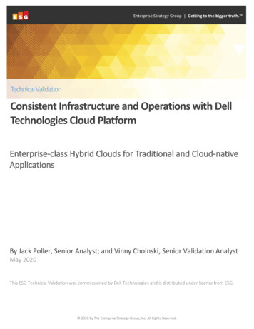
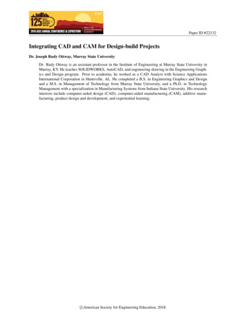
The International Archives of the Photogrammetry, Remote Sensing and Spatial Information Sciences. Vol. XXXVII. Part B5. Beijing 2008Figure 3. 3D model of building – from lines and points inGoogle SketchUpFigure 6. The 3D model of Aerospace Faculty from TU Delft inGoogle SketchUpFigure 4. 3D model of building - with texture in GoogleSketchUp – lateral viewFigure 7. 3D model import from Google SketchUp to GoogleEarth – lateral view4.2 Scanning principlesThe FARO scanner uses a visible „eye safe” laser to scan athigh speed. A grid of points is produced based on a userdefined spacing over the chosen area, thus creating a 3D „PointCloud” of the site, up to 360o and at distances of maximum 76m from the scanner. In this respect, the scanner is like a camerawhich records the detail that can be seen at each location. As inphotogrammetry, control points are required to link the variousscans together in order to create a continuous model. This isdone by placing targets within the scanning area and eithersurveying their locations or scanning the same control pointsfrom other locations.The scanner is attached to a laptop that runs the FARO Recordsoftware, allowing the data to be viewed and manipulated onsite. The data captured by the scanner forms a dense cloud of3D points classified by colour or hue based on the intensity ofthe returned signal. This helps to give the cloud depth andtexture, in order to enhance the interpretation of the details fromthe cloud.Figure 5. 3D model of building - with texture in GoogleSketchUp – frontal view551
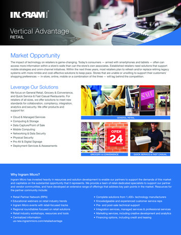
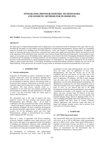
The International Archives of the Photogrammetry, Remote Sensing and Spatial Information Sciences. Vol. XXXVII. Part B5. Beijing 2008The exterior of the building was scanned using the FARO LS800 terrestrial laser scanner and each “points cloud” wasimported in the FARO Scene software. The scans were viewedin real time on the laptop computer and checked - beforemoving on to the next location - to ensure that the area had beenfully captured.4.3 Site operationsThe study was made using the 3D model of the „AULAconference centre” building from Technical University ofDelft’s campus (Netherlands).In this case, using a somewhat different approach than in thefirst case, I wanted to realize the registration of the buildingusing the measurements obtained with FARO LS880 laserscanner imported into the LEICA Cyclone software.The exterior of the building “Aula” - the conference centre was scanned in two days using 20 scans of the building from 20locations, with each scan taking no longer than 20 minutes. Thisincreased the number of scans and scanning locations thatwould normally have been required, as it was essential toachieve a good coverage of points throughout the scanned areas.From FARO Scene software each “points cloud” was exportedlike a pts file in order to allow the registration with the LEICACyclone software. For the registration of the building weimported pairs of scans – two by two – (for ex. Scans 001 and002), choosing 6 common points (corners of windows orspherical targets) for each pair of “points cloud”. If the modelmet the precision requirements ( 2mm), we than added the next“points cloud” (Scan 003), based on the common pointsbetween 002 and 003 scans. Using the LEICA Cyclonesoftware, I have applied different filters (for example:luminescence) and on the same phase I erased the points thatwere not necessary for building modelling.The results of the case study are shown in Figures10-13:Figure 8. Aula – the conference centre4.4 Working with „points cloud”Within the scanner software, the „point cloud” can be viewedfrom any location where snapshots can be taken as additionalvisual aids. This information can be used as cloud data or as ameshed surface to give a photo-realistic image over thesurveyed site.Figure 10. „Cloud points” in CycloneFigure 11. The registration of two scans in CycloneFigure 9. „Points Cloud” for building’s facade552
The International Archives of the Photogrammetry, Remote Sensing and Spatial Information Sciences. Vol. XXXVII. Part B5. Beijing 20085.2.2 Disadvantages:Registration without spherical targets requires muchmore time and, on the same time, is not efficientenough to use only natural targets, because the controlpoints are not always superimposing the naturaldetails (like building corners, for e.g.).The software applications currently on the market arecomplex and sometimes not to easy to learn andmanage.Due to the large number of data – million of points fora single scan – the overall information is hard anddifficult to handle and requires dedicated hardwareand software applications.Considering this, we may conclude that total station and thelaser scanning are not competitive but rather complementarymethods. The selection of the measurement method(reconstruction system) depends on many factors: budget,application, object shape, processing time. A second problem isthe varying measurement accuracy due to different remissionproperties of the scanned surfaces. Different researching studiesare currently addressing these.Figure12. The result of registration for two scans in CycloneThe greatest advantage in using of the 3D models is thepossibility to extract virtually any information we want. Forexample: we can determine surfaces and volumes, makesections or flatten views of the object. As it is easy to observefrom my case study, the use of non-metric photos had alsooffered some advantages: less time in acquiring the images,high precision and wide covering of the model.REFERENCESAtkinson, K.B., 2001. Close Range Photogrammetry andMachine Vision, Edited by Atkinson, K.B., formerly ofDepartment of Geomatic Engineering University CollegeLondon.Figure13. The result of registration for whole building inCycloneFARO Scene User Manual – Copyright 2005 by FAROTechnologies, IncKasser, M. and Egels, Y., 2002. Digital photogrammetry,Taylor and Francis, London and New York.5. CONCLUSIONS5.1 Total Station5.1.1 Advantages:Easy to use topographic equipments and techniques.Standard modelling software, like AutoCAD or 3dsMax , can be used to generate the model from thesurveyed points.5.1.2 Disadvantages:Surveying with topographic equipments andtechniques it is time consuming especially during themeasurements phase.Manea (Pop) G., Bucksch A., Gorte B., 2007. 3D buildingsmodelling based on a combination of techniques andmethodologies. CIPA, XI International Symposium:AntiCIPAting the future of the cultural past”, Athens, Greece,1-6 October, Com.V, pg. 607-611.Miller, A.G., 1984. Application of Modern PhotogrammetricEquipment in Architectural Photogrammetry. InternationalArchives of Photogrammetry and Remote Sensing, XXV (A5)pg. 515-527.Patias, P., 2001. Visualization issues in photogrammetry,Proceedings of the 3rd International Image Sensing Seminar onNew Developments in Digital Photogrammetry, Gifu, Japan,Sept. 24-27, pg. 4-6.5.2 Laser scanning5.2.1 Advantages:Fast acquisition of a huge amount of 3D data in ashort period of time (125,000 points/second), makingthe laser scanning probably the most efficient methodfor data acquisition.Good metric accuracy - depending of what instrumentwe use, it can be of a few millimetres in precision.http://www.autodesk.com (accessed 2007)http://www.leica-geosystems.com (accessed 2007)553
The International Archives of the Photogrammetry, Remote Sensing and Spatial Information Sciences. Vol. XXXVII. Part B5. Beijing 2008554
Google SketchUp . SketchUp is a 3D software application used to create everything from 3D massing models to fully rendered and highly detailed models. SketchUp is used predominately on the front-end of the design process where designs are in a fluid and tentative state. 3.3. FARO Scene . Made by FARO Technologies, Inc. - this is a modern tool,