Transcription
Stray light control and analysis for an off-axisthree-mirror anastigmat telescopeLionel Clermonta,* and Ludovic AballeabaUniversité de Liège, STAR Institute, Centre Spatial de Liège, Liège, BelgiumbOIP Sensor Systems, Oudenaarde, BelgiumAbstract. Off-axis three-mirror anastigmat (TMA) telescopes provide excellent correction ofaberrations over a large field-of-view in one direction. In a push broom configuration, this lightweight and compact optical configuration enables high-performing imaging. Moreover, passivemulti-spectral acquisition can be achieved using a filter stack positioned at the detector vicinity.Stray light is a typical limiting factor for instrument performance and its control is specific to thetype of optical configuration. We describe the stray light control and analysis methods in an offaxis TMA. The design intends to control first-order scattering from non-optical surfaces and toblock straight shots. This is achieved through usage of elements such as apertures and baffles,both internal and external to the instrument. It will be demonstrated that the aperture stop is acritical element, whose stray light contribution can be controlled with V-groove vanes. Impact ofmirrors roughness, a manufacturing physical limitation, is evaluated by modeling the bidirectional scattering distribution function and computing the stray light distribution at the detectorfor point-like source illumination. We show that the scattering on the different mirrors broadendifferently the spot size, as the successive mirrors focus or expand the scattered rays differently.Finally, the ghost reflections inside the filter stack are evaluated and we show that there is nocross-talk between the different channels. 2021 Society of Photo-Optical Instrumentation Engineers(SPIE) [DOI: 10.1117/1.OE.60.5.055106]Keywords: stray light; three-mirror anastigmat; ghost reflection; scattering; ray tracing.Paper 20201114SS received Sep. 20, 2020; accepted for publication May 12, 2021; publishedonline May 28, 2021.1 IntroductionAn off-axis three-mirror anastigmat (TMA) is a type of telescope consisting of three curvedmirrors arranged in an off-axis configuration.1 They enable an excellent correction of aberrationswhile being obscuration-free.1,2 Compact and lightweight TMAs are particularly interesting forEarth observation applications where space segment dimensions is becoming a constrain. Whilethe field-of-view (FOV) along the off-axis is limited, TMAs are optimized with a large FOV inthe perpendicular direction.1–3 In a push broom configuration, the large FOV scans the Earth inthe across-track (ACT) direction. Along-track (ALT), the instrument looks at the same area of theEarth with a very small temporal shift. A detector with a stack of stripe spectral filters can beplaced at the focal plane (FPA) to enable passive multi-spectral observation of the Earth. In thatcase, there is only a small temporal shift between the spectral bands. With the progresses ofdiamond turning technology, high-performance TMAs can now be built to provide wide coverage for Earth observation on smaller and lighter platforms than traditional on-axis refractivetelescopes.4,5 For the future of Earth observation, TMAs are excellent candidates to fulfill a needfor compact high-performing instruments.In addition of aberrations correction, stray light is an important concern for optical instruments. Stray light designates any light that reaches the detector through a path or process different than the one intended by design.6 Its consequences can be the addition on the image ofunwanted signal and features as well as the broadening of the point spread function (PSF).Stray light can occur due to ghost reflections or scattering on either optical or non-optical*Address all correspondence to Lionel Clermont, lionel.clermont@uliege.be0091-3286/2021/ 28.00 2021 SPIEOptical Engineering055106-1May 2021 Vol. 60(5)
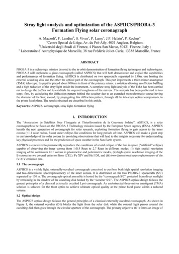
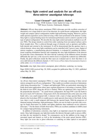
Clermont and Aballea: Stray light control and analysis for an off-axis three-mirror anastigmat telescopesurfaces. In the case of off-axis reflection systems, straight shots can create intense stray lightwhen rays are able to reach the detector without following the natural sequence of the opticalelements.7 This can be very damaging as their power is not attenuated by a ghost or scatteringevent. Earth observation is a domain where stray light requirements are often particularly tight.Moreover, it is usually harder to achieve such requirements on instruments with large FOV.While there is not a unique and universal recipe for stray light control, general best practicesare followed to ensure that the system has a sufficiently low stray light. This is done throughsmart opto-mechanical design and proper material selection, including black treatments.6,8 Forexample, stray light from non-optical surfaces is controlled by emphasizing on first-order scattering (i.e., light scattered only once before reaching the detector). These paths can be avoidedusing apertures, baffles, or vanes to prevent surfaces from being simultaneously illuminated andvisible from the detector.8 Straight shots can also be blocked with this kind of element or withhousing enclosure.7 Scattering from optical surfaces is minimized with clean and polishedsurfaces;6 however, there is obviously a physical limit. Regarding ghosts, these can be decreasedby proper orientation of the optical surfaces with respect to each other, using anti-reflection (AR)coatings on refractive elements or even by optimizing the lenses curvatures so that the ghosts areeither located outside of the photosensitive area or widespread at the detector,9 therefore presenting a smaller irradiance on each pixel. Stray light analysis is conducted to guide optomechanical design but also to predict and verify the design performances. For that purpose,an opto-mechanical model is built in a ray tracing software and the interactions with rays arecomputed to predict the stray light level at the detector.10,11 The typical approach is to ensureappropriate stray light performances at design level before initiating manufacturing. Indeed, correcting physically stray light on an already manufactured instrument is hard, if not impossible,and increases the complexity of calibration and stray light removal algorithms used for grounddata processing.In some kinds of design, for example, Cassegrain telescopes,6,8 the stray light control methods are well known and have been widely used. In this paper, we intend to describe the stray lightcontrol and analysis methods in the case of an off-axis TMA. Figure 1 shows the optical layout ofthe system considered here, where a global reference frame XYZ is defined. The system isdesigned by OIP Sensor Systems, which had also developed previously the ProbaV instrumentin a TMA configuration. It consists of three curved mirrors with the aperture stop on the secondary and an off-axis along YZ. The instrument is quasi-telecentric with an effective focallength (EFL) of 290.971 mm and root mean square (RMS) spot size between 2 and 6 μm.It has an FOV of about 7.2 deg in the ACT direction, aligned with the X axis. In theALT direction, along the Y axis, the spectral channels are contained within a full FOVof 2.4 deg.A fold mirror is placed after M3 to separate the spectral bands on two different FPAs. The advantage is that it allows to use two different types of detectors with potentially very differentFig. 1 Optical layout of an off-axis TMA. EFL ¼ 290.971 mm; full FOV 14.4 deg along X (ACT)and 2.4 deg along Y (ALT).Optical Engineering055106-2May 2021 Vol. 60(5)
Clermont and Aballea: Stray light control and analysis for an off-axis three-mirror anastigmat telescopeFig. 2 FOV for the transmission (T) and reflection (R) channels of the TMA.properties. The two FPAs are labeled T and R, respectively, for transmission and reflection channels. Each FPA has a 4-line sensor, in front of which is placed a butcher block. The butcher blockis a spectral filter window, which consists of an assembly of different spectral filters each composed of a stack of fused silica substrates with different dielectric coatings. The sensors have asemi-width of 39 mm and pixels of 13 μm. Table 3 gives the spot positions (x0 ; y0 ) and fields(f x ; f y ) for the center and edge of each channel. The spot position is given in a local referenceframe with the y axis aligned with the FPA spectral direction. The fields of the different channelsare considered with respect to the global reference frame and are also represented in Fig. 2.Equation (1) can be used to transform the fields in direction cosines with respect to the globalreference frame. Next, Table 3 gives the respective wavelength λ and filter transmission τfilter ofeach channel. In this exercise, the mirrors are assumed to have a transmission of 1; hence, thesystem transmission τ is the product of τfilter by the transmission of the butcher block’s ARcoatings. Finally, for an input beam of irradiance I input (expressed as W mm2 ) on plane XY,the power of the image-forming beam at detector is given by Eq. (2). In this equation,S ¼ 4766.8 mm2 is the area of the entrance pupil projected on plane XY, and θ is the fieldelevation. The elevation θ is between 0.797 deg and 7.290 deg therefore cosðθÞ 1, consequently the power expressed in W is Pdet I input 4766.8τ. On a detector with 13-μm pixelsand because the system has a sub-pixel spot size, a single field beam would thus give an irradiance of I input 2.81 107 τ W mm2 on the detector.81 C ¼ ��ffiffiffiffiffiffiffiffiffiffiffiffiffi1þtan2 ðf x Þþtan2 ðf y Þ;B ¼ C · tanðf y Þ :A ¼ C · tanðf x Þ(1)EQ-TARGET;temp:intralink-;e001;116;390Pdet ¼EQ-TARGET;temp:intralink-;e002;116;314I input · S· τ:cosðθÞ(2)This paper starts by describing how the TMA mechanical design is performed to controlstraight shots and first-order scattering from non-optical surfaces. Qualitative analysis is conducted by performing ray tracings at order zero (i.e., neglecting scatter or specular splits of rays)to verify if any objects is simultaneously illuminated and visible from the detector. The quantitative assessment of the stray light performance requires the identification of the paths foreseento be the most critical. This contrasts with the brute force approach where rays are traced andevery possible interaction in the system is computed. This would be both highly inefficient andhard to interpret. The paths identified are in particular the scattering on the aperture stop, thescattering on the mirrors, and the ghost reflections inside the butcher block. Each contributor isinvestigated separately by taking advantage of ray tracing software capabilities that allow settingthe ray trace properties differently on each surface of the design, therefore considering onlycertain interactions at a time. In this paper, the analysis is done with the FRED software.12This paper provides general guidelines for control and analysis of stray light in off-axisTMAs. An emphasis is put on design best practices and on the philosophy behind the analysis.This could serve as a recipe for the development of future instruments. The quantitative resultsextracted from these analyses will be used by the system engineer in the global instrument performance budget, which is out of the scope of this paper.Optical Engineering055106-3May 2021 Vol. 60(5)
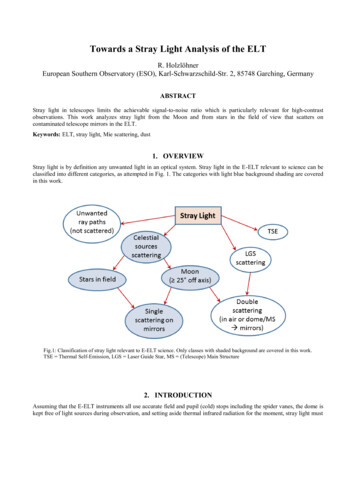
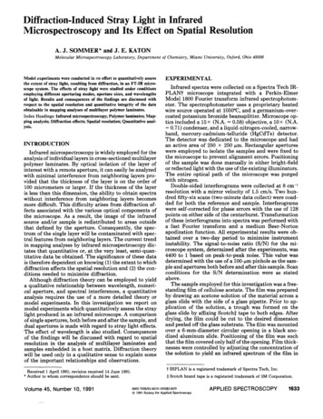
Clermont and Aballea: Stray light control and analysis for an off-axis three-mirror anastigmat telescope2 Mechanical Structure2.1 Principles and Qualitative AnalysisThe purpose of the mechanical structure is to hold the optical elements and to enclose the systemfrom the outside. It should not affect the image-forming beam (i.e., no vignetting) and it shouldbe optimized for stray light control. Usually, the mechanical surfaces are covered with a blacktreatment that absorbs most of the light and scatters the residual in all directions. The stray lightcontrol is performed by emphasizing on first-order scattering minimization. Scattering paths atsecond order (i.e., rays undergoing two scattering events) or higher are often neglected as theirpower are attenuated by the multiple scattering events. Therefore, we should focus on minimizing the number of surfaces that are simultaneously illuminated and seen from the detector asthese are the only ones producing first-order stray light.6 By definition, surfaces seen from thedetector are called critical surfaces.8 In a transmission on-axis systems, where rays are forced tofollow the natural sequence of elements, no surface located before the aperture stop is critical.8Hence, even if they are illuminated, they cannot produce first-order scattering. Similarly, nosurface located after the aperture stop is illuminated by in-field sources. However, it is possiblethat these surfaces are illuminated by out-of-field sources.8 Out-of-field illumination of surfacesafter the aperture stop can thus create stray light, which can be controlled by the appropriate useof baffles, apertures, or vanes.The case of an off-axis TMA is different. First, it is a system in reflection and therefore theaperture stop is simultaneously critical and illuminated.6 Second, the off-axis allows unwantedlight to propagate without following the natural sequence of elements. This offers the possibilityfor surfaces located before the aperture stop to be critical or for straight shots to occur. Figure 3shows a 3D view of the TMA opto-mechanical design, optimized for stray light control. It iscomposed of the following main elements: the housing, a front-baffle, an aperture labeled Π, anaperture stop covered with light traps, an FPA baffle, and a mount covered with vanes for the foldmirror. Hereafter, we describe the principles behind the different elements. Figure 4(a) shows theray tracing of the system with the central fields of channels R and T.A front baffle is placed at the entrance of the instrument. It has an input port through whichlight enters and an exit port in front of M1. Close to the exit port, the bottom surface of the baffleis opened so that the image-forming beam reflected on M1 can reach M2. The input and exitports enclose the image-forming beam envelope and are asymmetrical due to the shape of theFOV. The front baffle acts as a shield preventing out-of-field light from entering inside the instrument. The longer the baffle compared to its diameter, the more out-of-field light it blocks.Finally, vanes inside the baffle are used to block scattering on its surface. For example, theyFig. 3 3D view of the TMA opto-mechanical design.Optical Engineering055106-4May 2021 Vol. 60(5)
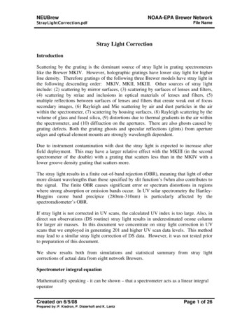
Clermont and Aballea: Stray light control and analysis for an off-axis three-mirror anastigmat telescopeFig. 4 (a) Ray tracing of central fields for channels R and T. (b) An out-of-field straight shot at (f x ;f y ) (0 deg; 9 deg) is blocked by the FPA baffle. (c) Out-of-field light at (f x ; f y ) (0 deg; 2 deg)blocked by internal vanes inside the FPA baffle. (d) Out-of-field light at (f x ; f y ) (0 deg; 5 deg)hitting the housing below M3.can be placed in a cold shield configuration,6,8,13 where no first-order scattering is able to reachthe exit port. Next, light reflected on M1 must pass through the aperture Π to enter inside thesystem. This aperture encloses the image-forming beam, blocks part of the unwanted lightreflected on M1 (similarly as a diaphragm in an on-axis system), and avoids direct light pathtoward M3. This includes out-of-field light but also light inside the FOV that is not part of theimage-forming beam. The closer the aperture Π is from the M2, the more unwanted light isblocked. The front baffle together with aperture Π is fundamental in blocking a large part ofuseless light outside of the system.The FPA baffle is a baffle placed close to the FPA (cf. Fig. 3), which restricts the direct viewfrom the sensors toward M3. As it hides the direct view toward aperture Π, it blocks the straightshot reflected on M1 toward the FPA, as shown in Fig. 4(b). With the FPA baffle, the only criticalsurfaces are the inside of the FPA baffle, the fold mirror mount, and the aperture stop. Vanes areused inside of the FPA baffle, as this one is illuminated by out-of-field sources located close tothe FOV [Fig 4(c)]. As the illumination is restricted within a small angular range, only a fewvanes are sufficient. Finally, the length of the FPA baffle is kept short to prevent its top surfacefrom being critical through reflection on M3, as this area is necessarily illuminated.Regarding the housing, the bottom surface below M3 is illuminated by out-of-field stray light[Fig 4(d)] but does not contribute to first-order stray light as it is not a critical area. If this area hadbeen critical, we could have removed that path by increasing the length of the front baffle.Another solution is overdimensioning M3 so that out-of-field light is specularly reflected towardthe FPA baffle, instead of scattered toward the sensor.At intermediary angles between the fields of channels R and T, light hits the top surface of thefold mirror mount. For channel T, stray light from this surface is avoided by covering it with Vgroove vanes, as shown in Fig. 5. Therefore, the stray light is limited to the very small area of theOptical Engineering055106-5May 2021 Vol. 60(5)
Clermont and Aballea: Stray light control and analysis for an off-axis three-mirror anastigmat telescopeFig. 5 Side view of the fold mirror mount.vanes edges. For channel R, a small part of the out-of-field light is able to reach the sides of themount around the fold mirror effective area. This is also a critical surface and thus the mirror canbe slightly overdimensioned to reflect specularly this light away from the sensor.The aperture stop, surrounding M2, is critical and illuminated by light from both inside andoutside of the FOV. Even with an excellent black treatment, a simple flat surface for the aperturestop would lead to a significant stray light. Consequently, a special design for the aperture stopwas implemented with V-grooves vanes as shown in Fig. 6(a). The principle of this design is thatthe top surfaces of the vanes are illuminated but are not seen from the detector; hence, they do notcreate first-order stray light paths. Analogously, the bottom surfaces of the vanes are seen fromthe detector but they are not illuminated [Fig 6(b)]. With this design, only the thin edges of thevanes are simultaneously illuminated and critical, thus contributing to first-order stray light.Here, V-groove vanes have rounded edges with thickness 60 μm.When designing the V-groove vanes, the angle of their top and bottom planes should beadjusted so that they are greater than the extreme rays angle on the aperture stop, when tracingrays, respectively, from the scene or from the detector. The optimal angle varies as a function ofthe height Y on the aperture stop; however, it is practical for manufacturing concerns to take theworst case (here, the angle between both sides is 29 deg). While some margin can be taken on theangle, it should not be too much acute as this increases the total number of vanes, thereforeincreasing the combined area of the edges.In our case, a multi-level system of V-groove vanes is used. This is because the vanes couldnot be placed at the same height as the mirror. Consequently, side surfaces between the differentlevels are simultaneously critical and illuminated. Yet, we will show that they have a small contribution due to small view factor and because the path involves weak backscattering. Finally, asmall ring between the aperture stop and the mirror is also critical and illuminated.Fig. 6 (a) Light trap configuration at the aperture stop, made of V-groove vanes on three levels.(b) The top surfaces of the V-groove vanes are illuminated but not critical, whereas the bottomsurfaces are critical but not illuminated.Optical Engineering055106-6May 2021 Vol. 60(5)
Clermont and Aballea: Stray light control and analysis for an off-axis three-mirror anastigmat telescopeIn summary, the opto-mechanical design of the TMA blocks straight shots and provides straylight control for first-order scattering from every contributor except two. The two exceptions consist of some small components on the aperture stop and the edges of the vanes on the fold mirrormount. This was verified by comparing the surfaces on which rays fall when performing a forwardand backward ray tracing with interactions only at zeroth order. The next step is to decide what typeof black treatment to apply on the different components. Currently, several black coatings withexcellent bidirectional scattering distribution function (BSDF) performances are available on themarket. Among them, Acktar black magic,14 commonly used in the space industry, is selected forthe aperture stop as it can contribute to first-order stray light, with a large quantity of light illuminating it. Surfaces in close proximity with the sensors are also recovered with Acktar (fold mirrormount and FPA baffle). All other components of the design, where first-order scattering is controlled, are recovered with black anodization, which have worse performances than Acktar butpresent the advantage to be more affordable. The next step is to perform a quantitative analysisto evaluate the impact of the first-order scattering paths. The impact of the vanes edges at the foldmirror mount is neglected as they have a small exposed area, a small quantity of light falling onthem, and an excellent black treatment. In the case of the aperture stop, the quantitative analysis isperformed at first order as well as at second order as a large quantity of light falls on it.2.2 Aperture Stop Quantitative AnalysisA quantitative analysis is performed to evaluate the impact of scattering on the aperture stop. Forthat, the point source transmittance (PST) is computed as a function of the field. Defined byEq. (3), the PST corresponds to the stray light irradiance (I FPA ) when the instrument is illuminated with a collimated beam of unit irradiance8 (I input ). The PST is computed for the reflectionand transmission FPAs. The irradiance is measured on an analysis surface placed right in front ofthe butcher block and covering the different spectral channels. Hence, for each FPA, we getPST τ, which can be multiplied by the system transmission τ (cf. Table 1) to get the stray lightTable 1 Properties of the different spectral channels at center and edge of the line sensors.Channel #T1T2T3T4R1R2R3R4x 0 (mm)y 0 (mm)f x (deg)f y (deg)θ (deg)λ 1.1907.2900 0.720.0001.0591.0595900.500.4939 0.727.1921.0597.2680 1.440.0000.9280.9285620.500.4939 1.447.1900.9287.2480 2.160.0000.7970.7976550.500.4939 2.167.1880.7967.231000.000 0.8170.8178650.970.963907.162 0.8167.20700.720.000 0.9470.9475900.500.49390.727.160 0.9467.22101.440.000 1.0771.0774430.970.95391.447.158 1.0767.23602.160.000 1.2061.2065900.500.49392.167.155 1.2067.254Optical Engineering055106-7May 2021 Vol. 60(5)
Clermont and Aballea: Stray light control and analysis for an off-axis three-mirror anastigmat telescopeFig. 7 BSDF of Acktar black magic14 as a function of the scatter angle θs , for different incidenceangles θ0 . The TIS at normal incidence is 0.93%.on a given spectral channel. Figure 7 shows the BSDF of Acktar black magic, applied on theaperture stop and used for PST computation. The curves correspond to the average BSDF overthe spectral range of the instrument.14 While the BSDF angular profile can vary slightly with thewavelength, its total integrated scattering (TIS) stays around 1%. Here, the TIS is 0.93% atnormal incidence and a scaling of the PST could be performed to evaluate the impact of a different TIS,PST ¼EQ-TARGET;temp:intralink-;e003;116;417I FPA:I input(3)Stray light is evaluated at first- and second-order scattering. First-order scattering concernsonly the edges of the vanes, as well as the sides 1, 2, and 3 as labeled in Fig. 6(a). Importancesampling is used to trace only scattered rays directed toward mirror M3, which limits the raytracing time by avoiding tracing useless rays.10,11 Because the edges of the vanes and sides surfaces are critical directly and not through reflection on M2, it is not necessary to trace scatteredrays toward M2. Indeed, light scattered toward the mirror M2 would not end up at the FPA. Thesecond-order scattering, however, is ray-traced separately by allowing rays to be traced in alldirections from any surface on the aperture stop. Figure 8 shows the PST as a function of the fieldðf x ; f y Þ, when combining results at first and second orders. As it shows, stray light from theaperture stop occurs mainly for fields inside the instrument FOV. When the field is varied, thefootprint of the rays hitting the aperture stop is displaced and gets vignetted for out-of-fieldsources. Hence, the PST presents some variation inside the FOV and progressively drops to zerooutside of the FOV when light is completely blocked by the front baffle or by aperture Π. Aneven faster reduction of the out-of-field PST could be achieved by increasing the length for thefront baffle.Figure 9 shows the profile of the PST as a function of f x , for f y ¼ 0. It shows first order,second order, and the decomposition of different paths from first order. As it shows, second orderis small compared to first order, with a proportion between 10% and 17% of the total stray light.About half of first-order stray light comes from scattering on the edges of the vanes. Hencereducing the thickness of the edges would have a significant impact on the aperture stop straylight, nevertheless it should not be so thin that the black treatment does not adhere. The secondcontributor to first-order scattering is the ring around M2. Its edges also contribute for a smallpart of the stray light. Despite the relatively large area of side 1, it has a small view factor and isilluminated at razing incidence; hence, it gives a small backscattering stray light. The view factorfor sides 2 and 3 is even smaller, hence they account for a negligible proportion of the stray lightand are thus not represented on the graph.Optical Engineering055106-8May 2021 Vol. 60(5)
Clermont and Aballea: Stray light control and analysis for an off-axis three-mirror anastigmat telescopeFig. 8 PST for first- and second-order scattering on the pupil stop as a function of the field, for(a) reflection and (b) transmission channels.Fig. 9 Aperture stop PST τ as a function of f x , for f y ¼ 0, decomposed between order 2 scatteringand the different paths at order 1.3 Scattering from the Mirrors3.1 Bidirectional Scattering Distribution FunctionThe mirrors of the TMA are manufactured by diamond turning followed by polishing and thelimitations of the process create roughness on their surfaces. Consequently, light reflected on amirror is partly scattered away from the specular direction, therefore broadening the PSF.6 We areinterested in estimating how the scattering on each mirror broadens the nominal spot.The surface roughness was verified on a flat sample, manufactured with the same process asthe TMA mirrors. Figure 10 shows its roughness topology at three different positions, obtainedby white light interferometry with zoom 40 . The mean and RMS roughness are given inTable 2; polishing steps were performed until RMS roughness was below 1 nm. To simulatethe effect on the instrument, it is important then to derive the BSDF of the as built mirrors.Optical Engineering055106-9May 2021 Vol. 60(5)
Clermont and Aballea: Stray light control and analysis for an off-axis three-mirror anastigmat telescopeFig. 10 Topology map of the mirror measured at different positions of the sample with white lightinterferometry (zoom 40 ).Table 2 Statistics of the mirror roughness for the topology measurements of Fig 10.Measurement #Mean roughness (nm)RMS roughness (nm)a0.5340.652b0.8050.999c0.4490.575While it is theoretically possible to derive the BSDF from topology measurements,6,15 this iscomplex and model validity is uncertain. Instead, BSDF measurements were directly performedat the facility of ESTEC (European Space Research and Technology Center, ESA), where asample is illuminated at an incident angle θ0 and the scattered light is measured as a functionof the scatter angle θs , inside the plane defined by the normal and the incident light.Measurements were performed at 633 nm for different incidence angles. The signature of theBSDF setup was measured as well, it presents a significant signal up to about 0.045 deg fromspecular. Above that angle, the signature is negligible compared to the BSDF measured for thesample. Data contained within 0.045 deg from specular were thus removed from the BSDFmeasurements. Figure 11(a) shows the resulting BSDF curve, with as expected a peak centeredon the specular direction and a rapid decrease away from that angle.A rough optical surface can be modeled with a Harvey model,16 whose profile is given byEq. (4) and depends on three parameters (b, s, and L). The BDSF is traditionally plotted as aFig. 11 (a) Experimental BSDF at 633 nm measured at different incidence angles.(b) Experimental BSDF on a double log scale, with data close to the specular direction removed,and compared to a double Harvey model fit (fit#1 from Table 3).Optical Engineering055106-10May 2021 Vol. 60(5)
Clermont and Aballea: Stray light control and analysis for an off-axis three-mirror anastigmat telescopefunction of j sin θs sin θ0 j on a double logarithmic scale,6,15 emphasizing two distinct regimes:a flat top at the origin and a linearly decreasing behavior at angles further away from specular.Parameter b corresponds to the amplitude of the flat top, s is the slope of the linear regime, and Lgives the transition position between the two regimes.6 In practice, Fig. 11(b) shows that theexperimental data present two linearly decreasing regimes with different slope
Stray light is a typical limiting factor for instrument performance and its control is specificto the type of optical configuration. We describe the stray light control and analysis methods in an off-axis TMA. The design intends to control first-order scatteri