Transcription
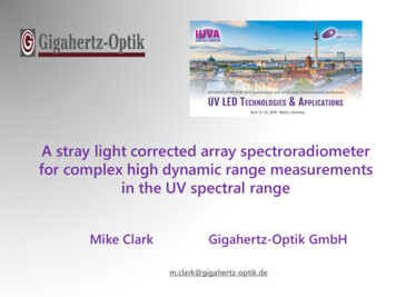
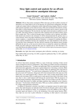
Stray Light Analysis of a Mobile Phone CameraJordan JurCollege of Optical Sciences, University of Arizona, Tucson, AZ 85721Master’s Project spring 2016ABSTRACTStray light, defined as unwanted light or energy [1], is an unintended consequence which degrades thedesigned functional performance of an optical system. For optical imaging systems, the designedfunctional performance is quantified by the diffraction based image quality metric of MTF. Traditionaloptical design software’s, like ZEMAX, only correct for aberrations influenced by the first order systemparameters, such as, f-number and field of view [2]. However, optical analysis software’s, like FRED,consider the effects which coatings and mechanical structure have on image quality. These parametersare known as stray light sources and are divided into specular and scatter components. Here wedemonstrate that well-established mitigation strategies, specific to specular and scatter mechanisms,can be utilized to minimize stray light. The results indicate that specular contributions can be mitigatedwith improved AR coatings, the scatter contributions can be mitigated with cleanliness control andstructure material selection while a cylindrical lens barrel design over a conical one improves bothcontributors.I. INTRODUCTIONDue to the evolution of the mobile phone market over the past decade consumers have come to expectmore from the designers and manufacturers of their mobile devices. When cameras were firstintroduced to the mobile phone platform expectations were low due to the unfamiliarity of such afeature on a mobile device. As cameras became a prevalent feature on the mobile phone, consumerexpectations rose which promoted a new realm of competition within the market. As the competitionincreased, so did the complexity of the performance related challenges for the design andmanufacturability of the mobile phone camera. Fast forward to present day and we see that one ofthese major performance related challenges is stray light mitigation; the topic of this project11.Stray light is unwanted scattered or specular light or energy at the detector of an optical system, whichis not intended in the optical design. In essence, stray light will degrade the MTF and resolution of themobile phone camera and must be minimized. The sources and mechanisms of stray light have beenstudied since the 1950’s and mitigation strategies have been well developed for some of the lesscomplex entities. This project will examine and measure the specular and scatter contributors to straylight within a FRED optical model and employ some of the common mitigation methods to minimizestray light. An example of one type of specular stray light contributor, known as a ghost image, can beviewed in figure 1. This picture was taken with an iPhone 6 camera.1Given the vast array of stray light sources, the mitigation techniques discussed in the following sections will only consider nominal designvalues and neglect perturbations inherent to the manufacturing process. For an accurate stray light analysis of a manufactured optical system,these manufacturing perturbations should be considered. See “Molded Optics: Design and manufacture by Michael Schaub for moreinformation.JUR 1
Figure 1. Stray Light Ghost Images in iPhone6 CameraII. STRAY LIGHT FUNDAMENTALSIn order to properly and effectively execute a stray light design, the sources and sensitivities of straylight must be well understood. This section will introduce the main sources of stray light common toimaging systems. In addition, the sensitivity to which the first order properties, geometry and materialsof the iPhone 6 camera impact the stray light performance will be explored. Any environmental effectson the stray light performance will be ignored for this analysis.Stray light behaves in sequential and non-sequential manners which follows the behavior of light asobserved in nature. As a result, different modeling methods will need to be executed in order tomeasure the different contributions. A list of stray light sources common to imaging systems [3],divided into specular and scatter categories, are listed in table 1. Note that only the stray lightmechanisms with a medium or high sensitivity will be considered for this project.Mechanism TypeSPECULARSCATTERMechanismSurface ReflectionsDetector ReflectionsStructure ReflectionsModeling MethodNon-sequential RaytracingNon-sequential RaytracingNon-sequential RaytracingSurface Micro-roughnessBSDF w/ First-Order N.S. RaytracingStructure ScatterBSDF w/ First-Order N.S. RaytracingParticle ContaminationBSDF w/ First-Order N.S. RaytracingMaterial Bulk ScatterBSDF w/ First-Order N.S. RaytracingStress BirefringenceBSDF w/ First-Order N.S. RaytracingFluorescenceBSDF w/ First-Order N.S. RaytracingTable 1. Stray Light iumHighLowLowLowUnderstanding the specific variables which impact the magnitude of the specular and scatter stray lightmechanisms will aid the mitigation strategy.JUR 2
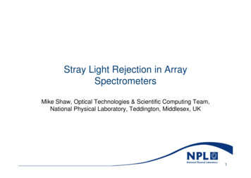
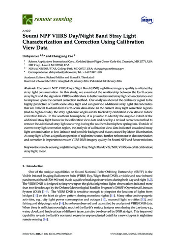
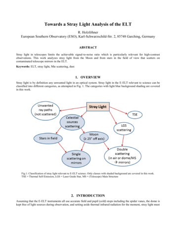
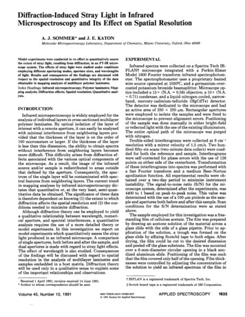
SPECULAR MECHANISM (GHOST PATHS)Unlike the random nature of scattered rays, ghost rays are deterministic according to the law ofreflection, law of refraction, and the grating equation. Due to their deterministic nature, anything whichaffects these laws is a considered as a variable which impacts the mitigation of the specular stray lightcontributions. Note that there are no diffractive optics used in this optical system therefore variableswhich impact the grating equation will not be explored.It is common practice to coat the optics with an AR coating to minimize reflections within an opticalsystem. Less surface reflection means that more light will be either absorbed or transmitted by theoptic. The absorption of VIS light by plastic optics is very low therefore it can be inferred that lessreflection generally implies more light is transmitted. By changing the transmission of a coated surfacethe specular stray light mechanisms can be controlled. Bare uncoated surfaces will have a Fresnelreflection and transmission components of 4% and 96%, respectively2. Plastic optics generally have poorperforming coatings compared to glass optics but can still achieve AR coatings of 98% [4], [5].In addition to altering the surface coating properties, optic edges may be baffled by some means.Plastic optics are commonly designed with flanges on their edges which act as mounting interfaces toopto-mechanic barrels [6]. These flanges not only aid in the mounting of the optic but also serve toreduce the number of sneak paths within the optical system. A baffle may block a direct line of sightfrom the universe to the detector, as shown in figure 2.Figure 2. Opto-Mechanic BaffleLastly, the power (sag) of an optic surface should be minimized as to prevent a ray from being totallyinternally reflected. Once a ray TIRs off on surface it has the potential to TIR off another. In the case ofplastic molded optics, the flange area provides a secluded set of surfaces which may contribute to TIRevents and increase the specular stray light contributions. This mitigation technique is common practicefor aberration control of the lens design and is known as lens bending or lens splitting [7]. In summary,specular stray light mechanisms can be controlled by altering the coating properties, adding baffles,and/or altering the optical design to minimize the power of a surface and the potential for a TIR event.2Assuming optic index of refraction is 1.5.JUR 3
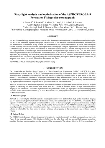
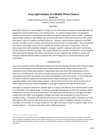
Figure 3. TIR EventSCATTER MECHANISMSDue to the nondeterministic nature of scatter light the analysis is a bit more complex. On themacroscopic scale, scattered light is light which cannot be described by the law of reflection, law ofrefraction, or the grating equation. The figure below illustrates scatter from a flat surface [8]. Note thatthe largest ray represents the specular reflection component whereas the smaller rays represent thescattered components.Figure 4. ScatterThe magnitude, distribution and direction of scattered light by a given surface is described by thebidirectional scatter distribution function (BSDF). In radiometric terms, the BSDF can be thought of asthe ratio of the outgoing radiance to the incident irradiance. Therefore, BSDF has units of inversesteradians.𝐵𝑆𝐷𝐹(𝜃𝑖 , 𝜙𝑖 , 𝜃𝑠 , 𝜙𝑠 ) 𝑑𝐿(𝜃𝑖 , 𝜙𝑖 , 𝜃𝑠 , 𝜙𝑠 )𝑑𝐸(𝜃𝑖 , 𝜑𝑖 )(1)where θi and φi are the angles of incidence and θS and φS are the angles of scatter in the threedimensional space described in Cartesian coordinates. When the BSDF is integrated over 2π steradiansthe contribution of the scattered light can be quantified; this is known as the total integrated scatter orTIS. BSDF impacts the TIS of a surface which has a dependence on the surface roughness, wavelength,JUR 4
and index of refraction of that specific surface. A more detailed, quantitative description of TIS and itsimpact on BSDF will be discussed in detail in section VI. A summary of the stray light mechanisms andtheir variables are listed in table 2 [3].CategorySPECULARSCATTERMechanismSurface ReflectionsDetector ReflectionsStructure ReflectionsVariables/Mitigation StrategyOptical Design, AR Coatings, and/or BafflesOptical Design, AR Coatings, and/or BafflesOptical Design, AR Coatings, and/or BafflesSurface Micro-roughness Material, Optical Polish Selection and/or Edge BlackeningParticle ContaminationCleanliness ControlStructure ScatterOptical and/or Baffle DesignMaterial Bulk ScatterMaterial Selection and/or ProcessingStress BirefringenceMaterial Selection and/or Mounting FeaturesFluorescenceMaterials Selection and ProcessingTable 2. Summary of Stray Light Variables/Mitigation StrategyNow that the variables which impact the specular and scattered stray light contributions are understoodthese concepts can be applied to a particular camera system. As a rule of thumb pointed out byPfisterer, the following process should be executed when performing a stray light analysis [9].Step12345678TaskConstruct Optical ModelConstruct Mechanical ModelDetermine Critical ObjectsDetermine Illuminated ObjectsDetermine Common ObjectsConstruct Coatings and Scatter ModelsSetup Importance SamplingPerform Stray Light AnalysisTable 3. Stray Light Mitigation ProcessIII. OPTICAL MODELThe optical model analyzed for this report is the iPhone 6 camera. The lens prescription was uploadedto ZEMAX based on the information provided in the patent literature [10]. It is common practice to notprovide the exact lens prescription in the patent therefore a preliminary analysis of the optical systemmust be performed to ensure that decent performance is achievable from the prescription provided.The analysis will show that the information provided in the patent literature demonstrates decentperformance and no optimization of the design is necessary.The iPhone 6 camera consists of eight elements, including the aperture stop and detector, for a total of15 surfaces. The first order parameters of the system are listed in table 4 and the optical layout can beviewed in figure 5.JUR 5
ParameterValueFocal Length (mm)6.325Diameter of EP (mm)2.87f/#2.2FFOV ( ) 18No. Elements8WavelengthsVIS SpecTable 4. First Order ParametersFigure 5. Optical LayoutThe five lens are all 14th order aspheric surfaces (any surface which is not spherical) which is describedby the polynomial deformation of a conic in equation 2.𝑧(𝑟) 𝑟 2 𝑅 𝐴𝑟 4 𝐵𝑟 6 𝐶𝑟 8 𝐷𝑟10 𝐸𝑟12 𝐹𝑟14(2)21 1 (𝐾 1)(𝑟 𝑅)where r is the radius of curvature of the surface, R is the half diameter of the surface, K is the conicconstant of the surface, and A thru F are the aspheric coefficients. The exact values of these terms canbe view in the optical prescription provided in figure 6.Figure 6. Optical PrescriptionJUR 6
LENS FUNCTIONSEach lens in the camera is made from a specific material which has a funcion to control a certainaberration. The materials used in this optical system are list in table 5.ElementOuter WindowLens 1Lens 2Lens 3Lens 4Lens 5IR PSUGlassAluminumBrand Name Refractive Index, ndSapphire1.7715TOPAS 50131.5333Udel P-17001.634Udel P-17001.634TOPAS 50131.5333Udel P-17001.634N-BK71.5168iSightPBTTable 5. Camera Materials [11]The outer window is the first element in this optical system and has a function to protect the lenes fromthe outside environment. It is made of sapphire which is a very hard material that will providemaximum resistance to scratches and other possible abrasions. The next element, the first lens, islocated at the aperture stop, specifically, surface 1 of the first lens. Since this surface is located at theaperture stop it will only contribute to spehrical aberration [12]. In addition, this surface is the mostpowerful and as a results contributes the most spherical aberration to the system. Lenses 2 and 3 aremeniscus lenses which correct for spherical aberration. They are also made of a flint plastic which canbe used to correct for chromatic change in focus (LCA) and magnification (TCA) caused by the crownplastic of lens 1. Lens 4 surface 1 and lens 5 surface 2 are designed such that their radii of curvature forthe speherical component lie nearly coincident with the aperture stop. This is significant because thechief ray goes through the center of curvature of these two surfaces and they will not contribute to anyodd aberration which has a dependance on the chief ray height [13].Figure 7. Exploded ViewIn addition, the higher order aspheric terms of lenses 4 and 5 serve to correct for astigmatism by meansof flattening the field [7] and to limit the chief ray angle of incidence on the detector [14]. Controllingthe chief ray angle of incidence allows for the control of the illumination of the image and will segwayinto the more detailed analysis section.JUR 7
ANALYSISAs is expected from any patent literature, the optical prescription provided is not ideal and will need tobe analyzed. The relative illumination, known as irrandiance in radiometric terms, varies quartically withthe chief ray angle of incidence, according to equation 3.𝐸 𝐿𝐴cos 4 (𝜃)𝑑2(3)where L is the radiance of an extended source, A is the area of the source, d is the distance from thedetector to the extended source and θ is the angle of incidence of the chief ray on the detetor. Notethat the quotient is the solid angle of detector subtends from the point of view of the extended object.Generally speaking, it is good practice to limit chief ray angle of incidence such that the relativeillumination difference from the center of the optical axis to the edge of the image falls within the gainbandwidth of the detector. By doing so the detector can adequately compensate for the relativedifference in illumination. The angle of incidence can be approximated using first order parameters, asshown in equation 4.𝜃 arctan(ℎ′ /𝑓)(4)where h’ is the image height, found in figure 5, and f is the focal length of the optical system found intable 4. Equation 4 calculates the chief ray angle of incidence to be 17.14 which yields a theoreticalrelative illumination of 0.834. Using the “Relative Illumination” analysis function in ZEMAX, shown infigure 10, it is demonstrated that the relative illumination for this optical system is actually 0.521(roughly 1.6X worse) partially becaue there is some vignetting through the system.Figure 8. Image SimulationIgnoring the vignetting affects of the pupil mismatch seen at the edge of the picture, the effect of therelative illumination can be observed in ZEMAX using the “Extended Scene Analysis” tool. Note that theon-axis, center portion of the image remains the same in both images and the image quality degrades asthe image moves radially outward.In addition to the relative illumination, there are other metrics of the optical design which were notideal. Figures 9 thru 12 show many metrics commonly used to interpret the image quality. According toequation 5, the diffraction limited performance of the camera should yield a spot diameter of 2.95μm atλ 0.55μm. Note that this is the radius of the beam which contains 83.8% of the beam energy.JUR 8
𝐷 2.44𝜆𝑓/#(5)For the prescription used for this analysis, the spot diameter which contains 83.8% of the beam is3.058μm (Figure 12); roughly 1.036X worse. Ignoring the performance differences from the idealdiffraction limited case, the optical model still achieves adequate performance so that a stray lightanalysis can be performed.Figure 9. OPD Fans and Wavefront MapFigure 10. MTF and Relative IlluminationJUR 9
Figure 11. PSF Cross Section and Linear PSF at Image Plane3rd ZERO2ndZERO1st ZEROFigure 12. Log PSF at Image Plane and Encircled EnergyIV. MECHANICAL MODELThe lens barrel was designed in SolidWorks from an exported *.STP file of the optical prescription. Thelens barrel, a variation of a monolithic clamshell, was designed using best known methods for plasticmold injected optics and is made of a readily available plastic-PBT. Best known methods were usedsince no literature regarding the mechanical barrel design was found. The extrema ray bundles, shownin figure 5, represent the FOV of the camera and were also exported in the *.STP file to ensure that thebarrel design did not unintentionally vignette any rays.It is common for plastic lenses to be made with flanges at the edges so that these features can be usedas mounting points in the lens barrel and also serve as datums for alignment. In SolidWorks, the flangeswere designed for each lens to allow a clearance of 10% of the lens surface clear aperture to reducehoop and contact stresses induce into the optic from this mount [6]. Once the lens barrel was designedaround the lenses, the lenses were deleted because SolidWorks is unable to recognize the 14th orderaspheric terms, rather, it uses a cubic spline feature recognition which poorly fits to an aspheric surface.The lenses were later imported to FRED.JUR 10
Figure 13. SolidWorks Assembled SystemBefore the CAD file was exported to FRED, it was discovered that an effective way to control the straylight contribution of each surface within the lens barrel is to segment the barrel into optical spaces [24].This method of segmentation is a useful trick when stray light mitigation is required, specifically, whenimportance sampling comes into play. Additionally, the understanding of how different optical spacescontribute to stray light can be looped back to the design and manufacturing processes so that amitigation strategy can be employed. The segmented lens barrels are shown in figure 14.Optical Space76543210Figure 14. SolidWorks (left) and FRED Segmented Lens BarrelJUR 11
V. CRITICAL, ILLUMINATED & COMMON OBJECTSCritical and illuminated objects are important features to recognize within an optical system becausethey identify which surfaces will contribute to first order stray light. By definition, a critical object is anyobject which the detector can see while looking towards the universe. Conversely, illuminated objectsare objects which the universe can see while looking towards the detector. Objects which are bothcritical and illuminated are known as common objects and potential first order stray light sources. Thisimplies that all surfaces of optical elements are common objects because, by design, they see bothcritical and illuminate objects.To determine the critical and illuminated objects, a non-sequential forward and reverse ray trace isperformed, respectively. The specific details of critical and illuminate objects recognition are below.Note that all scattering models were turned off to ensure that scattered rays were not contributing tothe identification of the critical and illuminated objects. In addition, all ray trace controls wereconfigured to only transmit the specular ray.CRITICAL OBJECTSTo determine these critical objects, a non-sequential reverse ray trace, starting just off the surface of thedetector, was performed in FRED. This involved placing a Lambertian source 0.001mm from the surfaceof the detector and tracing one million rays backwards through the system. In addition, all ray tracecontrols were configured to only transmit the specular ray. The exact details of the source are shown intable 6. Notice that the rays propagate at 45 because the source was place 5mm in front of theoptical system. If the source were to be placed the entrance pupil of the system then the rays wouldhave to propagate at 90 .Ray PositionSurfaceType NameRaysDirectionOffsetIterationReverse Ray Direction?Ray DirectionsImage PlaneType NameRandom SurfaceRays1,000,000Outer Semi-ApertureUse Dir. FunctionHole Inner Aperture-0.001mmSource TypeNoShapeYesForward DirectionLocal X DirectionTable 6. Critical Source ParametersRandom Directions into an range145 for X & Y0 for X & YLambertianCircular(0, 0, 1)(1, 0, 0)JUR 12
Ray 60.0059820.0066680.016599ElementLens 2Lens 3IR FilterLens 4Lens 4Lens 5SurfaceBevel 1Bevel 1EdgeEdgeBevel 2Bevel 2Aperture StopInner WallBarrelOptical Space 0: TrimSurf 22BarrelOptical Space 1: B-Spline Surface 4BarrelOptical Space 1: B-Spline Surface 5BarrelOptical Space 1: TrimSurf 31BarrelOptical Space 2: B-Spline Surface 3BarrelOptical Space 2: B-Spline Surface 22BarrelOptical Space 3: B-Spline Surface 2BarrelOptical Space 3: TrimSurf 12BarrelOptical Space 3: B-Spline Surface 31BarrelOptical Space 4: B-Spline Surface 2BarrelOptical Space 4: TrimSurf 12BarrelOptical Space 4: B-Spline Surface 31BarrelOptical Space 5: B-Spline Surface 2BarrelOptical Space 5: B-Spline Surface 4BarrelOptical Space 5: TrimSurf 12BarrelOptical Space 5: B-Spline Surface 13BarrelOptical Space 5: TrimSurf 30BarrelOptical Space 5: B-Spline Surface 31BarrelOptical Space 6: B-Spline Surface 3BarrelOptical Space 6: B-Spline Surface 22BarrelOptical Space 6: TrimSurf 30BarrelOptical Space 7: B-Spline Surface 2BarrelOptical Space 7: B-Spline Surface 3BarrelOptical Space 7: TrimSurf 21BarrelOptical Space 7: B-Spline Surface 22BarrelOptical Space 7: TrimSurf 30BarrelOptical Space 7: B-Spline Surface 31Table 7. Critical ObjectsILLUMINATED OBJECTSTo determine the illuminated objects, a non-sequential forward ray trace, starting from the objectplane, was performed in FRED. This involved placing a source at the object plane and tracing one millionrays forward through the system. The exact details of the source are shown in table 8. Notice that therays propagate at 20 and not 90 because when the source was placed at the detector any raysJUR 13
outside of 20 would vignette and not propagate through the optical system and would becomputationally inefficient.Ray PositionSurfaceType NameRaysDirectionOffsetIterationReverse Ray Direction?Ray 11E-061.70E-060.0012450.003748Ray DirectionsObject PlaneType NameRandom Directions into an rangeRandom SurfaceRays11,000,000Outer Semi-Aperture20 for X & YUse Dir. FunctionHole Inner Aperture0 for X & Y0.001mmSource TypeLambertianNoShapeCircularNoForward Direction(0, 0, 1)Local X Direction(1, 0, 0)Table 8. Illuminated Source ParametersElementLens 3Lens 3Lens 4Lens 5Aperture StopAperture el 1Bevel 2Bevel 2Back FaceInner WallOptical Space 0: B-Spline Surface 3Optical Space 0: B-Spline Surface 5Optical Space 0: TrimSurf 13Optical Space 0: B-Spline Surface 14Optical Space 0: TrimSurf 22Optical Space 0: TrimSurf 31Optical Space 0: B-Spline Surface 32Optical Space 1: B-Spline Surface 4Optical Space 1: B-Spline Surface 5Optical Space 1: TrimSurf 13Optical Space 1: TrimSurf 22Optical Space 2: B-Spline Surface 3Optical Space 2: TrimSurf 21Optical Space 2: B-Spline Surface 22Optical Space 3: B-Spline Surface 2Optical Space 3: TrimSurf 30Optical Space 3: B-Spline Surface 31Optical Space 4: B-Spline Surface 2Optical Space 4: B-Spline Surface 3Optical Space 4: B-Spline Surface 22Optical Space 4: TrimSurf 30Optical Space 4: B-Spline Surface 31JUR 14
Ray cal Space 5: B-Spline Surface 2BarrelOptical Space 5: TrimSurf 12BarrelOptical Space 5: B-Spline Surface 31BarrelOptical Space 6: B-Spline Surface 3BarrelOptical Space 6: TrimSurf 21BarrelOptical Space 6: B-Spline Surface 22BarrelOptical Space 7: B-Spline Surface 2BarrelOptical Space 7: TrimSurf 12BarrelOptical Space 7: TrimSurf 30BarrelOptical Space 7: B-Spline Surface 31Table 9. Illuminated ObjectsThe following table is a list of objects which are both illuminated and critical- common objects. Bydefault, all surfaces of the optics are common objects because the detector must look through them tosee the universe. However, FRED knows this and excludes these surfaces which is why they do notappear in the table below even though they are considered common objects. The next task is to applycoating and scatter models to these surfaces so that their contribution to stray light can be analyzed.ElementAperture StopLens 3Lens 4Lens relBarrelOptical SpaceSurface1Inner Wall4Bevel 15Bevel 26Bevel 20TrimSurf 221B-Spline Surface 41B-Spline Surface 51TrimSurf 312B-Spline Surface 32B-Spline Surface 223B-Spline Surface 23B-Spline Surface 314B-Spline Surface 24B-Spline Surface 315B-Spline Surface 25TrimSurf 125B-Spline Surface 316B-Spline Surface 36B-Spline Surface 227B-Spline Surface 27TrimSurf 307B-Spline Surface 31Table 10. Common ObjectsJUR 15
VI. COATING & SCATTER MODELSWith the common objects now known, coating and scatter models can be applied to these surfaces.Many of the coating specifications for the iPhone 6 camera are considered proprietary information andthus unknown. However, it is reasonable to assume that in place of the exact coating specifications,common industry coating specifications can be applied. The same holds true for the surface roughnessspecifications for both the optics and structure. The specific coating and scatter models will be coveredin the coming sections.COATING MODELSCoating models were applied to the window, lenses, filter, detector and structure. The exact coatingspecification for each optic is listed in table 11. For reference, these models were all built with 550nmas the reference wavelength.Element(s) AffectedCoating TypeCoating SpecificationsGlass Window/ IR FilterAR (thin film)99%T & 1% RPlastic LensesAR (thin film)98% T & 2% RDetectorAR (Al)80% T & 20% RStructureBare93% A & 7% RTable 11. Coating Model SpecsAccording to Baumer, AR coatings on plastic optics can achieve values of 0.25%R using a 12 quarterwave (QW) layer when applied with the AR-hard coating deposition process [4]. However, the numberof deposition layers is linearly proportional to the cost of the coating [5] which implies that thistechnique is rather costly therefore a more conservative 2% reflectivity value will be used for the plasticlenses. Additionally, coating technology for glass optics is much more mature, therefore, a 99%reflectivity coating was determined to be an easily achievable value for the window and IR filter [15].Figure 15. Plastic (left) and Glass (right) Optic CoatingsSchulz demonstrates that the reflectance of uncoated PMMA at normal incidence is roughly 7% acrossthe entire visible spectrum [16]; the other 93% is absorbed. These absorption and reflectance valueswere then used to build the structure coating model.JUR 16
Figure 16. Structure (left) and Detector (right) CoatingsThe iPhone6 camera sensor, known as the iSight, is a CMOS detector with 8 megapixels and 1.5μm pixelpitch which yields a 4.25 mm2 square array. The exact coating specifications for this sensor areunknown but common coating specifications for sensors were used [17]. To be on the ultraconservative side, a value less than the uncoated transmittance will be used for the sensor surface. Itwas assumed that a 20% reflectance would be a good ultra-conservative value.Figure 17. Sensor CoatingThe uncoated transmission spectra for PMMA, PC and COP plastics are listed in figure 18. Although, thelens barrel is made from the PBT polymer it has similar reflection properties of these three polymers andwill serve as the reference for the bare, uncoated, reflectance properties of the lens barrel material.JUR 17
Figure 18. Transmission Spectra of PlasticsNext, these coating properties were then used to build coating models for each element in FRED. Ascreenshot of this interface is shown in figure 19. The wavelength, reflectivity and transmission datawere the only variables used for this coating model.Figure 19. FRED Coating ModelSCATTER MODELSThe following scatter models were used to produce scattered rays in FRED. Note that the contaminationmechanism effects all lScatter MechanismScatter ModelSurface Micro-roughnessHarvey ShackSurface Micro-roughnessFlat Black Paint (4.5%R at NI)Surface ContaminationMIE w/MIL-1246C density functionTable 12. Scatter Model SpecsJUR 18
HARVEY-SHACK MODELThe Harvey-Shack model is useful for smooth surfaces. Therefore, in order for the Harvey-Shack modelto be valid, the optical elements must
Stray Light Analysis of a Mobile Phone Camera Jordan Jur College of Optical Sciences, University of Arizona, Tucson, AZ 85721 Master’s Project spring 2016 ABSTRACT Stray light, defined as unwanted light or energy [1], is an unintended consequence which degrades the designed functional