Transcription
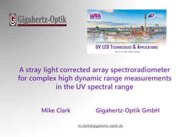
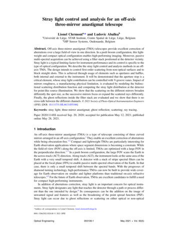
Stray light analysis and optimization of the ASPIICS/PROBA-3Formation Flying solar coronagraphA. Mazzolia, F. Landinib, S. Vivesc, P. Lamyc, J.P. Halaina, P. RochusaaCentre Spatial de Liège, Av. du Pré-Aily, 4031 Angleur, Belgium;bUniversità degli Studi di Firenze, 4 Piazza San Marco, 50121 Firenze, Italy ;cLaboratoire d’Astrophysique de Marseille, 38 rue Frédéric Joliot-Curie, 13388 Marseille, FranceABSTRACTPROBA-3 is a technology mission devoted to the in-orbit demonstration of formation flying techniques and technologies.PROBA-3 will implement a giant coronagraph (called ASPIICS) that will both demonstrate and exploit the capabilitiesand performances of formation flying. ASPIICS is distributed on two spacecrafts separated by 150m, one hosting theexternal occulting disk and the other the optical part of the coronagraph. This part implements a three-mirror-anastigmat(TMA) telescope. Its pupil is placed about 800mm in front of the primary mirror, a solution allowing an efficient bafflingand a high reduction of the stray light inside the instrument. A complete stray light analysis of the TMA has been carriedout to design the baffles and to establish the required roughness of the mirrors. The analysis has been performed in twosteps: first, by calculating the diffraction pattern behind the occulter due to an extended monochromatic source havingthe diameter of the Sun; second, by propagating this diffraction pattern, through all the telescope optical components, tothe prime focal plane. The results obtained are described in this article.Keywords: ASPIICS, coronagraph, stray light, formation flying1. INTRODUCTIONThe “Association de Satellites Pour l’Imagerie et l’Interférométrie de la Couronne Solaire”, ASPIICS, is a solarcoronagraph to be flown on the PROBA 3 Technology mission issued by the European Space Agency (ESA). ASPIICSheralds the next generation of coronagraph for solar research, exploiting formation flying to gain access to the innercorona ( 1.1 solar radius, Rsun) under eclipse-like conditions for long periods of time. ASPIICS will make a giant stepin our knowledge of the solar corona by providing observations that will lead to the insights necessary for understandingkey physical processes and for the prediction of space weather in the Sun-Earth system.ASPIICS is conceived to permanently reproduce the conditions of a total eclipse of the Sun in space ("artificial” eclipse)capable of observing the inner corona from 1.015 Rsun to 2.7 Rsun in different modes: (i) high spatial resolutionimaging of the continuum K F corona in photometric and polarimetric modes, (ii) high spatial resolution imaging of theE-corona in two coronal emission lines (CEL): Fe XIV and He I D3, and (iii) two-dimensional spectrophotometry of theFe XIV emission line.1.1 The coronagraphASPIICS is a visible light, externally-occulted coronagraph conceived to perform both high spatial resolution imagingand two-dimensional spectrophotometry of the inner corona. It is distributed on the two PROBA-3 spacecrafts (S/C)separated by 150 m. The coronagraph optical assembly is hosted by the “coronagraph S/C” protected from direct sunlightby remaining in the shadow of the occulting disk hosted by the “occulter S/C”. The ASPIICS optical design follows thegeneral principles of a classical externally occulted Lyot coronagraph. An unobstructed three-mirror anastigmat (TMA)solution is selected for the front optics to achieve ultimate optical quality at the prime focal plane within a reducedvolume.1.2 Optical designThe ASPIICS optical design follows the general principles of a classical externally occulted coronagraph. As shown inFigure 1, the external occulter (D1) blocks the light from the solar disk while the coronal light passes around theocculting disk then goes through the circular aperture of the coronagraph. The primary objective (O1) forms an image of
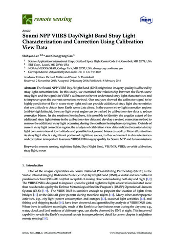
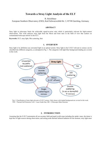
the external occulter onto the internal occulter (D2). The image of the surrounding bright fringe is blocked by slightlyover-sizing the internal occulter. The secondary objective (O2) re-images the entrance pupil (A1) onto the so-called“Lyot Stop” (A3) that blocks the light diffracted by the edges of the pupil. Finally, the corona image is formed by acamera (O3) onto the focal plane (F).Figure 1. Basic scheme of a classical externally occulted Lyot coronagraph.An unobstructed three-mirror anastigmat (TMA) solution is selected to achieve ultimate optical quality (then limitingover-occultation) within a reduced volume. The primary mirror is located 804 mm behind the entrance pupil. Theinternal occulter is located after the focal plane of the 3-mirror objective. This TMA is optimized for an object at infinityand the optical quality reached at the internal occulter allows very limited overoccultation and consequently highperformances. The additional optics after the internal occulter are not part of this analysis, the optical model is limited tothe design until the internal occulter (i.e. the "coronagraphic part"). The main reason to this limitation is the impossibilityto reduce stray light after the internal occulter due to the presence of the Fabry-Perot interferometer and theinaccessibility of the Lyot stop.Figure 2. Optical design for the ASPIICS Coronagraph.The analyses presented in this article have been performed in the framework of the ESA STARTIGER program whichtook place in the Laboratoire d’Astrophysique de Marseille (LAM) during a 6-month project between September 2009and March 2010. A TMA identical to the one proposed for ASPIICS has been built and used during the STARTIGERproject. Its top level specifications are presented in the following table.Table 1. STARTIGER TMA design top level specifications.STARTIGER TMA design top level specificationsEffective focal length800.417 mmEntrance pupil diameter100.8 mmMaximum field of view /- 0.8
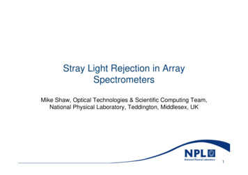
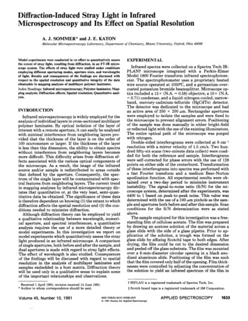
1.3 Objectives of the studyThe aim of this work was the evaluation of the stray light in the TMA from the external to the internal occulter (IO),including: a preliminary baffling design, the impact in term of stray light at the internal occulter level of the mechanical structure and the mirrors microroughness, the stray light coming from the diffraction by the external occulter (EO) (assumed to be a single, circular andthin disk), finally the definition of requirements on the surface properties of the external occulter’s rear face in terms ofspecular and diffuse reflection.The model was built in the ASAP ray tracing software. It contains the mirrors from the optical design as well as thestructure of the mechanical design.2. INTERNAL STRAY LIGHT ANALYSIS2.1 Baffles configurationThe first analysed source of stray light is the direct view between the entrance pupil of the TMA and the internalocculter. Here this direct view exists only through reflections on the TMA mirrors. To avoid this stray light, three baffleshave been placed inside the TMA. They can be seen in the Figure 3 and Figure 4 here below.Figure 3. Internal baffling of the TMA.
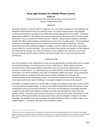
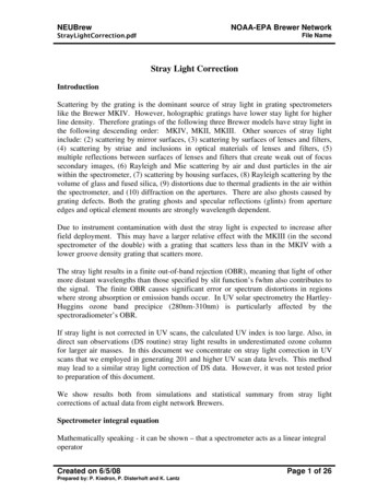
Figure 4. TMA model with internal baffles.To limit the stray light outside the field-of-view, a tube is used as an entrance baffle to the TMA. Nevertheless light canbe reflected or diffused inside this tube and then travel inside the TMA. Vanes are added inside the tube to prevent thisstray light. They are 7.5 mm high and separated by 32 mm (See upper part of Figure 5). These vanes avoid stray light toenter the TMA after one reflection inside the tube until an incidence angle of /- 24 which constitutes thus theunobstructed field of view (UFOV) of the TMA.The bottom part of Figure 5 presents vanes added to the structure wall near M1. They suppress a reflection or diffusionof light towards M1 which could propagate through the TMA mirrors until the internal occulter.10 mm50 mmFigure 5. Entrance baffle and vanes on the structure wall near M1.
2.2 Mirrors’ micro-roughnessDifferent micro-roughnesses have been applied to the 3 mirrors to check their impact in term of stray light level in theplane of the internal occulter. The roughnesses were introduced in the model as BRDF (bidirectional reflectancedistribution function) models using the Harvey-Shack mathematical model. An example is presented in Figure 6 for amicro-roughness of 1 nm.Figure 6. BRDF Harvey model curve for a roughness of 1 nm.Five roughnesses have been considered (0.2, 0.5, 1, 2 and 5 nm) and applied to each mirror one at a time. The stray lightlevel on the internal occulter plane for an unitary input flux has been computed for each case. The results are presented inTable 2 which shows also the TIS (Total integrated scatter) corresponding to each roughness. The important conclusionfrom this table is that all mirrors give a similar stray light level for the same roughness which indicates that no mirror isdominant in term of scattered stray light. From this table and the specification on the maximum acceptable stray lightlevel on the internal occulter, the maximum micro-roughnesses requirement of the mirrors can be easily fixed.Table 2. Stray light rejections on the internal occulter for different mirrors’ roughnesses for an unitary input flux.Roughness0.2 nm0.5 nm1 nm2 nm5 nmTIS2.2 10-51.4 10-45.6 10-42.2 10-31.4 10-2M16 10-61 10-44.2 10-41.7 10-31.2 10-2M27.2 10-68.3 10-53.3 10-41.3 10-37.5 10-3M37.4 10-61.1 10-44.4 10-41.8 10-31.3 10-23. DIFFRACTION FROM THE EXTERNAL OCCULTERTo simulate the diffraction by the external occulter of the light coming from the Sun two steps have been used. The firststep is to calculate the diffraction pattern behind the occulter (here at the entrance pupil of the coronagraph) and thesecond one is to propagate this pattern through the optical components of the coronagraph until the plane of the internalocculter. The diffraction pattern behind the occulter has been calculated analytically because it would require a too large
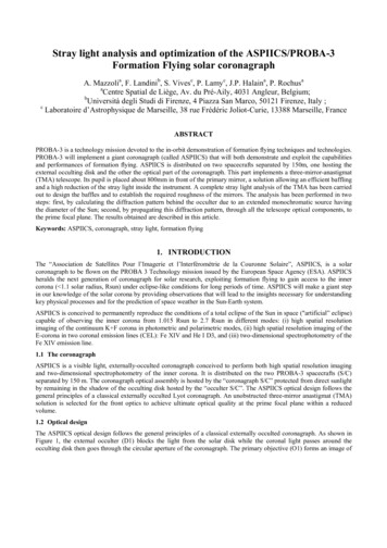
computation time in ASAP to reach enough accuracy. As the internal occulter’s function is to block the diffraction fromthe external occulter, the plane where this diffraction is analysed is the internal occulter plane.The calculation of the diffraction after the external occulter has been performed analytically for a small piece of theocculter’s edge (considered thus linear and with an infinite length in the direction perpendicular to the light propagation).An extended source with the size of the Sun has been considered. The diffraction pattern is computed in a section of theTMA entrance pupil. The obtained profile is presented in the Figure 7 below. The part of the profile corresponding to thepupil is limited by the dashed lines.To propagate the light from the Sun through the TMA after the diffraction by the occulter, the profile of the diffractionpattern inside the pupil is not sufficient. The pattern in the whole pupil plane is necessary. As a first approximation anddue to the large dimension of the occulter (1.5 m in diameter) with respect to the pupil diameter (100 mm) it has beenconsidered that the profile can be extended to the whole pupil. A view of the pattern in the whole pupil is presented inFigure 7.Figure 7. Profile of normalized energy distribution due to diffraction by the EXTERNAL OCCULTER in the TMA entrancepupil plane and the same diffraction pattern profile extended to the whole entrance pupilThe next step is the propagation of the previous pattern through the optical and mechanical model of the TMA built inthe ASAP raytracing software. To do this several points source are placed on the edge of the external occulter assumingan apodization of each beam with the diffraction pattern calculated above. The flux per source is equal to the flux in thediffraction pattern divided by the number of sources considered. The pattern in figure 7 corresponds to a linear edge onthe left of the pupil i.e. a point source placed on the edge in the negative part of the Y axis. Depending on the position ofthe source on the occulter’s edge, the apodization is rotated to take into account the position of the considered smalllinear edge with respect to the pupil position.As the internal occulter plane is the conjugate plane of the external occulter and due to the high distance between theexternal occulter and the coronagraph the imaging of the external occulter on the internal occulter plane is not a lotdegraded. As a consequence the spots are too small to be seen on a full image of the occulter. With a defocus on the focalplane, the ring surrounding the external occulter image becomes visible. The Figure 8 below presents the geometricalcomputation (i.e. without taking into account the diffraction for a better visualization of the ring) for several pointssource distributed on the occulter edge.
Figure 8. Geometrical image through the coronagraph of source points on the external occulter’s edge in a defocalized planewith respect to the internal occulter plane.To see more clearly the structure inside the ring on the internal occulter plane it is necessary to make a zoom on a smallpart of it. To do this several sources are placed close to each other on a small part of the occulter’s edge. Thevisualization window in the internal occulter plane is also chosen centered on the image with enough pixels to see thedetails of the diffraction pattern. An example is presented in the Figure 9 below. The width between the two first minimain the PSF-like profile on the right is 10 µm. The FWHM of this curve is around 4 µm.Figure 9. Image in the internal occulter plane (considering the diffraction) of source points located on a small part of theexternal occulter’s edge.4. REQUIREMENTS ON THE EXTERNAL OCCULTER’S REAR SIDE SURFACEPROPERTIESIn this last paragraph the effects of diffusion or reflection on the rear face of the external occulter are analysed. The wayto proceed was to place sources at the external occulter level and propagate the rays towards the TMA entrance pupil andthen through the TMA until the internal occulter. For the propagation inside the TMA the mirrors were considereddiffusive with a BRDF model corresponding to the RMS micro-roughnesses measured by the TMA manufacturer (1 nmfor M1, 0.4 nm for M2 and 0.3 nm for M3). The stray light rejection on the internal occulter was computed for eachmirror at a time. Different sizes as well as positions of the sources on the external occulter were used to see their impactin term of stray light level on the internal occulter.
The flux of the smallest source (1 mm²) is unitary and the fluxes of the other sources is 1 times the ratio between theirarea and the 1 mm² area. The stray light contribution for each mirror for different source areas centered on the externalocculter are presented in the following Table 3. From that table it can be seen that the stray light level on the internalocculter is proportional to the area of the emitting source on the external occulter.Table 3. Stray light rejections at internal occulter level for different source areas on the external occulter and diffusion onthe TMA mirrors.Source area1 mm²10 mm²100 mm²1 cm²10 cm²100 cm²1 m²Diffusion on fusion on ffusion on ncerning the effect of the source position on the external occulter, simulations have been performed for somepositions of the source. Displacements on only one axis or on both axes have been performed. The result is that theposition of the source has no effect on the stray light rejection since the values are similar to the one obtained for acentered source.From the coronagraph’s entrance pupil diameter (100 mm) and the distance between this one and the external occulter(150 m), the solid angle covered by the entrance pupil viewed from the external occulter is equal to 5.236E-2 str.Considering first the external occulter’s rear side as a Lambertian emitter it will diffuse the same amount of light in alldirections contained in an hemisphere (solid angle of 2π str) towards the coronagraph. The fraction of light entering theentrance pupil is thus equal to the ratio between these two solid angles i.e. 8.333E-3 times the total integrated scatter(TIS) of the external occulter’s rear side. From this last value, the Table 3 and the maximum level of stray light acceptedat the internal occulter level, specifications on the external occulter’s rear side surface properties in term of TIS isdetermined.5. CONCLUSIONSThe TMA of the future ASPIICS coronagraph to be flown on PROBA-3 has been optically and mechanically modelledfrom the external to the internal occulter. A first order baffling design to avoid direct stray light at the internal occulterlevel through reflections on the mirrors has been proposed. The impact of the mirrors’ micro-roughness in term of straylight on the internal occulter has been analysed for each mirror and for several micro-roughnesses. The diffraction fromthe external occulter has been simulated by propagating through the coronagraph optics the diffraction patternanalytically calculated at the entrance pupil considering the Sun as an extended source. Finally some requirements on theexternal occulter’s rear side surface properties have been determined.REFERENCES[1] Vives, S., Lamy, P., Levacher, P., Venet, M., Boit, J., L., "In-flight Validation of the Formation FlyingTechnologies using the ASPIICS/PROBA-3 giant coronagaph", Proc. SPIE 7010-3R, (2008).[2] Vives, S., Lamy, P., Venet, M., Levacher, P., Boit, J., L., "The giant, externally-occulted-coronagraph ASPIICSfor the PROBA-3 formation flying mission", Proc. SPIE 6689, (2007).[3] Evans, J., W., “A photometer for measurement of sky brightness near the sun”, J. Opt. Soc. Am. 38, 1038(1948).
2. INTERNAL STRAY LIGHT ANALYSIS 2.1 Baffles configuration The first analysed source of stray light is the direct view between the entrance pupil of the TMA and the internal occulter. Here this direct view exists only through reflections on the TMA mirrors. To avoid this st