Transcription
Advantech WebAccess Device Driver GuideModicon Modbus TCP/IPModbus TCP/IP/ Modicon EthernetDevice Driver GuideVersion 4.5 rev 0Advantech Corp., Ltd.page 1-1
Advantech WebAccess Device Driver GuideModicon Modbus TCP/IPTable of ContentsModbus TCP/IP / Modicon Ethernet Device Driver Guide1.Modbus TCP/IP Device n to Modbus Ethernet /TCPIP . 31.1.1Modbus Ethernet / TCP/IP . 31.1.2Ease of Use: Parameters . 41.1.3Redundant Comports . 41.1.4Modbus Protocols . 41.1.4.1 Modbus Ethernet / TCP/IP . 41.1.4.2 Modbus RTU. 51.1.4.3 Modbus ASCII. 5Configure Modicon / Modbus TCIP device . 5TCPIP Comport Properties . 71.3.1Comport Number . 71.3.2Description . 71.3.3Scan Time . 71.3.4Timeout . 81.3.5Retry Count . 91.3.6Auto Recover Time . 91.3.7Backup Port . 9Device Properties - Modicon . 111.4.1Device Name . 121.4.2Description . 131.4.3Unit Number . 131.4.4Device Type . 131.4.5Com Port . 131.4.6Unit Number . 131.4.7Device Address . 131.4.7.1 Multiple Devices with same Device Address . 14Configure a Tag . 14Step by Step Guide . 151.6.1Task 1: Configure a Communication Port . 161.6.2Task 2: Add Device (a PLC) . 181.6.3Task 3: Add an Analog Input Tag . 211.6.4Task 4: Add an Analog Output Tag . 241.6.5Task 5: Add a Discrete Output (also called Digital Output) . 281.6.6Task 6: Download changes to the SCADA Node . 311.6.7Task 7: Start the SCADA Node via Project Manager . 331.6.8Task 8: Start VIEW to verify communications to PLC . 351.6.9Task 9: Use Point Info (Tag Browser) to verify new tag . 371.6.10Task 10: Review the Port and Device List. 39Addendum . 421.7.1Device Failure . 421.7.2Troubleshooting an asterisk (*) . 421.7.3Use Station Status to diagnose problems . 43July 30, 2005Version 4.5 rev 0Advantech Corp., Ltd.page 2
Advantech WebAccess Device Driver GuideModicon Modbus TCP/IP1. Modbus TCP/IP DeviceCommunications1.1 Introduction to Modbus Ethernet /TCPIPAdvantech WebAccess SCADA Node provides a Modbus master interface usingModbus RTU protocol for communicating with Modbus slave devices. Slavedevices include AEG/Modicon 984 and Quantum PLCs, GE Fanuc Series-6,Series-5, Series-90, and many others.The Modicon driver accesses real-time data and control automationequipment with Modbus RTU protocol.Modbus is a "De-facto" standard for communications. Modbus is an "open"communications protocol designed for industrial control and monitoringapplications. Programmable Logic Controllers (PLC), Single Loop and MultiLoop Controllers, Remote Terminal Units (RTU, Distributed control Systems(DCS), computers, shop floor operator panels and other devices cancommunicate throughout plants and substations via Modbus RTU or ModbusEthernet network.Especially for connection of SCADA and HMI systems to intelligent operatorpanels, PLCs and controllers, Modbus became a de-facto standard. Manyautomation devices support the Modbus protocol in both Serial Modbus RTUand Modbus Ethernet.1.1.1 Modbus Ethernet / TCP/IPThe Advantech WebAccess Modicon Modbus Device Driver can communicatewith either TCP/IP communications (or RS-232, RS-422 or RS-485 as abackup) using a packet version of the Modbus RTU protocol. Any TCP/IPcompatible medium is acceptable, the most common being Ethernet.The Advantech WebAccess COM Ports are “virtual” in the AdvantechWebAccess configuration for Modbus TCP/IP. The Advantech WebAccessdriver will search all NIC (network Interface Cards) to find the addresseddevices regardless of the configured Comport. For the Modbus TCP/IP driver,it is recommended to use a Com Port that does not utilize an actual SerialCOM port.The computer communication port must be designed for use with theWindows 32-bit operating system.Modicon's Modbus TCP/IP network is a single master, multi-drop network,which supports up to 247 slave devices.Version 4.5 rev 0Advantech Corp., Ltd.page 3
Advantech WebAccess Device Driver GuideModicon Modbus TCP/IPAdvantech WebAccess can scan every 100 milliseconds over TCP/IPconnections limited only by the PLC, Controller or RTU and the networkconnection.The Genuine Advantech WebAccess Modbus Driver is among the fastestModbus TCP/IP drivers available, if not the fastest.1.1.2 Ease of Use: ParametersLike all Genuine Advantech WebAccess drivers, object-oriented "parameters"guide novice users with pre-built templates containing typical addresses.AI is an Analog Input (30001 to 39999 range of addresses). These aretypically read only numbers from the PLC.AO is an Analog Output (40001 to 49999 range of addresses). These aretypically values written to the PLC by operators and programs. Setpoints,Outputs, alarm limits are examples.DI is a Digital Input (00001 to 09999 range of addresses). These aretypically read only statuses (On, Off, True, False, etc) from the PLC.DO is a Digital Output (10001 to 19999 range of addresses). These aretypically values written to the PLC by operators and programs. On/ OFF,RUN/STOP are examples.Users can select a parameter type, and then modify the address to thecorrect register in order to build a tag.1.1.3 Redundant ComportsAdvantech WebAccess supports redundant Comports. Two Ethernet comportscan be used, the second acts as a backup to the first. The AdvantechWebAccess COM Ports are “virtual” in the Advantech WebAccess configurationfor Modbus TCP/IP. The Advantech WebAccess driver will search all NIC(network Interface Cards) to find the addressed devices regardless of theconfigured Comport. A Backup port does not need to be specified. However,a second IP address for the PLC must be specified (i.e. the PLC must have twoNetwork Interface cards).Modbus Ethernet can also be backed up with a Serial connection (and viceversa). The Backup port must be specified as the actual Serial Comport(usually COMPORT 1 or 2).1.1.4 Modbus Protocols1.1.4.1Modbus Ethernet / TCP/IPModicon's Modbus Ethernet network is a single master, multi-drop network,which supports up to 247 slave devices. The preferred physical layer for theModbus Ethernet network TCP/IP over Ethernet, although any TCP/IP networkVersion 4.5 rev 0Advantech Corp., Ltd.page 4
Advantech WebAccess Device Driver GuideModicon Modbus TCP/IPconnection is supported including the Internet, WANs and LANs. A single IPaddress can support up to 255 devices. Serial communications can be"encapsulated" into TCP/IP packets using Modbus Serial-to-Ethernet gateways.The main advantage of Modbus TCP/IP is the greater character density andgreater network speed allows better data throughput than Modbus RTU orASCII.1.1.4.2Modbus RTUThe Modbus Serial RTU is described in another User Guide.This is the default protocol of the Advantech WebAccess Modicon serial devicedriver. In Modbus RTU, each eight-bit byte, in a message, contains two fourbit hexadecimal characters. The main advantage of Modbus RTU is the greatercharacter density allows better data throughput than Modbus ASCII for samebaud rate.Advantech WebAccess can scan every 100 milliseconds over serialconnections limited only by the PLC, Controller or RTU and the connection.Most modern Modbus serial devices use Modbus RTU.1.1.4.3Modbus ASCIIThe Modbus Serial ASCII Driver is described in another User Guide.This is an option to the Modicon protocol of the Advantech WebAccessModicon serial device drive.In Modbus ASCII, each eight-bit byte, in a message, is sent as two ASCIIcharacters. The main advantage is that it allows time intervals of up to onesecond to occur between characters without causing an error.1.2Configure Modicon / Modbus TCP/IPdeviceThe steps, in summary, are:1.2.3.4.5.Start Internet Explorer Web Browser.Enter IP address of the Project Node.Use Advantech WebAccess Configuration.Open or Create a Project.Configure a SCADA node (the PC that will connect to the automationhardware).6. Configure a Comport for the SCADA Node that is a TCP/IP typeComport.Version 4.5 rev 0Advantech Corp., Ltd.page 5
Advantech WebAccess Device Driver GuideModicon Modbus TCP/IPNote - It is recommended to select a Comport number greater than 2 so that it does not conflictwith a Serial comport that you may want to use later.7. Configure a Scan time and Timeout for the Com Port.8. Configure a Modicon Device (determines the communicationsProtocol or Device Driver) using Add Device9. Configure IP Address, Port Number, Unit Number and Device Numberto match those in the PLC.Note – Many Modbus Ethernet devices ignore the Device Number if there is only one device at agiven IP Address. Device Number 0 uses the Unit Number as the Device Number. TheUnit Number is used for display purposes in Advantech WebAccess. The Device Numberis used by the communications protocol to the device.10. Refer to later sections in this guide for other fields (they usually arenot needed).11. Use Add Tag or Add Block to create tags.12. Select a Parameter (AI, AO, DI, DO) to match the type of data to beread (Analog Input, Analog Output, Digital Input, Digital Output). TheAddress of the data must match the Parameter Type:AI is an Analog Input (30001 to 39999 range of addresses).These are typically read only numbers from the PLC.AO is an Analog Output (40001 to 49999 range of addresses).These are typically values written to the PLC by operators andprograms. Setpoints, Outputs, alarm limits are examples.DI is a Digital Input (00001 to 09999 range of addresses).These are typically read only statuses (On, Off, True, False, etc)from the PLC.DO is a Digital Output (10001 to 19999 range of addresses).These are typically values written to the PLC by operators andprograms. On/ OFF, RUN/STOP are examples.13. Modify the Address to match the actual address.14. Apply a Tag name.15. Edit Tags in Project Manager to assign Alarms, Scaling, EngineeringUnits, Description and other features.Version 4.5 rev 0Advantech Corp., Ltd.page 6
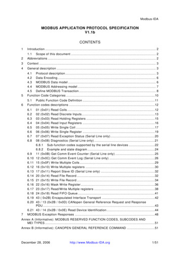
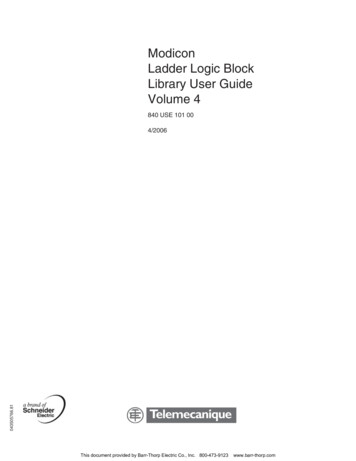
Advantech WebAccess Device Driver Guide1.3Modicon Modbus TCP/IPTCP/IP Comport PropertiesThe TCPIP Comport is usually associated with an Ethernet Network InterfaceCard on the SCADA Node PC. Any TCPIP compatible medium is supported aslong as it complies with Microsoft TCPIP protocol stack.Figure 1.1 TCPIP Comport properties1.3.1 Comport NumberThe Advantech WebAccess COM Ports are “virtual” in the AdvantechWebAccess configuration for TCP/IP. The Advantech WebAccess driver willsearch all NIC (Network Interface Cards) to find the addressed devicesregardless of the configured Comport.For the Modbus TCP/IP driver, it is recommended to use a Com Port numbergreater then 2 and that does not utilize an actual Serial com port (e.g. COM1,COM2, etc) on the SCADA Node.1.3.2 DescriptionThis is an optional field used for user reference.1.3.3 Scan TimeThis is the time in milliseconds to scan the PLC. This must match the abilityof the PLC to respond.Version 4.5 rev 0Advantech Corp., Ltd.page 7
Advantech WebAccess Device Driver GuideModicon Modbus TCP/IPIf the PLC cannot respond as fast as the SCAN Time entered, AdvantechWebAccess will scan at a slower rate.Scan Time is also network dependant, it is possible to enter a Scan Timefaster than your network can respond, Advantech WebAccess will poll alldevices and tags on the Comport before starting a new scan.1.3.4 TimeoutTimeout is the time waited before re-sending a communications packet thatdid not have a reply.Timeout specifies how long the software waits for a response to a datarequest, specifically to wait for a reply from one packet. A recommendedvalue is 7 to 10 ticks, longer if the communication device is slow. This isprotocol dependent: some protocols do not allow changes in time out.Combined with Retry count, Timeout also determines time to consider adevice or port as BAD. Timeout is the time to wait since last communicationpacket sent without a reply. Time is in milliseconds. The slow or poor qualitycommunications require longer timeout. The faster the communicationsnetwork or device, the shorter the timeout required. Shorter timeouts notifyoperators of communications failure more quickly.TimeOut, multiplied by Retry Count plus scan time, is how long AdvantechWebAccess will wait before it considers a device bad. Advantech WebAccesswill send a packet, wait for the TimeOut for a reply. If retry count is non-zero,Advantech WebAccess will repeat the request, wait the Timeout, and repeatfor the number of Retry Times. A device is marked Bad (or Failed) after thenumber of Retries fail.In the example above, Scan Time is 1 second, Retry Count is 3, and Timeoutis 200, Advantech WebAccess will: Waits 1 second Send a packet. Wait 200 Milliseconds for a reply. Send a packet again if no reply. Wait 200 Milliseconds. Send A Packet a third Time if no reply Wait 200 Milliseconds. Mark the device Bad (Failed) if no reply.In the above example, after approximately 1 .6 seconds after a devicefails, Advantech WebAccess will mark it bad.Version 4.5 rev 0Advantech Corp., Ltd.page 8
Advantech WebAccess Device Driver GuideModicon Modbus TCP/IP1.3.5 Retry CountNumber of times to retry communications if no reply is received from a device.Combined with Timeout, also determines time to consider a device or port asBAD.In addition, Indicates the number of times after the first attempt has failedthat communication should be attempted before indicating a failure.Specifically, how many times to send a single packet after the field devicefails to respond to the first packet. After the retry count is exceeded, all thetags in the packet are marked with asterisks and the next packet of requestsis sent. A reasonable value is 3 to 5 times. After this number of tries, the tagsin this packet are marked as "fail to respond" (i.e. asterisks) and are disabled.In reality, increasing the number of retries hides failures on the part of thefield device to respond to a request. Essentially, increasing the retries givesthe field device more chances to reply.1.3.6 Auto Recover TimeAuto Recover Time is the time to wait after a Device is marked Bad (or Failed)before re-initializing communications. Advantech WebAccess will mark thedevice good, send a packet and begin the whole retry / timeout processabove.In the above example fro Timeout, Advantech WebAccess will wait 1 minuteafter a device fails before retrying communications. Every One minute thedevice will go Good, 1.6 seconds later it will be marked Bad if it is still failed,repeat.If communications to the PLC is unusually slow due to hardware,communications or network issues, you might consider increasing this value.If communications to the PLC or RTU fails frequently, you may want todecrease this number in order to have Advantech WebAccess try to reestablish communications sooner.If communications to the PLC, RTU or device Fails (i.e. exceeds Timeout)Advantech WebAccess will wait the Auto Recover Time before trying to reestablish communications.1.3.7 Backup PortThis enables a redundant communications path to the Device. Ifcommunications cannot be established through this Comport, AdvantechWebAccess will try a second Comport, specified as the Backup Port. You mustconfigure the backup Port number in Advantech WebAccess, but without anydevices on it. Usually the device must have two comports also. Not all DeviceTypes support a backup Port.The Backup Port is usually configured as the same type. However, someDevice Types allow the backup port to be another physical type; for example,Modicon Device can use a Serial Port as a backup port to TCP/IP (network)Version 4.5 rev 0Advantech Corp., Ltd.page 9
Advantech WebAccess Device Driver GuideModicon Modbus TCP/IPport. The PLC must have both TCPIP Interface and a Serial Interfaceconnected to the SCADA node, in this example.Version 4.5 rev 0Advantech Corp., Ltd.page 10
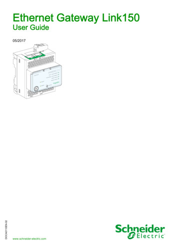
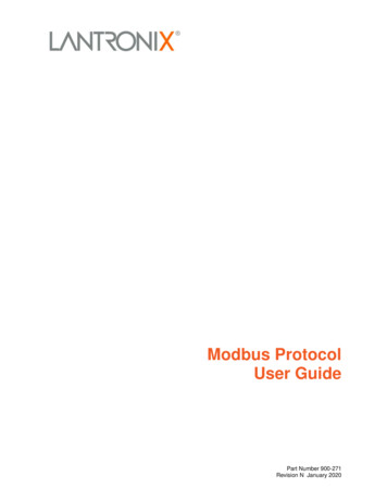
Advantech WebAccess Device Driver Guide1.4Modicon Modbus TCP/IPDevice Properties - ModiconAdd your device to the TCPIP Port, by selecting the Serial Port you haveconfigured, then select Add Device.To modify an existing Device, Select Device Properties. The DeviceProperties Page for a Serial Type Device appears.Figure 3-12Modicon - Modbus TCPIP deviceDevice Name is any user-defined name. See Device Name for moreinformation.Description is a user defined. See Description for more information.Unit Number usually corresponds to the device address number. UnitNumber is used for display purposes in Advantech WebAccess. DeviceNumber 0 uses the Unit Number as the Device Number. The DeviceNumber is used by the communications protocol to the device.Version 4.5 rev 0Advantech Corp., Ltd.page 11
Advantech WebAccess Device Driver GuideModicon Modbus TCP/IPMany Modbus Ethernet devices ignore the Device Number if there is only onedevice at a given IP Address. The Device Type is Modicon.Device Type Modicon. Advantech WebAccess uses the official version theModbus TCPIP specified by the inventors of Modbus, MODICON.IP Address is the IP Address of the PLC, RTU or other device you areestablishing communications with. The Primary IP Address must be specified.The Secondary IP Address is used only if the PLC or device has redundantcommunication cards (i.e. two NICs in the PLC).Port Number is the TCP Port (or UDP port) of the PLC. The Primary must bespecified. The Secondary is used only if a Secondary IP address is used.Device Address is the Modbus Device Address (0 - 255) used by the ModbusRTU protocol. How this is handled varies by device / manufacturer. ManyModbus TCP/IP devices ignore this Device Address (the Modbus RTU Address).Some Modbus TCP/IP devices have multiple PLCs/ RTUs at the same IPAddress, and use the Device Address to route to the correct PLC sharing thesame IP address.Use UDP: The default protocol of the Advantech WebAccess TCP/IP driver isTCP. However, some devices use UDP. If the PLC or Device uses UDP, thenyou must specify Use UDP 1 for the Advantech WebAccess configuration ofthis device.Packet Delay (ms): Some devices cannot receive very fast request afterthey respond previous packet. A delay may be required for the next requestfrom Advantech WebAccess for those slow devices, especially for some oldpower meters.Digital block size: Some Modbus compatible devices use only a certain partof a Modbus address or only handle a short data range for data request fromclient. Advantech WebAccess allows users to define the maximum data blocksize for both requested Digital and Analog type data.Analog block size: Some Modbus compatible devices use only a certain partof a Modbus address or only handle a short data range for data request fromclient. Advantech WebAccess allows users to define the maximum data blocksize for both requested Digital and Analog type data.1.4.1 Device NameA Device is a PLC, Controller, VAV or other automation hardware or softwareentity. Device name is a User-assigned name that will appear in the ProjectManager (Configuration Tool) and in runtime VIEW Displays. Choosing adescriptive Name can help technicians identify the location of your device.Changing only the Device Name will rename the existing device.Changing both the Device Name and the Unit Number will make a copy ofthe device (e.g. create another device).Version 4.5 rev 0Advantech Corp., Ltd.page 12
Advantech WebAccess Device Driver GuideModicon Modbus TCP/IP1.4.2 DescriptionUser assigned description up to 70 characters1.4.3 Unit NumberFor Modbus, this must correspond to the Unit Number used in the protocoladdressing. This is the address configured in the device or by a dipswitch onthe device. The range of Unit Number is 0 to 255 for Modbus.This Unit Number will appear on the System Status Display, Point Detail,user-built displays and tags to reference the status of this device.Changing only the Unit Number here will change the existing device.Changing both the Device Name and the Unit Number will make a copy ofthe device (e.g. create another device).1.4.4 Device TypeThis is the communication Driver used to communicate with all devices on thisCom Port. Only one communications protocol is supported on the same COMport. Once a Device Type is created on a COM port, the Device Type ofadditional devices will be limited to this Device Type.To use another communications device, you must configure another COMport. Multiple TCP/IP type Com Ports can be added which use the sameTCP/IP Network Card on your PC.1.4.5 Com PortCom Port is the Advantech WebAccess COM Port Number. If it is a TCP/IPtype Port, Advantech WebAccess will search all network Cards on your SCADANode PC. You can assign multiple IP Addresses to your SCADA Node Networkcard and use a single Network card on your SCADA Node. You can usemultiple TCP/IP type Com Ports in Advantech WebAccess with only a singleNetwork Card on the SCADA Node.1.4.6 Unit NumberUnit Number is the Unit Number used by Advantech WebAccess. The ProjectManager will force you to use a unique unit number for each Comport. Therecan be multiple PLCs/RTUs on the same comport, each with a unique UnitNumber. There cannot be multiple PLC's / RTU's on the same Com Port withthe same Unit Number.1.4.7 Device AddressDevice Address is the Modbus Device Address (0 - 255) used by the ModbusRTU protocol. How this is handled varies by device / manufacturer. ManyModbus TCP/IP devices ignore this Device Address (the Modbus RTU Address).Some Modbus TCP/IP devices have multiple PLCs/ RTUs at the same IPAddress, and use the Device Address to route to the correct PLC sharing thesame IP address.Version 4.5 rev 0Advantech Corp., Ltd.page 13
Advantech WebAccess Device Driver GuideModicon Modbus TCP/IPIf the Device Address is 0, Advantech WebAccess uses the Unit Number asthe Device Address.1.4.7.1Multiple Devices with same Device AddressIf you have multiple devices with the same Device Address (e.g. Modbus RTUaddress 0 - 255), your options are:1. Configure a Different Advantech WebAccess Unit Number for eachdevice and enter the actual Device Address in the Device Address Field.2. Configure Multiple Comports and place the devices on separatecomports so that each comport has no device with the same UnitNumber. (This is especially true if the device address is 0).Auto Recover Time is the time to wait after a Device is marked Bad (orFailed) before re-initializing communications. Advantech WebAccess will markthe device good, send a packet and begin the whole retry / timeout processabove. In the above example, Advantech WebAccess will wait 1 minute aftera device fails before retrying communications. Every One minute the devicewill go Good, 1.6 seconds later it will be marked Bad if it is still failed, repeat.1.5Configure a TagSummary of stepsThis example is to configure two Tags that read an Analog Input (Address30003) and an Analog Output (Address 40015).1. Open Internet Explorer.2. Connect to Project Node.3. Start Advantech WebAccess Configuration.4. Select Project.5. Select SCADA Node.6. Select the Modicon Device.7. Select Add Tag.8. From Parameter Pull Down List Select AI. This will configure anAnalog Input. Wait for the Page to update.Version 4.5 rev 0Advantech Corp., Ltd.page 14
Advantech WebAccess Device Driver GuideModicon Modbus TCP/IP9. Optionally, select ALARM from the ALARM pulldown list. Wait for thePage to update with a PINK highlight around alarm (an additionalAlarm Fields at bottom of page).10. Enter a Tagname users can use to identify this Analog Inputmeasurement. For example, if this is a Flow measurement, enterFlow1.11. Edit the Address to the actual address. From the example, Enter:3000312. Enter a Description. This will help identify this tag to Users andOperators. For example, enter Boiler #1 Steam Flow.13. Optionally enter, Scaling, Span Hi, Span Low, Engineering Units, andAlarms; enable data logging, etc.14. Press Submit.15. From Parameter Pull Down List Select AO. This will configure anAnalog Output. Wait for the Page to update.16. Optionally, select ALARM from the ALARM pulldown list. Wait for thePage to update with a PINK highlight around alarm (and additionalAlarm Fields at bottom of page).17. Enter a Tagname users can use to identify this Analog Outputmeasurement. For example, if this is a signal to a Valve, enter Valve1.18. Edit the Address to the actual address. From the above example,Enter: 4001519. Enter a Description. This will help identify this tag to Users andOperators. For example, enter Boiler #1 Steam Valve.20. Optionally enter, Scaling, Span Hi, Span Low, Output Limits,Engineering Units, and Alarms; enable data logging, etc.21. Press Submit.Congratulations! You have just configured a Measurement and Output Tags toModbus device.1.6Step by Step GuideIt is recommended to use a Modbus PLC with TCP/IP communications. If aPLC is not available, it is recommended to install the Modbus TCP Simulatorsoftware on the student’s PC. See the Appendix for more information on theModbus PLC simulator software.Version 4.5 rev 0Advantech Corp., Ltd.page 15
Advantech WebAccess Device Driver Guide1.6.1Modicon Modbus TCP/IPTask 1: Configure a Communication PortFrom the Project Manager (See 2.3.2 Connect to Project Node of theEngineering Manual, if you need help connecting)1. Select your SCADA node under the Project/Node list.2.Select Add ComportThis can take a long time while tables are created in the database onthe Project Node / Web Server.Warning – if multiple students are using a single project node that isusing a 10-client limit for IIS, pressing Add Comport willopen a new connection each time it is pressed. Be patient ifyou are sharing a Project Node with other students and donot press Add Comport more than once, otherwise you willget the error:The page cannot be displayedThere are too many people accessing the Web site at this time.3.Version 4.5 rev 0The Create New Comport page appears.Advantech Corp., Ltd.page 16
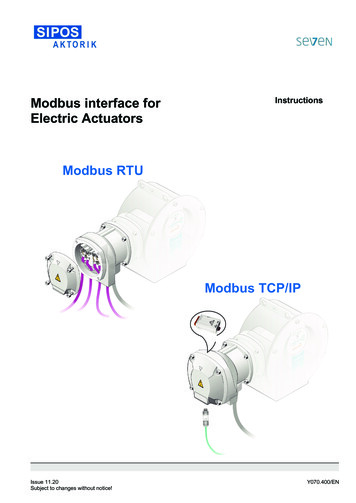
Advantech WebAccess Device Driver Guide4.Modicon Modbus TCP/IPSelect the TCP/IP as the Interface Name for this Comport. (Alsocalled the Comport Type).The fields change depending on the Comport Type.5. The TCP/IP Comport Properties page appears.Version 4.5 rev 0Advantech Corp., Ltd.page 17
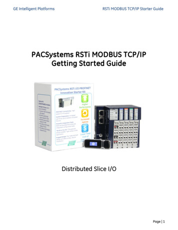
Advantech WebAccess Device Driver GuideModicon Modbus TCP/IPTCPIP - TCP/IP (transmission Control Protocol / Internet Protocol).Specifies a "Virtual Port" that uses the TCP/IP service installed. Doesnot correspond to specific IO card or comport number. Will access anyIO card that uses the TCP/IP service installed on your PC. For adescription of the data entry fields for a TCP/IP Network Interface seethe Engineering Manual, section 3.3.4 TCP/IP Com Port Properties.6. Enter a Comport Number. It is recommended to use a number above2 for TCP/IP ports, so you don't interfere with adding a serialcomport. Most PCs have 2 serial comports, if you configured a TCP/IPcomport as 1 or 2, you would not be able to use that serial comport inthe future. It is not easy to change comport numbers.7. Optionally, enter a Description. This is just for your own reference.8. Enter a Scan Time and select the radio button for the units(Millisecond, Second, Minute or Hour).All devices are scanned at the same frequency on a given comport. AllConstant Scan type Tags are scanned at the same frequency on acomport. Display Scan Tags are scanned at this same frequency, butonly when they appear on a Display.9. Accept the default values for the other fields, or modify them. For adescription of the data entry fields for a TCP/IP Network Interface see,section 3.3.4 TCP/IP Com Port Properties.10. Click Submit.11. The SCADA Node page appears. The Port should appear as a folderunder the SCADA node. (In this example Port 3 under Node 1) in themenu tree at left.1.6.2Task 2: Add Device (a PLC)12. Click on the Port hyperlink (Port3 in this example). The Com PortProperties page opens.Version 4.5 rev 0Advantech Corp., Ltd.page 18
Advantech WebAccess Device Driver Guid
Advantech WebAccess Device Driver Guide Modicon Modbus TCP/IP Version 4.5 rev 0 Advantech Corp., Ltd. page 4 Advantech WebAccess can scan every 100 milliseconds over TCP/IP connections limited only by the PLC, Controller or RTU and the network connection. The Genui