Transcription
GE Intelligent PlatformsRSTi MODBUS TCP/IP Starter GuidePACSystems RSTi MODBUS TCP/IPGetting Started GuideDistributed Slice I/OPage 1
GE Intelligent PlatformsRSTi MODBUS TCP/IP Starter GuideAugust 2012Table of ContentStarter Kit IntroductionPage 3Introduction to RSTiPage 5Getting Started - AssemblyPage 6Configuring RSTiPage 8Downloading RSTi ConfigurationPage 12Proficy Machine Edition MODBUS TCP/IP Network Discovery ToolPage 13Understanding RSTi LED StatusPage 14Power Distribution OptionsPage 16Introduction to IO Guide ProPage 17RSTi Part NumbersPage 19Sample RSTi ConfigurationPage 20Modbus TCP Network Interface Specifications and DrawingPage 24PROFINET Network Interface Specifications and DrawingPage 21PROFIBUS DP Network Interface Specifications and DrawingPage 22DeviceNet Network Interface Specifications and DrawingPage 23Modbus Serial RS-232 Network Interface Specifications and DrawingPage 25Modbus Serial RS-485 Network Interface Specifications and DrawingPage 26Ethernet IP Network Interface Specifications and DrawingPage 27EtherCAT Network Interface Specifications and DrawingPage 28CANOpen Network Interface Specifications and DrawingPage 29CC-Link Network Interface Specifications and DrawingPage 30Discrete Inputs Specifications and DrawingsPage 31Discrete Outputs Specifications and DrawingsPage 34Analog Inputs Specifications and DrawingsPage 37Analog Outputs Specifications and DrawingsPage 40Serial Communications Module Specifications and DrawingsPage 43Motion Modules – High Speed Counting Specifications and DrawingsPage 45Motion Modules – PWM and Pulse Train Specifications and DrawingsPage 48System Modules – Power Distribution, Bus Power BoosterPage 49Page 2
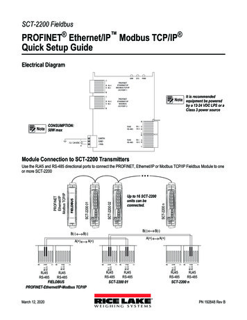
GE Intelligent PlatformsRSTi MODBUS TCP/IP Starter GuideRSTi MODBUS TCP/IP Starter KitThe RSTi MODBUS TCP/IP Starter Kit includes the following: Innovation Starter Kit Flash Drive: The Flash drive includes various RSTi tools. RSTi MODBUS TCP/IP Network Interface module (Part Number STXPNS001) RSTi 8 points discrete input module, 24VDC positive logic (Part Number ST-1218) RSTi 8 points discrete output module, 24VDC source, 0.5amps (Part Number ST-2328) RSTi 4 channels analog input module, 4-20ma current (Part Number ST-3214) RSTi 2 channels analog output module, 4-20ma current (Part Number ST-4212)Items required that are not included in the starter kit: DIN rail minimum length 6 inches long (150mm) Narrow blade screwdriver or other tool to 1/8 to 1/16 inches (3mm to 4mm) wide for depressing thespring clamp wiring terminal 24VDC power supply (minimum 1.5 amp, recommend 2 amps or larger Controller with MODBUS TCP/IP connectivity Ethernet cableItems on Innovation Starter Kit Flash Drive: RSTi Modbus Serial and Ethernet Network Interface Manual RSTi PROFINET Interface Manual (GFK-2746) RSTi PROFIBUS Network Interface Manual RSTi DeviceNet Network Interface Manual RSTi I/O Manual (GFK-2745) RSTi CAD drawings RSTi data sheets RSTi IO Configuration Tool for DeviceNet, PROFIBUS, CANOpen, Ethernet IP, Modbus TCP and Modbusserial PROFINET GSDML file PROFIBUS GSD filePage 3
GE Intelligent Platforms RSTi MODBUS TCP/IP Starter GuideRXi Controller data sheets and manualsRXi IPC data sheets and manualsGE Control Solutions CatalogGE Automation SolutionsProficy MAChine Edition programming tool (45 day free evaluation)And other toolsPage 4
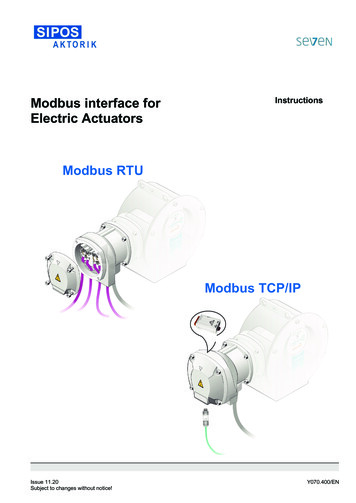
GE Intelligent PlatformsRSTi MODBUS TCP/IP Starter GuideKey Features of the RSTi network Interface and I/O ModulesThe RSTi innovative design enables module power, communications and field power to be passed from onemodule to the next. The RSTi mechanical design provides integrated mechanical interlocking for securingmodule to module and modules to DIN rail locking.Module Power and SystemPowerPin 0 (24VDC) and Pin 1 (0VDC)5VDC Bus pinspasses power fromone module to thenext.Field GroundPin 2 and Pin 3Field Power (Field Power Supplyshould be independent ofModule System PowerPin 4 and Pin 5 (0VDC)Pin 6 and Pin 7 (24VDC)Communicationspassed from onemodule to the next.Field Bus powerpassed from onemodule to the next.Page 5
GE Intelligent PlatformsRSTi MODBUS TCP/IP Starter GuideGetting StartedBuilding the RSTiStep 1: Open the individual boxes and remove modules.Step 2: Attaching the MODBUS TCP/IP network adapter to the DIN rail:Remove the end cover from the right side of the MODBUS TCP/IP Network Interface module (PartNumber STXMBE001) by sliding the end cover up. On the bottom of the network adapter release theDIN rail locking mechanism by flipping the blue lever downward. Place the network interface moduleon the DIN rail and engage the DIN rail locking mechanism by flipping the blue lever back to theoriginal position. The module should now be firmly secure on the DIN rail.Step 3: Attaching the first I/O module:Open the DIN rail locking mechanism on the bottom of the ST-1218 I/O module by flipping the bluelever downward. Slide the I/O module onto the network interface module, from top to bottom, until itis securely on the DIN rail. Lock the I/O module onto the DIN rail by engage the DIN rail lockingmechanism. (Flip the blue lever back to the original position).Note: The RSTi does not limit the sequence of the I/O modules. For the purpose of the startup guide we willplace the modules in the following sequence.1. MODBUS TCP/IP Network adapter (STXMBE001)2. 24VDC discrete input module (ST-1218)3. Analog input module (ST-3214)4. Analog output module (ST-4212)5. 24VDC discrete output module (ST-2328)6. End cap coverStep 4: Attach the remaining modules following the sequence in Step 3. Once all modules are securelyattached to the DIN rail place the end cap cover on the right most module.Page 6
GE Intelligent PlatformsRSTi MODBUS TCP/IP Starter GuideStep 5: Attaching 24VDC Power to the NetworkInterface:Connect 24VDC from the power supply tothe terminal 0 of the MODBUS TCP/IPNetwork Interface Module by pushing in onthe spring clamp release button (Red).Attach 0VDC power from the power supplyto the terminal 1 of the MODBUS TCP/IPNetwork Interface Module by pushing in onthe spring clamp release button (Black)Note: The 24VDC power is used to power up thenetwork interface module. Internally the24VDC is converted to 5VDC that is used forthe network interface module and is alsotransferred to all the I/O modules attachedto the network interface. If field devices like motors and switches are going to be wired to the RSTiStarter Kit a separate 24VDC power supply is required and should be connected 24VDC to terminal 6and 0VDC to terminal 4. Attach terminal 2 to earth ground.Step 6: Apply power to the RSTi and connect the Ethernet cable from the PC to the RSTi Modbus TCP/IP .The following LEDs should be observed on the RSTi Network Interface and I/O modules.MODBUS TCP/IP Network adapter (STXMBE001)Mod LED – Steady Green ONLINK LED – Green ON (If LED is off check cable connections to the PC)ACTIVE LED – OFF (LED will be off until the PC sends activity to the RSTi)I/O LED – Green ON indicating that I/O bus is working properly. If off check to make sure themodules are seated properly.Field Power LED – OFF if no power is applied to pins 4 or 5 (Ground) and pins 6 or 7 ( 24VDC)24VDC discrete input module (ST-1218)Status LED – Green ON for normal operation.Input LEDs – OFF unless an input has been connected and in the ON state.Analog input module (ST-3214)Status LED – Green ON for normal operation.Input LEDs – Solid Red ON. No inputs wired to inputs, this is a normal operation. Diagnostics isdetecting no load or open channel.Analog output module (ST-4212)Status LED – Green ON for normal operation.Output LEDs – Solid Green ON. Normal operation.24VDC discrete output module (ST-2328)Status LED – Green ON for normal operation.Output LEDs – OFF. Normal operation.Page 7
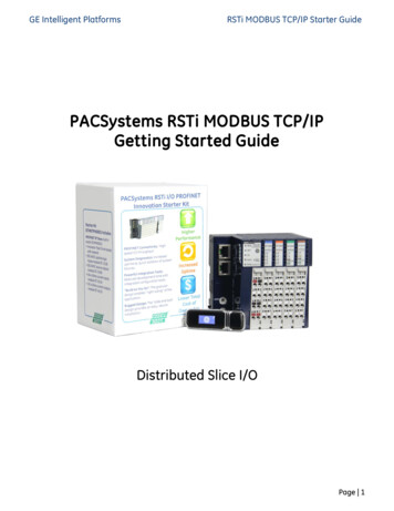
GE Intelligent PlatformsRSTi MODBUS TCP/IP Starter GuideConfiguring the RSTi from a PC running IO Guide ProStep 1: Configuring the RSTi Modbus TCP/IP. Launch IO Guide Pro from either a standalone application orfrom Proficy Machine Edition.Step 2. Go to File, right click on Project File and New.Step 3. Give your project a name like RSTi Starter Kit. SelectModbus TCP/IP for the bus type and click on OK.Page 8
GE Intelligent PlatformsRSTi MODBUS TCP/IP Starter GuideStep 4. Left click on RSTi Starter Kit (or what you called theproject) in the Project Window. Right click on Add and then clickon Network Adapter.Step 5. The Add Network Adapter box should appear. Add the IPaddress that you would like to assign the STXMBE001. For thisexercise 192.168.0.103 will be used. Click OK when IP address isentered.Step 6: Assigning IP Address to the RSTi Modbus TCP : Click onTools and Bootp Server.Step 7: Click on Start Bootp. Reset with Network Default toreset the STXMBE001.Page 9
GE Intelligent PlatformsRSTi MODBUS TCP/IP Starter GuideStep 8: The following will reset the STXMBE001 to factorydefaults. Enter the MAC address of the STXMBE001, locatedbelow the Ethernet port. Click Ok when MAC address isentered. The RSTi STXMBE001 will reset with the lights flashingand returning to their normal state.Step 9: After several seconds the Request History window willdisplay the device. Double Click on the MAC Address of theSTXMBE001 and the Setup IP Address window will appear. TheBootp Server will update every couple seconds so the devicewill reappear.Enter the IP address that you want to use and click onInterface to select the PC network that the STXMBE001 isconnected to.Enter Ok.Close the Bootp Server once the device with the new IPaddresses appears in the Setup History. The STXMBE001 isnow enabled with the new IP address. The IP address is storedin the FLASH memory of the STXMBE001 and will not be lostduring power outage but can be changed at any time usingthe same above procedures. Close GEIP Bootp server whencomplete.Note: You can right click on the IP address in the Setup Historywindow and click on Device Information to see detailedinformation onthe interface.Page 10
GE Intelligent PlatformsRSTi MODBUS TCP/IP Starter GuideStep 10: Connecting to the STXMBE001. The following stepswill establish a connection with the STXMBE001 and enablethe user to view the configuration, monitor the status andsave the configuration to the IOGuidePro.Click Online and select Automatic Scan.Click the Step 2: Scan button. After several seconds theSTXMBE001 should appear with the IP and MAC address.You can double click on the STXMBE001 and the list ofmodules attached the STXMBE001 will appear.Selecting the Overwrite the project radial and the tool willdownload the configuration to the IOGuidePro once the Okis clicked.The Project Window will reflect the configuration of yoursystem.Click Online and click on Start Monitoring. The IOGuideProwill now poll the STXMBE001.You will notice the ACTIVE LED on the STXMBE001 will flashshowing activity.Page 11
GE Intelligent PlatformsRSTi MODBUS TCP/IP Starter GuideBy clicking on the modules and thetabs in the view window the usercan see a wide range ofinformation.Image tab shows moduledescription, image and specificationdata.By clicking on the modules in theProject Window such as STXMBE001the Image tab will show themodules along with loading of the5VDC bus and the dimensions.Note: The current modules consume 300mA of the 1500mA availablefrom the STXMBE001. If this data had been close to the 1500mA limit awarning would pop up. When this occurs you should add a ST-7511(with module ID and occupies a bus address) or ST-7111 (without moduleID and does not occupy a bus address). The ST-7x11 module must beleft of the module that exceeded the 1500mA. The ST-7x11provides anadditional 1500mA to all modules to the right of the ST-7x11.Process Image tab displays the individual parts, data types and values.When in the Monitoring mode it will display the status of inputs andoutputs.The Parameter tab provides key information such as firmwarerevision, date of revision and other system status of the modulesselected in the Project Window.Page 12
GE Intelligent PlatformsRSTi MODBUS TCP/IP Starter GuideThe Address Map tab lays out the addressing of each module thatdata will be mapped to.The Comment tab enables the user to document the application.The text is saved in the project.Transferring Data from RSTi to a controllerI/O Process Image MapAn IO module may have three types of data as I/O data, configuration parameter and memory register. Thedata exchange between network adapter and IO modules is done via an I/O process image data by Busprotocol. The following figure shows the data flow of process image between network adapter and IOmodules.Page 13
GE Intelligent PlatformsRSTi MODBUS TCP/IP Starter GuideControlling and Monitoring I/O from IOGuideProThe following steps will enable the user to exercise inputs and outputs using the Modbus TCP commands. TheModbus Communications window in the Tools tab will enable you to enter the functions.Page 14
GE Intelligent PlatformsRSTi MODBUS TCP/IP Starter GuideReading Hex data to and from the STXMBE001The following example demonstrates how the input and output data is packed into the Hex addressing whenreading from the STXMBE001 Modbus TCP network interface configured as Uncompressed (The default for theSTXMBE001 is Uncompressed Input Processing). It is important to note that modules with only 4 or 8 bits ofdata, such as a discrete in or output module, will have their data packed the next modules word data.Starter Kit Memory Addressing Example with the following: Discrete inputs (0) and (5) ON, on ST-1214 Analog inputs channels (0) 10.0mA and channel (1) 20mA, on ST-3214 Analog outputs channels (0) 10.0mA and channel (1) 20mA, on ST-4212 Discrete outputs (1), (2) and (4) forced ON, on ST-2328All address are in HexReading Input Registers(Function 4) the first 3 Hex wordsfrom STXMBE001.Hex 000F FF05 FE21ST-1214Discrete Input(8 Points)Hex 000F FF05FE21ST-3214Analog Input(2 channels)Hex 000F FF05FE2121 representsthe inputs (0)and (5) ONChannel (0)10mA000F FF05 FE21Channel (1)20mAWriting Multiple registers(Function 16) first 3 Hex wordsfrom STXMBE001.Hex 0016 05FF 0FFF to setanalog output channel (0) to20mA, channel (1) to 10mA andturn outputs 1, 2 and 4 ON.Reading Discrete Inputs(Function 2) ST-1214 InputModuleHex 21Writing Single Coil (Function 5) asingle output (3) ON ST-2328.Write Hex 1022.The base address is decimal4096 (Hex 1000) 32 (32 bitsused by the analog outputmodule ST-4212) 2 4130 or1022 Hex.Writing Single Register (Function6) 7 mA to channel 2, of ST-4212.Write Hex 0300 to Hex registeraddress 0801.Hex register address 0800 ischannel 1, 0801 is channel 2.Hex register 0802 are the 8 bitsof ST-2328ST-4212Analog Out(2 channels)ST-2328Discrete Out(8 Points)Hex 0016 05FF0FFFHex 0016 05FF0FFFWrites 20mA tochannel (0)0016 05FF 0FFFWrites 10mA tochannel 1Turns outputs 1,2 and 4 ONHex 21represents theinputs (0) and (5)ONHex 1022,Send FF00 toturn ON the firstoutput.Address Hex0801Write Hex 0300for 7 mA ordecimal 768Page 15
GE Intelligent PlatformsRSTi MODBUS TCP/IP Starter GuideStep 1: Open Protocol Messenger by clicking onTools, Protocol Messenger and clicking onModbus.Step 2: Writing a single output ON. The following stepswill turn output 1 ON (second output on ST-2328).The following will allow you to determine the Hex addressthat will be written to based on decimal addressing andthen converting to Hex.The base address is 4096 (Hex 1000) 32 (32 bits used bythe analog output module ST-4212) 1 4129 or 1021Hex.a) In Protocol field select Modbus TCP.b) In IP Address field enter IP address of RSTi ModbusTCP slave device.c) Slave ID: 1d) Select Function: 05, Write Single Coil (1bit output)e) Address (Hex format): 1021 (this will controloutput 2)f) Send Data (Hex) FF00 will turn ON (0000 willturn OFF output 1)g) Click Send.h) You will see the response back from the slavein the Response window.i) Change the Send Data to 0000 and you will seethe output 1 go OFF.Step 3: Reading a single discrete input status. Thefollowing steps will read input status. This assumesinput 0 is wired ON.a) In Protocol field select Modbus TCP.b) In IP Address field enter IP address of RSTiModbus TCP slave device.c) Slave ID: 1d) Select Function: 02, Read Discrete Inputs (inputbit)Page 16
GE Intelligent Platformse)f)g)h)i)j)RSTi MODBUS TCP/IP Starter GuideAddress (Hex format): 0000 (this will read input address 0)Quantity (Dec): Enter 1 bitSend Data (Hex) should be blankClick Send.You will see the response back from the slave in the Response window. Click on radial ByteDec and a1 will appear showing that input 0 is ON.By changing the Quantity (Dec) to 8 and click ByteBit in the Response window. The data should reflectthe status of the 8 inputs on the module 00000001. The 1 represents input zero.Step 4: Writing to analog outputs. The followingsteps will write two analog output channels on the ST4212. The example will write Hex 05FF (10mA) tochannel 0 and Hex 0FFF (20mA)to channel 1a) In Protocol field select Modbus TCP.b) In IP Address field enter IP address of RSTiModbus TCP slave device.c) Slave ID: 1d) Select Function: 16, Write Multiple registers(output words)e) Address (Hex format): 0800 (this will write tostarting address 0800 Hex which is the startingaddress of analog output channel 0)f) Quantity (Dec): Enter 2 wordsg) Send Data (Hex): 0FFF 05FFa. Reading from right to left Hex 05FF will command channel 0 on theST-4212 to go to 10ma Analog out 1, 0FFF(20ma) Analog out 2h) Click Send.For more information on how to read and write to the RSTi Modbus TCP slave device refer to GFK-2799,chapter 4.First two are output module Hex 02, 05FF(10ma) Analog out 1, 0FFF (20ma) Analog out 2View Process ImageCongratulations on a successful RSTi MODBUS TCP/IP hardware configuration.Page 17
GE Intelligent PlatformsRSTi MODBUS TCP/IP Starter GuideUsing Auto Discovery Tool to Find PROFINET Devices on the networkThe Proficy MAChine Edition has a powerful tool that enables the user to see all of the devices on the network.Follow the following steps to use the Auto Discovery Tool:Step 1: Connect the PC directly to the PROFINET controller. Place the MAChine Edition in the Offline mode.Step 2: Left click on the PROFINET Controller and when the pop upappears right click on Launch Discovery Tool.The following should appear in the InfoViewer Window.Step 3: In the Connection Settings change the Connection to Local Area Connection and then click on RefreshDevice-List. The tool will display the devices on the network, Device Name, IP Address, Vendor and DeviceType. The slave devices can be dragged from the list to the PROFINET controller to be configured. Thediscovery tool will not bring over the I/O configuration only the network interface.Page 18
GE Intelligent PlatformsRSTi MODBUS TCP/IP Starter GuideRSTi STXPNS001 Status LEDsRSTi STXPNS001ModuleMOD Status LED(Module status LED)Net Status LED(Network StatusLED)I/O LED indicatesthe status of thenetwork interfaceand the I/O it isconnected to.Port 1 and Port 2Field PowerBefore DownloadAfter DownloadGreen “ON” NormalGreen “ON” NormalNo LED: NormalThis is normalindication untilcontroller isconnected andconfiguration isdownloaded.Green “ON” Flashing(0.5 seconds) Normalwhen CPU in StopmodeGreen “ON” Controllerin RUN mode“OFF” No power orno I/O attached“OFF” No power or NoI/O attachedGreen “ON” I/O Busand Configuration isnormal.Green “ON” I/O Busand Configuration isnormal.“OFF” No cable orPROFINET ControllerattachedGreen “Flashing”PROFINET Controllerattached andactivity.“OFF” no field powerappliedGreen “ON” whenfield power is applied“OFF” No cable orPROFINET ControllerattachedGreen “Flashing”PROFINET Controllerattached and activity.“OFF” no field powerappliedGreen “ON” when fieldpower is appliedCommentsIf OFF check to make sure power ison module. Check wiring. If there isa hardware fault the LED could alsobe off.RED LED solid or blinking is afirmware or hardware fault on theSTXPNS001.If LED is “OFF” after a controllerconfiguration is downloaded, checkcable and rotary switch to make sureit matches device name (STXPNS00101 as example if rotary is in 0 1positions) in the Inspector window forthe STXPNS001.If LED is Flashing RED or solid REDthe configuration did not downloadproperly. Check configuration anddownload again to the controller.“RED” solid or flashing bus orconfiguration error. Checkconfiguration and try downloadingagainNetwork interface requires at leastone I/O module attached to functionproperly.If “OFF” confirm cable is attached toboth ends and controller is poweredand connected.Note: RSTi STXPNS001 does notsupport MRP therefore it should notbe used in a ring.If field power is “ON” but LED is not,check wiring.Field power should be anindependent power source from theNetwork Interface powerPage 19
GE Intelligent PlatformsRSTi MODBUS TCP/IP Starter GuideRSTi ST-xxxx I/O Modules Status LEDsRSTi ST-xxxx I/OModulesStatus LEDDiscrete LEDsAnalog LEDsBefore DownloadAfter DownloadGreen “Flashing”normal. I/O is ok andwaiting forconfiguration.Discrete In: Greenwhen power is “ON”Green “ON” normal.Discrete Out: OffAnalog In:LED Green: NormalDiscrete Out: Off logiccontrol is offGreen when logic isturning output on.Analog In:LED Green: NormalAnalog Out:LED Green: NormaloperationAnalog Out:LED Green: NormaloperationCommentsFlashing Red: I/O bus time outRed: module fault.Discrete In: Greenwhen power is “ON”Analog In:If LED is RED check field wiring foropen wire.Analog Out:LED off module not working properly.Page 20
GE Intelligent PlatformsRSTi MODBUS TCP/IP Starter GuideRSTi Additional Power Module InformationSystem Power: It is recommended that the 24VDC System Power be from an independent power source thanthe Field Bus Power. The separation allows the field power to be turned off without impacting the NetworkInterface. The network interface provides 5VDC to the corresponding I/O modules and each module passesthe 5VDC to the next module.5VDC Booster Module: The ST-7111 (No bus ID type support, does not occupy an address on the bus)or ST-7511 (Uses a bus ID and occupies an address on the bus) are available to boost the 5VDC signalin the event that modules power consumption exceed network interface. The booster module willprovide 5VDC at 1 amp to modules to the right of the booster module. The module requires 24VDCSystem Power. 24VDC Field Power is also required and is supplied to all modules to the right.Field Power: Field Power on the Network Interface is 24VDC and the Field Power is passed from one moduleto the next. The maximum current available on the Field Power Bus is 10 amps.Isolated Field Distribution Module: The ST-7241 (No bus ID type support, does not occupyanaddress on the bus) or ST-7641 (Uses a bus ID and occupies an address on the bus) are available tochange field voltages such as 5VDC, 24VDC, 48VDC or AC with a maximum of 10 amps available on theField Power Bus to the right of the module. The module can also be used when additional current andisolation. The Field Bus on the I/O modules to the right of the Isolated Field Distribution Module willcarry the voltage of the Isolated Field Distribution Module.Shield Termination Modules: The ST-7008 (No bus ID type support, does not occupy an address on the bus)or ST-7408 (Uses a bus ID and occupies an address on the bus) is available to group all shields to the RSTi busground. Modules such as analog and motion could use the module to reduce noise impact on the RSTisystem. Field Bus power is passed through the module to the module on the right.0VDC Distribution Modules 8 points, 10 amps: The ST-7108 (No bus ID type support, does not occupy anaddress on the bus) or ST-7508 (Uses a bus ID and occupies an address on the bus) is available to groupcommons from field devices to simplify wiring. The module commons group is connected to the Field Power0VDC bus. Field Bus power is passed through the module to the module on the right.24VDC Distribution Modules 8 points, 10 amps: The ST-7118 (No bus ID type support, does not occupy anaddress on the bus) or ST-7518 (Uses a bus ID and occupies an address on the bus) is available to group24VDC from field devices to simplify wiring. The module 24VDC group is connected to the Field Power 24VDCbus. Field Bus power is passed through the module to the module on the right.0VDC and 24VDC Distribution Modules 4 points each, 10 amps: The ST-7188 (No bus ID type support, doesnot occupy an address on the bus) or ST-7588 (Uses a bus ID and occupies an address on the bus) is availableto group four 0VDC and four 24VDC from field devices to simplify wiring. The module 0VDC is connected tothe Field Power 0VDC and the 24VDC group is connected to the Field Power 24VDC bus. Field Bus power ispassed through the module to the module on the right.Page 21
GE Intelligent PlatformsRSTi MODBUS TCP/IP Starter GuideIO Guide Pro - Third Party Configuration ToolThe IO Guide Pro enables integrators network independence. I/O systems can be easily configured using thevarious RSTi network interfaces. Changing from Ethernet IP to PROFIBUS is as simple as a mouse click withoutimpacting the rest of the I/O configuration. The tool provides technical data, address mapping, productimage and bus loading.The IO Guide Pro Supports the Following Network Interfaces: DeviceNet STXDNX001 onlyPROFIBUS DP STXPBS001 onlyCANOpen STXCAN001Ethernet IP STXEIP001Modbus TCP STXMBE001Modbus serial RS-232 STXMBS001Modbus serial RS-485 STXMBS002Key Features: Automatic scan Modbus devices onlineConfiguration validationView address mapConfigure parametersDocumentationsPage 22
GE Intelligent PlatformsRSTi MODBUS TCP/IP Starter GuideRSTi Part Numbers:Network Interface Units (*Check for release PROFINET RT Network AdapterPROFIBUS DP/V1 network adapterDeviceNet network adapterMODBUS RS-232C network adapterMODBUS RS-485 network CL001*MODBUS/TCP network adapterEtherCAT Network AdapterEtherNet/IP Network AdapterCANopen network adapterCC-link network adapterST-1124ST-1114ST-12144 points, Negative Logic 5VDC4 points, Positive Logic 5VDC4 points, Positive Logic, 12V/ 24VDCST-1218ST-1228ST-121FST-12244 points, Negative Logic, 12V/ 24V DCST-122FST-1314ST-1324ST-131F4 points, Positive Logic, 48V DC4 points, Negative Logic, 48VDC16 points, Positive Logic, 48VDC (Requiresconnector Type Hirose , 144 points, TTL, 5VDC/20mA Inverting4 points, TTL, 5VDC/20mA Non inverting4 points, Negative Logic, 24VDC/ 0.5AST-2318ST-2328ST-221FST-23244 points, Positive Logic, 24VDC/ 0.5AST-222FST-2414ST-2742ST-2744Isolated Relay Output 4 Points, 230V AC/ 2AST-2748Isolated Relay Output 8 Points, 230V AC/ 2AST-25244 points, Negative Logic, Diagnostics, 24VDC/0.5A4 points, Positive Logic, Diagnostics, 24VDC/0.5A4 points, Negative Logic, Diagnostics, 24VDC/2A4 points, Positive Logic, Diagnostics, 24VDC/ 2A8 points, Negative Logic, 24VDC/ 0.5A8 points, Positive Logic, 24VDC/ 0.5A16 points, Negative Logic, 24VDC/ 0.3A(Requires connector Type Hirose , HIF3BA-20D2.54C)16 points, Positive Logic, 24VDC/ 0.3A (Requiresconnector Type Hirose , HIF3BA-20D-2.54C)Isolated Relay Output 2 points, 230V AC/ 2AST-2792ST-2852Relay Output 2 points, 230V AC/ 2A, ManualTriac Output 2 points, 12V 125VAC/ 0.5AST-3114ST-3118ST-3134ST-3214ST-3218ST-32344 Channels, 0 20mA, 12-bit8 Channels, 0 20mA, 12bit4 Channels, 0 20mA, 14-bit4 Channels, 4 20mA, 12-bit8 Channels, 4 20mA, 12bit4 Channels, 4 20mA, -3274*ST-3708ST-3424ST-34284 Channels, 4 20mA, 12-bit, (Requires SensorConnect 3M Mini-Clamp Plug, 37104 Series)4 Channels, 0 10Vdc, 12-bit8 Channels, 0 10V, 12bitST-34444 Channels, 0 10Vdc, 14-bitST-3808ST-4112ST-41142 Channels, 0 20mA, 12-bit4 Channels, 0 20mA,, 12bitST-4424ST-4474*ST-4212ST-4214ST-4274*2 Channels, 4 20mA, 12-bit4 Channels, 4 20mA, 12bit4 Channels, 4-20mA, 12bit, (Requires SensorConnect 3M Mini-Clamp Plug, 37104 Series)2 Channels, 0 10Vdc, 12-bitST-4491ST-4522ST-46224 Channels, 0 10Vdc, 12bit4 Channels, 0 10Vdc, 12bit, (Requires SensorConnect 3M Mini-Clamp Plug, 37104 Series)1 Channel, 0 10V, 12bit, Manual type2 Channels, -10 10Vdc, 12-bit2 Channels, 0 5Vdc, 12-bitST-49111 Channel, 0 1 A, 12bitDiscrete Inputs8 points, Positive Logic, 12V/ 24VDC8 points, Negative Logic, 12V/ 24VDC16 points, Positive Logic, 12V/ 24VDC (Requiresconnector Type Hirose , HIF3BA-20D-2.54C)16 points, Negative Logic, 12V/ 24VDC (Requiresconnector Type Hirose , HIF3BA-20D-2.54C)4 points, 110V AC (AC 85V 132V)4 points, 220V AC (AC 170V 264V)Digital OutputsST-2424ST-2514Analog InputsST-3802ST-38044 Channels, -10 10Vdc, 12-bit4 Channels, -10 10Vdc, 14-bit4 Channels, 0 5Vdc, 12-bit4 Channels, 0 5Vdc, 14-bit2 Channels, RTD4 Channels, RTD (Requires connector TypeHirose , HIF3BA-20D-2.54C)8 Channels, RTD Connector Type (Requiresconnector Type Hirose , HIF3BA-20D-2.54C)2 Channels, Thermocouple4 Channels, Thermocouple Connector Type(Requires connector Type Hirose , HIF3BA-20D2.54C)8 Channels, Thermocouple Connector Type(Requires connector Type Hirose , HIF3BA-20D2.54C)Analog OutputST-4422Page 23
GE Intelligent PlatformsRSTi MODBUS TCP/IP Starter GuidePID Loop Controllers (*Check release date)ST-3814*ST-3834*1 Loop PID Controller 4 Channels, TC, Temp.Controller, SSR out (DeviceNet only)1 Loop PID Controller 4 Ch. TC, Temp.Controller, Current out (DeviceNet only)ST-3714*ST-3734*1 Loop PID Controller 4 Channels, RTD, Temp.Control, SSR Out (DeviceNet only)1 Loop PID Controller 4 Ch, RTD, Temp. Control,Current Out (DeviceNet only)Serial Interface Modules (ASCII)ST-5211ST-5212ST-5221Serial Interface RS-232C, 1 ChannelSerial Interface RS-232C, 2 ChannelsSerial Interface RS-422, 1 ChannelST-5231ST-5232ST-5101High Speed Counter, 1 Channel, 5VDC 1.5MHzST-5442ST-5111Hi
GE Intelligent Platforms RSTi MODBUS TCP/IP Starter Guide Page 8 Configuring the RSTi from a PC running IO Guide Pro Step 1: Configuring the RSTi Modbus TCP/IP. Launch IO Guide Pro from either a standalone application or from Proficy Machine Edition. Step 2.