Transcription
BiomedicalInstrumentationA. Intro & ECGB18/BME2Dr Gari Clifford(Based on slides fromProf. Lionel Tarassenko)Biomedical Instrumentation B18/BME2
Who am I? UL in Biomed EngDir CDT in Healthcare Innovation @ IBMESignal Processing & Machine Learning forClinical DiagnosticsmHealth for Developing CountriesLow Cost ElectronicsEWH / OxCAHTBiomedical Instrumentation B18/BME2
Vital signs monitoringClinical need Every day, people die unnecessarily in hospitals20,000 unscheduled admissions to Intensive Care p.a.23,000 avoidable in-hospital cardiac arrests per annumBetween 5% and 24% of patients with an unexpectedcardiac arrest survive to dischargeVital sign abnormalities observed up to 8 hoursbeforehand in 50% of casesBiomedical Instrumentation B18/BME2
Identifying at-risk patients Acutely ill patients in hospital (e.g. in the Emergency Dept)have their vital signs (heart rate, breathing rate, oxygenlevels, temperature, blood pressure) continuously monitoredbut Patient monitors generate very high numbers of false alerts(e.g. 86-95% of alarms - MIT studies in ‘97 & ‘06) Nursing staff mostly ignore alarms from monitors (“alarmnoise”), apart from the apnoea alarm, and tend to focusinstead on checking the vital signs at the time of the 4-hourlyobservationsBiomedical Instrumentation B18/BME2
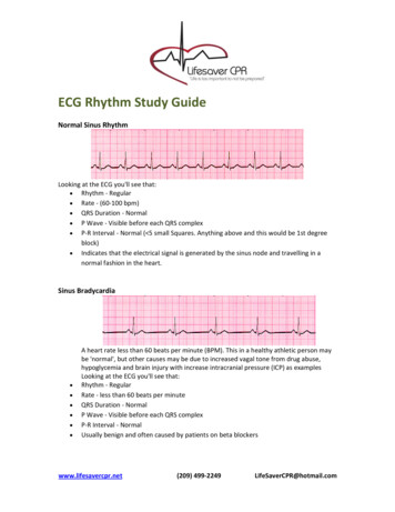
Continuous bedside monitoring inEmergency DepartmentBiomedical Instrumentation B18/BME2
Course Overview1. The Electrocardiogram (ECG)2. The Electroencephalogram (EEG)3. Respiration measurement using Electrical ImpedancePlethysmography/Pneumography4. Oxygen Saturation using Pulse Oximetry5. Non-invasive Blood PressureBiomedical Instrumentation B18/BME2
Course text books Biomedical Engineering Handbook, Volume I,2nd Edition, by Joseph D. Bronzino (Editor),December 1999, ISBN: 0-849-30461-X Medical Instrumentation: Application andDesign, 3rd Edition, by John G. Webster(Editor), December 1997, ISBN: 0-471-15368-0Biomedical Instrumentation B18/BME2
Relevant lecture notes OP-AMP CIRCUITS – Year 1, pages 1 to 42 FILTER CIRCUITS – Year 1, pages 1 to 15 INSTRUMENTATION – Year 2, pages 1 to 4, 17-18, 22to 28 and 38 to 52. Please e-mail val.mitchell@eng.ox.ac.uk if you wouldlike copies of the above. Course website:http://www.robots.ox.ac.uk/ gari/teaching/b18/Biomedical Instrumentation B18/BME2
Quick Vote Do you want all these lectures printed outeach day?(You can uselaptops etc totake notes,just don’tcheck youremail.)Biomedical Instrumentation B18/BME2
ToDo (for you) Sign up on weblearn for revision sessions(15 max per session) B18 (Undergrad) Question sheet 1: three sessions, 9 a.m. - noon on Friday ofWeek 7, in LR4 Question sheet 2: three sessions 9 a.m. - noon on Friday ofWeek 8, in LR4 MSc: Question sheet 1: a single session for all students, 3 - 5 p.m.on Friday of Week 7, in LR3 Question sheet 2: a single session for all students, 3 - 5 p.m.on Friday of Week 8, in LR3Hand in sheets before hand!Biomedical Instrumentation B18/BME2
BiomedicalInstrumentation1. The Electrocardiogram(ECG)Biomedical Instrumentation B18/BME2
The Electrocardiogram If two surface electrodes are attached tothe upper body (thorax), the followingelectrical signal will be observed: This is the electrocardiogram or ECGBiomedical Instrumentation B18/BME2
The origin of the ECG Atrial and ventricular contractions are the resultof carefully timed depolarisations of the cardiacmuscle cells The timing of the heart cycle depends on: Stimulus from the pacemaker cellsPropagation between muscle cellsNon-excitable cellsSpecialised conducting cells (Atrio-Ventricular Node)Biomedical Instrumentation B18/BME2
Important specific structures Sino-atrial node pacemaker (usually)AtriaAfter electrical excitation: contractionAtrioventricular node (a tactical pause)Ventricular conducting fibers (freeways)Ventricular myocardium (surface roads)After electrical excitation: contractionBiomedical Instrumentation B18/BME2
Excitation of the HeartBiomedical Instrumentation B18/BME2
Excitation of the HeartBiomedical Instrumentation B18/BME2
Cardiac Electrical Activity Putting it al together:Biomedical Instrumentation B18/BME2
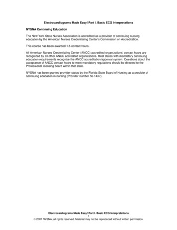
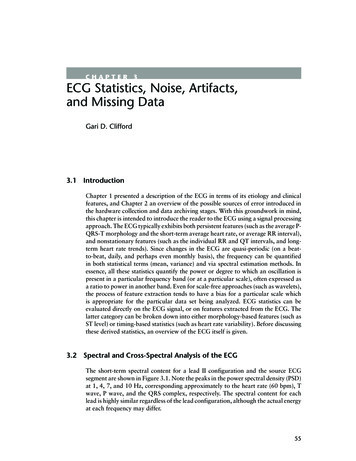
Approximate model of ECG To a first approximation, theheart can be considered tobe an electrical generator.This generator drives (ionic)currents into the upper body(the thorax) which can beconsidered to be a passive,resistive mediumDifferent potentials will bemeasured at different pointson the surface of the bodyBiomedical Instrumentation B18/BME2
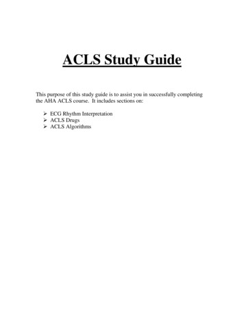
Recording the ECGP1RT1RAP2P1RPLART2P2RLLLPoints P1 and P2 are arbitrary observation points on the torso;RP is the resistance between them, and RT1 , RT2 are lumpedthoracic medium resistances.Biomedical Instrumentation B18/BME2
Typical ECG signalBiomedical Instrumentation B18/BME2
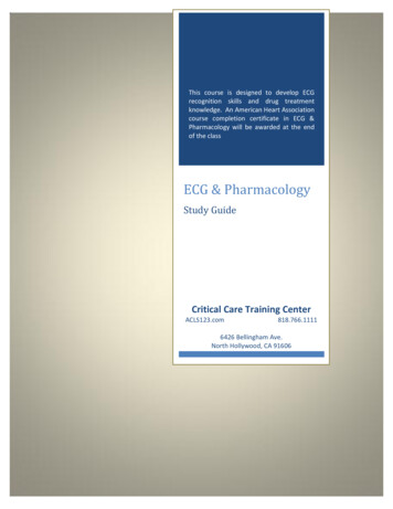
Components of the ECG waveform P-wave: a small low-voltage deflection caused by thedepolarisation of the atria prior to atrial contraction. QRS complex: the largest-amplitude portion of the ECG,caused by currents generated when the ventricles depolariseprior to their contraction.Biomedical Instrumentation B18/BME2
Components of the ECG waveform T-wave: ventricular repolarisation. P-Q interval: the time interval between the beginning of the Pwave and the beginning of the QRS complex. Q-T interval: characterises ventricular repolarisation.Biomedical Instrumentation B18/BME2
Recording the ECG To record the ECG we need a transducer capable ofconverting the ionic potentials generated within thebody into electronic potentials Such a transducer is a pair of electrodes and are: Polarisable (which behave as capacitors)Non-polarisable (which behave as resistors)Both; common electrodes lie between these two extremesThe electrode most commonly used for ECG signals,the silver-silver chloride electrode, is closer to a nonpolarisable electrode.Biomedical Instrumentation B18/BME2
Silver-silver chloride electrode Electrodes are usually metal discs and a salt of thatmetal.A paste is applied between the electrode and the skin.This results in a local solution of the metal in the paste atthe electrode-skin interface. Some of the silver dissolvesinto solution producing Ag ions:Ag Ag eIonic equilibrium takes place when the electrical field isbalanced by the concentration gradient and a layer ofAg ions is adjacent to a layer of Cl- ions.Biomedical Instrumentation B18/BME2
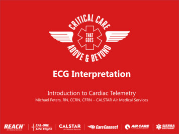
Electrode-electrolyte interfaceElectrodee-eeAgAgAgAgCurrent IAg Cl-Ag Ag Cl-Cl-Cl-Ag GelIllustrative diagram of electrode-electrolyte interface in case of Ag-AgCl electrodeBiomedical Instrumentation B18/BME2
Silver-silver chloride electrode Electrodes are usually metal discs and a salt of that metal.A paste is applied between the electrode and the skin.This results in a local solution of the metal in the paste atthe electrode-skin interface.Ionic equilibrium takes place when the electrical field isbalanced by the concentration gradient and a layer of Ag ions is adjacent to a layer of Cl- ions.This gives a potential drop E called the half-cell potential(normally 0.8 V for an Ag-AgCl electrode)Biomedical Instrumentation B18/BME2
Silver-silver chloride electrode ElectrodeAg Ag Ag Ag Ag Ag Ag Cl-Cl-Cl-Cl-Cl-Cl-Cl-Gel Skin Ag Ag e-The double layer of charges also hasa capacitive effect.Since the Ag-AgCl electrode isprimarily non-polarisable, there is alarge resistive effect.This gives a simple model for theelectrode.However, the impedance is not infiniteat d.c. and so a resistor must beadded in parallel with the capacitor.Biomedical Instrumentation B18/BME2
Silver-silver chloride electrode The double layer of charges also hasa capacitive effect.Since the Ag-AgCl electrode isprimarily non-polarisable, there is alarge resistive effect.This gives a simple model for theelectrode.However, the impedance is not infiniteat d.c. and so a resistor must beadded in parallel with the capacitor.Biomedical Instrumentation B18/BME2
The Overall Model The resistors and capacitors may not be exactly equal.Half cell potentials E and E' should be very similar.Hence V should represent the actual difference of ionicpotential between the two points on the body where theelectrodes have been placed.Biomedical Instrumentation B18/BME2
Electrode placementVI (potential at LA) – (potential at RA)VII (potential at LL) – (potential at RA)VIII (potential at LL) – (potential at LA)The right leg is usually grounded (but see later)Biomedical Instrumentation B18/BME2
ECG Amplification Problems in ECG amplification The signal is small (typical ECG peakvalue 1mV) so amplification is needed Interference is usually larger amplitudethan the signal itselfBiomedical Instrumentation B18/BME2
1st Problem: Electric Field Interference Capacitance between power lines andsystem couples current into the patient This capacitance varies but it is of the orderof 50pF (this corresponds to 64MΩ at 50Hz. recall Xc 1/ C ) If the right leg is connected to the commonground of the amplifier with a contactimpedance of 5kΩ, the mains potential willappear as a 20mV noise input.Electrical power system50 pFRALARLthe 50 Hz interference is common toboth measuring electrodes !(common mode signals)LL5kΩBiomedical Instrumentation B18/BME2
The solution The ECG is measured as a differential signal.The 50Hz noise, however, is common to all theelectrodes. It appears equally at the Right Arm and Left Armterminals.Rejection therefore depends on the use of adifferential amplifier in the input stage of theECG machine.The amount of rejection depends on the abilityof the amplifier to reject common-mode voltages.Biomedical Instrumentation B18/BME2
Common Mode Rejection Ratio(CMRR)vin vcm vdAd & Acmvout Acmvcm AdvdCMRR Ad / Acm(ratio of differential gain tocommon mode gain)Biomedical Instrumentation B18/BME2
Three Op-Amp Differential AmplifierBiomedical Instrumentation B18/BME2
Three Op-Amp Differential AmplifierAd1 v1' v1 v1 v 2 v 2 v 2'i R2R1R2v1' (1 .R2R)v1 2 v 2R1R1R2R2v (1 )v 2 v1R1R1'22 R2v v (v 2 v1 )(1 )R1'2'12 R2Ad1 1 R1Biomedical Instrumentation B18/BME2
Three Op-Amp Differential AmplifierAd1 v1' v1 v1 v 2 v 2 v 2'i R2R1R2v1' (1 R2R)v1 2 v 2R1R1R2R2v (1 )v 2 v1R1R1'22 R2v v (v 2 v1 )(1 )R1'2'1When v1 v2 vcm, Acm 1Biomedical Instrumentation B18/BME2
Three Op-Amp Differential AmplifierAd1 v1' v1 v1 v 2 v 2 v 2'i R2R1R2v1' (1 R2R)v1 2 v 2R1R1R2R2v (1 )v 2 v1R1R1'22 R2v v (v 2 v1 )(1 )R1'2CMRR is product of CMRRfor each input amplifier'1CMRR Ad 1 . Ad 2Acm1 . Acm 2Biomedical Instrumentation B18/BME2
2nd problem: Magnetic Induction Current in magnetic fieldsinduces voltage in the loopformed by patient leadsRA The solution is to minimisethe coil area (e.g. by twistingthe lead wires together)LARLLLBiomedical Instrumentation B18/BME2
3rd problem:Source impedance unbalance If the contact impedances are not balanced (i.e. thesame), then the body’s common-mode voltage will behigher at one input to the amplifier than the other.Biomedical Instrumentation B18/BME2
3rd problem:Source impedance unbalance If the contact impedances are not balanced (i.e. thesame), then the body’s common-mode voltage will behigher at one input to the amplifier than the other. Hence, a fraction of the common-mode voltage will beseen as a differential signal. see problem on example sheetBiomedical Instrumentation B18/BME2
Summary Output from the differential amplifier consists ofthree components: The desired output (ECG)Unwanted common-mode signal because thecommon-mode rejection is not infiniteUnwanted component of common-mode signal(appearing as pseudo-differential signal at the input)due to contact impedance imbalanceBiomedical Instrumentation B18/BME2
Driven right-leg circuitry The common-mode voltage can becontrolled using a Driven right-leg circuit. A small current ( 1µA) is injected into thepatient to equal the displacement currentsflowing in the body.Biomedical Instrumentation B18/BME2
Driven right-leg circuitryLA A1R2RARa-LAA4R1 RaR2RARLLLA2 RLR0Biomedical Instrumentation B18/BME2
Driven right-leg circuitryBiomedical Instrumentation B18/BME2
Driven right-leg circuitry The common-mode voltage can be controlled usinga Driven right-leg circuit. A small current ( 1µA) is injected into the patient toequal the displacement currents flowing in the body. The body acts as a summing junction in a feedbackloop and the common-mode voltage is driven to alow value. This also improves patient safety (R0 is v. large –see notes).Biomedical Instrumentation B18/BME2
Other patient protection (Defib as filteringDigitizationBiomedical Instrumentation B18/BME2
Static defibrillation protection For use in medical situations, the ECGmust be able to recover from a 5kV, 100Aimpulse (defibrillation)Use large inductors and diodesBiomedical Instrumentation B18/BME2
Patient Isolation Opto-isolators DC-DCConvertersBiomedical Instrumentation B18/BME2
RF Shielding & Emissions Electromagnetic compatibility (EMC) Electromagnetic disturbance (EMD) degradation of the performance of a piece of equipment, transmission channel, or system(such as medical devices) caused by an electromagnetic disturbanceElectrostatic discharge (ESD) any EM phenomenon that may degrade the performance of equipment, such as medicaldevices or any electronic equipment. Examples include power line voltage dips andinterruptions, electrical fast transients (EFTs), electromagnetic fields (radiated emissions),electrostatic discharges, and conducted emissionsElectromagnetic interference (EMI) the ability of a device to function (a) properly in its intended electromagnetic environment,and (b) without introducing excessive EM energy that may interfere with other devicesthe rapid transfer of electrostatic charge between bodies of different electrostatic potential,either in proximity in air (air discharge) or through direct contact (contact discharge)Emissions electromagnetic energy emanating from a device generally falling into two categories:conducted and radiated. Both categories of emission may occur simultaneously, dependingon the configuration of the deviceBiomedical Instrumentation B18/BME2
TestingBiomedical Instrumentation B18/BME2
Electrical safety(from Lecture B)Physiological effects of electricity: Electrolysis Neural stimulation Tissue heatingBiomedical Instrumentation B18/BME2
Electrolysis Electrolysis takes place when direct currentpasses through tissue. Ulcers can be developed, for example if ad.c. current of 0.1 mA is applied to the skinfor a few minutes. IEC601 limits the direct current ( 0.1 Hz)that is allowed to flow between a pair ofelectrodes to 10 μA.Biomedical Instrumentation B18/BME2
Neural stimulation An action potential occurs if the normalpotential difference across a nervemembrane is reversed for a certainperiod of time. This results in a sensation of pain (ifsensory nerve has been stimulated) ormuscle contraction (if motor nerve hasbeen simulated).Biomedical Instrumentation B18/BME2
Hazards of neural stimulation The effects of neural stimulation depend on the amplitudeand frequency of the current, as well as the location of thecurrent injection. If the current is injected through the skin, 75 mA – 400 mAat 50 Hz can cause ventricular fibrillation.Beware: under normal (dry) conditions, the impedance of the skinat 50 Hz is usually between 10 kΩ and 100 kΩ; if the skin is wet,the impedance can be 1 kΩ or less. If the current is directly applied to the heart wall (e.g. failureof circuitry in a cardiac catheter), 100μA can causeventricular fibrillation.Biomedical Instrumentation B18/BME2
Tissue heating The major effect of high-frequency( 10 kHz) electrical currents is heating. The local effect depends on the currentamplitude and frequency as well as thelength of exposure. Think about your mobile phone usage Biomedical Instrumentation B18/BME2
Electricity can also be good for you Electrical shock is also applied to patients inclinical practice for therapeutic purposes. These applications make use of the neuralstimulation effect: Pacemakers (to stimulate the heart)Defibrillators (to stop ventricular fibrillation)Implantable Stimulators for Neuromuscular Control(to help paralysed patients regain some neuromuscularcontrol).Biomedical Instrumentation B18/BME2
Electricity can also be good for you Biomedical Instrumentation B18/BME2
levels, temperature, blood pressure) continuously monitored but Patient monitors generate very high numbers of false alerts (e.g. 86-95% of alarms - MIT studies in ‘97 & ‘06) Nursing staff mostly ignore alarms from monitors (“