Transcription
Design of timber structuresExamplesVolume 3EDITION 2:2016Design in the ultimate limit state (ULS)Design of timber jointsComposite timber elementsHorizontal stabilizationDesign for ser viceability (SLS)Design of timber structures – Volume 31
Design of timber structuresExamplesEditorEric BorgströmFacts reviewerEric Borgström and Rune KarlssonDesign and productionProService Kommunikation ABIllustrationsCornelia ThelanderVendela MartinacISBN 978-91-980304-4-0Volume 3EDITION 2:2016PublisherSwedish Forest Industries FederationSwedish WoodBox 55525SE 102 04 StockholmTel: 46 8 762 72 60Fax: 46 8 762 79 90E-mail: info@swedishwood.comwww.swedishwood.com
PrefaceThis is the second revised edition of Design of timber structures Volume 3, Examplespublished in 2015. Rules and standards change in pace with the development of society,why a publication of this type has to be reviewed regularly.The book series Design of timber structures Volume 1–3 has been produced to make iteasier for structural designers to calculate timber structures and it is adapted to Eurocodesand to Swedish application rules EKS 10 (BFS 2015:6). It is being used for higher educationat universities and institutes.In the book series Design of timber structures Volume 1–3 also Volume 1, Structural aspectsof timber construction as well as Volume 2, Rules and formulas according to Eurocode 5are included. All three books are available in English and Swedish. Since the books areavailable in both languages and due to the nuanced content, our goal is that they will playa role for many users on different skill levels.The solved examples in Volume 3 has been compiled by the authors of each chapter in Volume 1respectively. The authors are Roberto Crocetti, Helena Lidelöw, Annika Mårtensson andBert Norlin. Sven Thelandersson at the Faculty of Engineering at Lund University hasbeen responsible for supervision and editing. The solutions to the examples are based onthe rules in SS-EN 1995-1-1, but should not be regarded as an official interpretation of them.Professional application must be based on the original documents published by CEN withcorresponding national application documents for Sweden.More information about wood, glulam and timber construction can be found atwww.swedishwood.com.Stockholm, October 2016Eric BorgströmSwedish Wood4Design of timber structures – Volume 3
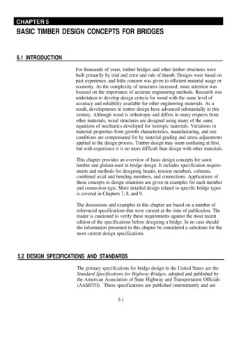
Design of timber structuresVolume 1Structural aspects oftimber constructionEDITION 2:2016Design of timber structuresExamplesVolume 3EDITION 2:2016Design of timber structuresRules and formulasaccording to Eurocode 5Volume 2EDITION 2:2016and design processIntrodu c tion to designred wood produc tsof sawn timber and engineeStruc tural propert iestimber elemen ts in ULSDesign of struc turalDesign of timber jointstsCompo site timber elemenHorizon tal stabiliz ationlityDesign for ser viceabis for housingsystembuildingTimberinfrastr uc tureStruc tural system s fors – Volume 1Design of timber structure1Design in the ultimate limit state (ULS)Design of timber jointsCompo site timber elementsHorizon tal stabiliz ationDesign for ser viceability (SLS)Design of timber structures – Volume 31General conceptsMaterial propertiesBendingA xial loadingCross sec tion subjec ted to shearCross sec tion subjec ted to combined stressesMembers with varying cross sec tion or cur ved shapeSer viceability limit statesConnec tions with metal fastenersWall diaphragmsBracingDesign of timber structuresDesign of timber structures Volumes 1–3 are adapted to Eurocode 5 and the Swedishapplication rules EKS 10 (BFS 2015:6). Volume 1: Structural aspects of timber construction Volume 2: Rules and formulas according to Eurocode 5 Volume 3: ExamplesDimensionering av träkonstruktionerProjektering av träkonstruktionerDimensionering av träkonstruktionerRegler och formlerenligt Eurokod 5Del 1Dimensionering av träkonstruktionerDimensioneringsexempelDel 2Del 3Dimensionering avträkonstruktionerDel 1: Projektering avträkonstruktionerIntroduktion till utformning och dimensioneringKonstruktiva egenskaper för sågat virke och träbaserade kompositprodukterDimensionering av konstruktionselement i brottgränstillståndDimensionering av träförbandSammansatta träelementHorisontalstabiliseringDimensionering för bruksgränstillståndTräbyggnadssystem för bostäderKonstruktionssystem för infrastrukturGenerella begreppMaterialegenskaperBöjningA xiell belastningTvärsnitt utsatt för skjuvningTvärsnitt utsatt för kombinerade spänningarElement med varierande tvärsnitt eller krökt formBruksgränstillståndFörband med förbindare av metallSkiv verkan i träregelväggarStagningDel 2: Regler och formlerenligt Eurokod 5Dimensionering av konstruktionselement av trä i brottgränstillstånd (ULS)Dimensionering av träförbandSammansatta träelementHorisontalstabiliseringDimensionering i bruksgränstillstånd (SLS)Dimensionering av träkonstruktioner – Del 31Del 3: DimensioneringsexempelDesign of timber structures – Volume 35
ContentsContentsThe examples in this textbook are numbered after the matching chapter in Design of timberstructures Volume 1. (Chapter 1, 2, 8 and 9 does not contain designing sections.)Chapter 3, Design in the ultimate limit state (ULS) . 7Example 3.1Design of a straight timber joist. 7Example 3.2Bearing strength for the support of a timber joist. 9Example 3.3Capacity of a notched timber beam. 11Example 3.4Lateral torsional buckling check of a glulam beam. 14Example 3.5Design of a double tapered beam (ULS and SLS). 18Chapter 4, Design of timber joints . 24Example 4.1Design of tie rod connection. 24Example 4.2Design of nailed connection in a Gerber system. 26Example 4.3Design of bolted connection in tension. 29Example 4.4Design of moment resisting column base. 31Chapter 5, Composite timber elements . 36Example 5.1Design of an OSB-webbed I-girder (ULS and SLS). 36Chapter 6, Horizontal stabilization . 44Example 6.1Design of bracing system for wind load on the gable of an industrial hall. 44Chapter 7, Design for serviceability (SLS) . 49Example 7.1Design of a straight timber joist with respect to deflection. 49Example 7.2Serviceability check of floor with timber joists – vibration. 51Example 7.3Serviceability check of floor with glulam elements – vibration. 54Symbols . 586Design of timber structures – Volume 3
Design of a straight timber joist3 Design in the ultimate limit state (ULS)Example 3.1 Design of a straight timber joistA simply supported rectangular joist is subjected to characteristic permanent loading,g k 0,5 kN/m2 and characteristic medium duration variable load qk 2,0 kN/m2.The clear span l is 4,5 m and the joists are spaced at 0,6 m centres.The joist is part of an indoor floor. Service class 1 and safety class 2.Design the joist in structural timber of strength class C24, for bending moment andshear load.SolutionThe characteristic value of bending strength is fm,k 24 MPa.Safety class 2: γd 0,91.The modification factor for load duration and service classes can be taken from Volume 2:Section 3.2, with load duration class M and service class 1 the factor kmod 0,8.Material factor for structural timber, γM 1,3.Size factor for depth greater than 150 mm, k h 1,0 (Volume 2: Section 3.3).It can often be reasonable to let the factor k h adopt the value of 1,0 even for smaller sizesof the joist.Design value of the bending strength:Design value of the load:Design value of the bending moment:Design of timber structures – Volume 37
Design of a straight timber joistThe required section modulus of the joist is given by:A common used width of a timber joist in Sweden is 45 mm. If this is chosen as the width bthe required depth h 214 mm (). A standard section is chosen 45 220 mm. Thisrequires that the joist is braced against lateral torsional buckling by for instance a floor gradedparticle board.Check the shear capacity of the joist.The design value of the shear force:Characteristic value of the shear strength:Thereby is the design value of the shear strength given by:The design value of the shear capacity is given by:According to the national annex in Sweden, at present EKS 10 (BFS 2015:6), the value of Ashould be determined on the basis of bef for a structural element subjected to bending moment.The effective width bef is given by:where kcr 3,0 fv,k 0,75 for structural timber C24, not exposed to precipitation and solarradiation. This gives the following for the design value of shear capacity:This shows that VEd VRd, that is the joist has sufficient shear capacity.Remark: Some way to further reduce VEd is possible, see Volume 2: Chapter 6.8Design of timber structures – Volume 3
Bearing strength forthe support of a timber joistExample 3.2 Bearing strength for the support a of timber joistFor the joist in Example 3.1 in this Volume, check the bearing strength at the end supports.The bearing length has been restricted to 66 mm at each end.The check for bearing strength is given by:The value of the bearing stress is given by:Aef b (l b 0,03) 0,045 (0,066 0,03) 0,00432 m2where b is the width of the beam, l b is the actual bearing length and P Fc,90,d is the force atthe support.b 45 mml b 66 mm(according to Example 3.1)Thus the bearing stress is:The characteristic value of the compressive strength is fc,90,k 2,5 MPa.Because g k qk 0,4 it is possible to set kmod and γM 1,0, according to Volume 1: Section 3.1.3.The design value of the compressive strength is:The factor kc,90 is given by Volume 2: Section 5.2:Design of timber structures – Volume 39
Bearing strength forthe support of a timber joistThe check is then given by:This shows that the bearing capacity at the end supports is sufficient.The example also shows that the fact that only a minor part of the beam is subjected tocompression, allows quite high stresses compared to when a larger area is subjected tocompression. If the joist is supported by a timber top plate, the bearing capacity of thatof course also have to be checked.10Design of timber structures – Volume 3
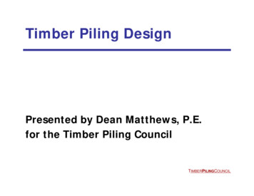
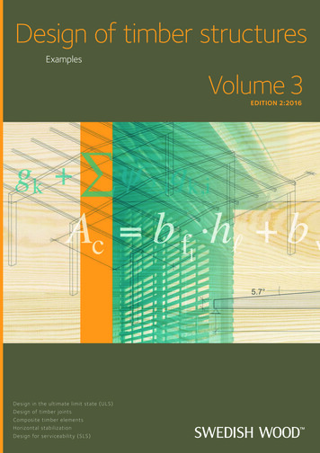
Capacity of a notched timber beamExample 3.3 Capacity of a notched timber beamqd200 mm hefh 315 mm115 mm hnotchx4,9 mx5,2 mFigure 3.1Check the capacity of the beam in the figure above with regard to the ultimate limit state.The beam is made of glulam GL30c and the cross section is 90 315 mm. Service class 1,safety class 3 and load duration class M.The design load has been determined to qd 5,1 kN/m.The design bending moment is:The design shear force is:The characteristic value of the bending strength is fm,k 30 MPa.The modification factor for load duration and service classes can be taken from Volume 2:Section 3.2, with load duration class M and service class 1 the factor kmod 0,8.Material factor for glulam, γM 1,25.Size factor for depths 231 mm h 600 mm, k h (600 315)0,1 1,07(Volume 2: Section 3.3).Design value of the bending strength:Design of timber structures – Volume 311
Capacity of a notched timber beamnamely the bending moment is limited by:namely the moment capacity is sufficient, provided that the beam is not subject to lateralbuckling.Characteristic value of the shear strength fv,k 3,5 MPa.Thereby is the design value of the shear strength given by:The design value of the shear capacity is given by:According to the national annex in Sweden, at present EKS 10 (BFS 2015:6), the value of Ashould be determined on the basis of bef for a structural element subjected to bending moment.The effective width bef is given by:where kcr 3,0 fv,k 0,86 for glulam, not exposed to precipitation and solar radiation. Thisgives the following for the design value of shear capacity:This shows that VEd VRd that is the beam has sufficient shear capacity.Now the notched areas have to be checked. In Eurocode 5: Section 6.5.2, it is stated thatthe following should be verified (also see Volume 2: Section 8.3):where hef is the reduced depth of the beam in the notch and kv is a reduction factor defined asfollows for beams notched on the same side as the support.12Design of timber structures – Volume 3
Capacity of a notched timber beamwhere:iis the notch inclinationhis the beam depth in mmxis the distance from the line of action of the support reaction to the cornerof the notch, in mmkn 6,5 for glulam.Width of the beamb 90 mmDepth of the beamh 315 mmNotch depth at each end of beamhnotch 115 mmNotch inclinationi 0Effective beam depth at each endhef 200 mmRatio of hef hα hef h 0,63Length of the notch fromthe centre line of the end supportx 150 mmThe shear stress is:while the reduced shear strength is given by:This means that the notched beam not has a sufficient capacity.Further calculations give that it could be possible to have a notch corresponding to 16 percentof the total depth, in order to still have the sufficient shear capacity. Alternatively the notchescould be reinforced for example with wood screws.Design of timber structures – Volume 313
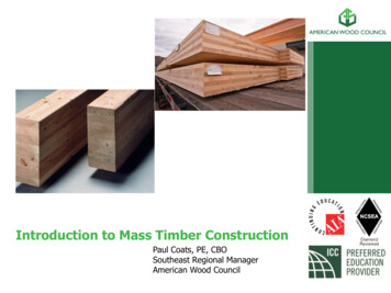
Lateral torsional buckling checkof a glulam beamExample 3.4 Lateral torsional buckling check of a glulam beamhz /2yy /2zFigure 3.2bA simply supported beam is loaded with point loads (coming from columns standing onthe beam). The point loads are of the size Gk 5,25 kN characteristic action (permanentduration) and Qk 14,45 kN variable action (medium-term duration). The beam length isl 10 m. The beam has the dimensions h 630 mm and b 115 mm and is made of glulamGL30c.Check if the beam dimension is enough in service class 1 and safety class 3.(Include the effect of lateral torsional buckling)3.4.1 Geometric properties of the beamWidth of the beamb 115 mmDepth of the beamh 630 mmClear span of the beaml 10 000 mmSection modulus of the beamWy b h2about the y-y axis 63.4.2 Glulam propertiesGlulam GL30c:14Characteristic bending strengthfm,k 30 N/mm2Characteristic shear strengthfv,k 3,5 N/mm2Characteristic compression strengthperpendicular to the grainfc,90,k 2,5 N/mm25th percentile modulus of elasticityparallel to the grainE0,05 10,8 kN/mm25th percentile modulus of shearparallel to the grainG05 0,54 kN/mm2Design of timber structures – Volume 3Wy 7,61 · 106 mm3
Lateral torsional buckling checkof a glulam beamMean modulus of elasticityparallel to the grainE0,mean 13,0 kN/mm2Mean shear modulusGmean 0,65 kN/mm2Mean density of the beamρm 430 kg/m33.4.3 Partial safety factorsEKS 10: Table B-3 for ULS:Permanent actionsγG 1,35Variable actionsγQ 1,5Volume 2: Table 3.1Material factor for glulamγM 1,25Safety class 3γd 1,03.4.4 ActionsSelf weight of the beam(often 5 kN/m3 is assumed as self weightfor timber in general when designing)Design action from the self weightof the beamg k,selfwt b h g ρmg k,selfwt 0,31 kN/mgd,selfwt γd ξ γG g k,selfwtgd,selfwt 0,37 kN/mCharacteristic permanent actionfrom the point loadGk,p 5,25 kNCharacteristic variableaction from the point loadQk,p 14,45 kNDesign action from the point loadfor the critical load case at the ULS(Eurocode 0: Equation 6:10 and EKS 10:Table B-3) using the unfavourablecondition variable actionFd,p γd ξ γG Gk,p γd γQ Qk,pFd,p 1,0 0,89 1,35 5,25 1,0 1,5 14,45 27,98 kNDesign of timber structures – Volume 315
Lateral torsional buckling checkof a glulam beam3.4.5 Modification factorsFactor for medium durationloading M and service class 1(Volume 2: Table 3.2)kmod 0,8Size Factor for depth greaterthan 600 mm (Volume 2: Section 3.3)k h 1,0Lateral stability of the beam(Volume 2: Chapter 4)kcritEffective length of the beam– adopt case for the mostcritical condition – the point load(concentrated load) at mid-span(Volume 2: Table 4.1)l ef 0,8 ll ef 8 mCritical bending stress(Volume 2: Chapter 4 orEurocode 5: Equation 6.32)λrel,m 1,25Relative slenderness for bending(Volume 2: Chapter 4 orEurocode 5: Equation 6.30)Lateral stability factor(Volume 2: Chapter 4 orEurocode 5: Equation 6.34)16Design of timber structures – Volume 3kcrit 0,62
Lateral torsional buckling checkof a glulam beam3.4.6 Bending capacityThe design load case at the ULS will be the result of a combination of self weight of the beamplus the combined permanent and variable point loads at mid span:Design bending momentMEd 74,6 kNmDesign bending strengthfm,y,d 19,20 N/mm2Design bending strength taking lateraltorsional buckling effect into account(Volume 2: Chapter 4)MRd fm,y,d Wy kcritMRd 90,6 N/mm2Bending capacity is satisfactory for glulam, 115 630 GL30c.3.4.7 Shear capacityThe design load case will be the result of combination of self weight of the beam plusthe combined permanent and variable point loads at mid span:Design value for end shear forceVd 15,8 kNModification factor for shear(crack factor)kcr 3,0 3,5 0,86Effective width for shearbef kcr bDesign shear stress(Volume 2: Chapter 6)τd 0,38 N/mm2Design shear strength(Volume 2: Section 3.1)fv,d 2,24 N/mm2bef 99 mmThe beam dimension is sufficient.Design of timber structures – Volume 317
Design of a double tapered beam(ULS and SLS)Example 3.5 Design of a double tapered beam (ULS and SLS) 1 6mhap 1698 mmb 190 mm 2 2,4 m5,7 h 700 mm 20 mFigure 3.3: Geometry of the beam.Loads acting on the beamThe loads considered for the design of the double tapered beam are the following: beam selfweight, roof dead load and snow load. The wind load can be neglected. The centre-to-centredistance between the primary beams is l1 6 m. However, the influence area for a beam isconsidered 10 percent larger than l l1, to take into account the effect of the continuity ofthe purlins over the primary beams. The snow load is reduced to take into account the roofshape factor μ 0,8 5,7 20 0,3 0,8855. Here as an approximation on the safe sidewe calculate with the snow load on the leeward side according to EKS 10 as uniformlydistributed along the whole beam length.Table 3.1Load typeUniformly distributed load[kN/m2]Uniformly distributed load[kN/m]g1k 1,10Beam self weightRoof dead load0,6g2k 3,96Snow1,5s 8,77Load combinationsA possible collapse of the double tapered beam is of such nature that it might involve a highrisk of injury to persons. Therefore, the safety class is assumed to be high (safety class 3),thus γd 1. The beams are assumed to be indoors, in a heated environment. Therefore, theyare characterized by an environment in which relative humidity very seldom, if ever, exceeds65 %. Thus, the service class can be assumed to be 1.18Design of timber structures – Volume 3
Design of a double tapered beam(ULS and SLS)Table 3.2Safety classService classLoad combinations [kN/m]Load durationKmodKdefServiceability limit state (SLS) 1gk (g1k g1k ) 5,1 0,6 1s 8,77 0,6Ultimate limit state (ULS)3 γd 11gd 1 · 1,2 · (g1k g2k) 6,1permanent0,6 3 γd 11qd 1 · [1,2 · (g1k g2k) 1,5 · s] 19,23medium-term0,8 MaterialThe material used for this structure is glulam GL30c (γM 1,25, kmod 0,8).Table 3.3CharacteristicsDesign valuesBendingfm,d 19,2 MPaShearfv,d 2,2 MPaCompression parallel to grainfc,0,d 15,7 MPaCompression perpendicular to grainfc,90,d 1,6 MPaTension parallel to grainft,0,d 12,5 MPaTension perpendicular to grainft,90,d 0,32 MPaModulus of elasticityE0,mean 13 000 MPaShear modulusGmean 650 MPa3.5.1 Bending at critical section (x x0)and at mid-span (x l 2)a. Determination of stressesqdat x x0αat x /2σm,αhaph0bx x0σm,0bσm,0σt,90x /2 Figure 3.4For a symmetrical double tapered beam with constant uniformly distributed load qd,the location of the critical cross section – that is the abscissa where the maximum bendingstress occurs – can be calculated as follows:Design of timber structures – Volume 319
Design of a double tapered beam(ULS and SLS)The corresponding depth of the beam is:The bending moment at the critical cross section is:The corresponding bending stress at the critical cross section is:The bending moment at mid-span is:The corresponding bending stress at mid span:At the mid-span (apex zone), the tensile bending stress shall be magnified by a factor k l to takeinto account of the fact that the depth of the beam is not constant, but it varies linearly and ithas a singularity at the apex. The magnification factor k l increases with increasing roof slopeand it can be obtained from Volume 2: Section 8.2 or Eurocode 5: Equation 6.43. For a slopeα 5,7 k l 1,2.b. VerificationsAt the tapered edge of the beam the bending strength must be reduced by a factor km,α to takeinto consideration the effect of simultaneous action of compression parallel to grain, tensionperpendicular to grain and shear. The reduction factor km,α increases with increasing roofslope and it can be obtained from Volume 1: Figure 3.35. For a slope α 5,7 km,α 0,86.Table 3.4Positionσm,d [MPa]fm,d [MPa]km,αfm,α,d [MPa]Utilization ratiox x016,119,20,8619,2 · 0,86 16,516,1 16,5 0,97x l 212,619,2 12,6 19,2 0,65σm,d design bending stress; fm,d design bending strength; fm,α,d reduced design bending strength (tapered edge).20Design of timber structures – Volume 3
Design of a double tapered beam(ULS and SLS)Lateral torsional bucklingLateral torsional buckling in the double tapered beam (primary beams) may only occurbetween two adjacent purlins, under the condition that 1) the roof is braced in the transversedirection and 2) the purlins are adequately fastened to the primary beams. In that case,the buckling length can be assumed as the centre-to-centre distance between purlins, that isl 2 2 400 mm. Within this distance, the depth of the cross section can be regarded asconstant. The critical bending stress can be calculated according to Volume 1: Equation 3.34:The relative slenderness ratio for bending is defined in Volume 1: Equation 3.30 and the corresponding reduction factor kcrit is defined in Volume 1: Table 3.3:Since λrel,m 0,75, full bending strength can be achieved without risk for lateral torsionalbuckling.It is important to check the shear capacity for tapered beams due to the normally low beamdepth at the supports. Yet this check is omitted in this example.3.5.2Tension perpendicular to the graina. Determination of stressesThe tensile stress perpendicular to the grain can be evaluated by multiplying the bendingstress at mid-span by the factor kp, which can be taken from Volume 1: Figure 3.38:b. VerificationsThe tension strength perpendicular to grain shall be reduced in order to take into accountthe volume effect. The volume of wood which is loaded in tension can be estimated as follows,see Volume 1: Table 3.4:The reduction factor due to volume effect can be calculated according to Volume 1: Equation 3.53:where kdis is a factor that takes into account that the tension stress perpendicular to the grainis not uniformly distributed in the loaded timber volume V.Table 3.5Positionσt,90, [MPa]ft,90,d [MPa]kvolft,90,d red [MPa]Utilization ratiox l 20,210,320,630,63 · 0,32 0,200,21 0,20 1,045Design of timber structures – Volume 321
Design of a double tapered beam(ULS and SLS)Here the need for reinforcement is just about necessary. A calculation with unequal-sidedsnowload according to EKS 10 results in a reduction of the bending moment to 97 % compared to the one in the calculation above. The utilization ratio is then 0,97 1,045 1,01, whatcould be acceptable.Additionally the shear capacity at the supports has to be verified. This is of special importancefor double tapered beams because of their reduced cross sectional height at the supports. Byslopes 1/10 or more the shear stresses at the supports are often designing the beam dimensions.3.5.3 Shear at the supportsSupport reactionAdvantageously the shear force is given by applying the possible reduction according toEuro code 5: Section 6.1.7 (3). With purlins spaced at 2400 mm centres a load on 1 200 mm ofthe primary beam goes directly to the support and does so not contribute to the shear stress.The utilization ratio is then 1,908 1,92 0,99, what is acceptable.3.5.4 Compression perpendicular to the grain at the supportsa. Determination of stressesWe assume that the column supporting the double tapered beam has a cross section190 360 mm. The support length between beam and column is thereforeb l b 190 360 mm2.The compression stress perpendicular to the grain can be evaluated according to Volume 2:Section 5.2 or Eurocode 5: Section 6.1.5.b. VerificationsThe compression strength perpendicular to grain can be magnified by factor kc,90 1,75Because g k qk 0,4 it is not recommended to choose kmod and γM as 1,0.Table 3.622Positionσc,90,d [MPa]fc,90,d [MPa]kc,90f'c,90,d [MPa]Utilization ratiox 02,61,61,751,75 · 1,6 2,82,6 2,8 0,93Design of timber structures – Volume 3
Design of a double tapered beam(ULS and SLS)3.5.5 DeflectionFor a double tapered beam, resting on supports and subjected to a uniformly distributed load q,the deflection w should be evaluated by the following equation, Piazza et al. (2005), seeVolume 1: Section 3.6:where χ 1,2, Iy and A are the moment of inertia and area of the cross section at the supportrespectively, whilst km and kv are defined as:The instantaneous deflections are:- wg,inst – due to self weight- wqs1,inst – due to the variable action qs1 (snow load)With Ψ2,1 0,1 (snow load) and kdef 0,6 (service class 1), the final deflection is:This deflection corresponds to l 249 which is fully acceptable for an industrial building.For schools, stores and similar facilities with higher requirements, it can be con sidered tomanufacture the beam with a precamber of say 70 mm.Design of timber structures – Volume 323
Design of tie rod connection4 Design of timber jointsExample 4.1 Design of tie rod connectionHint: Failure mode (d) in Volume 2: Figure 10.2 is governing the behaviour of the connectionand the rope effect is not necessary to take into account.45 345xx452Figure 4.1A balcony in timber is at the front edge supported by a tie rod made of steel. This steel rod isattached to the floor beam of the balcony with 12 wood screws. The supporting floor beam hasthe dimension 115 270 mm. The wood screws have a length of 60 mm, a diameter of 8 mmand an ultimate strength of 410 MPa. For simplicity the effective diameter def is here assumedto be equal the outer thread diameter d. This information is usually to be found in the declarations from the screw manufacturers. The thickness of the steel plate is 8 mm. The tensileresistance perpendicular to the grain of the floor beam is assumed to be sufficient to withstandthe force from the tie rod.Calculate the maximum load in the tie rod with respect to the capacity ofthe steel-to-wood connection.Spacings and edge distances for the screws are assumed to be adequate.Geometry24Steel thicknesst 8 mmScrew diameterdef d 8 mmScrew lengthl s 60 mmScrew length in the timbert1 l s t 52 mmAngle between force and grain directionα 45 Number of wood screwsn 12Design of timber structures – Volume 3
Design of tie rod connectionCapacity of the connectionCharacteristic density, glulam GL30cρk 390 kg/m3Wood screw strengthfu 410 MPaPartialcoefficient, connectionγM 1,3Material factor for the connection at the ULS,medium term load M, service class 3kmod 0,65Yield moment wood screwMy,Rk 0,3 fu def 2,6My,Rk 2,74 104 NmmEmbeddingstrength parallel fibersf h,0,k 0,082(1 0,01def ) ρkf h,0,k 29,42 MPaSoftwood, correction factork90 1,35 0,015def 1,47Embedding strength inthe direction of the forcef h,α,k 23,82 MPaThe connection is a one sided connection with a thick steel plate, that is failure mode c, d or e,see Volume 2: Figure 10.2 and Volume 1: Table 4.3:Failure mode cFv,Rk,c 9,91 kNFailure mode dFv,Rk,d 4,83 kNFailure mode eFv,Rk,e 5,26 kNCharacteristic capacityFv,Rk min(Fv,Rk,c , Fv,Rk,d , Fv,Rk,e) 4,83 kNDesign capacityFv,Rd 2,42 kNTotal capacity of the connectionFv n Fv,Rd 29,0 kNThe connection can withstand a force of 29 kN.Design of timber structures – Volume 325
Design of nailed connectionin a Gerber systemExample 4.2 Design of nailed connection in a Gerber systemThis connection can advantageously be designed so that the force is being transferred viacompression towards the horizontal parts of the steel, what also is the common procedure inpractice. However in the example this have been ignored and focus is to show how nail designis done.4.2.1 Problem descriptionThe Gerber connection is placed in the outer bay of a beam with a span in the bay of23 000 mm. The beam is loaded with an evenly distributed load.Jointhh 1 305 mmb 215 mm 23 000 mmFigure 4.2:
4 Design of timber structures – Volume 3 Preface This is the second revised edition of Design of timber structures Volume 3, Examples published in 2015. Rules and standards change in pace with the development of society, why