Transcription
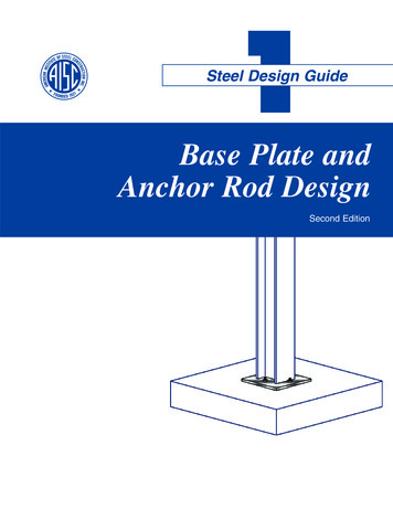
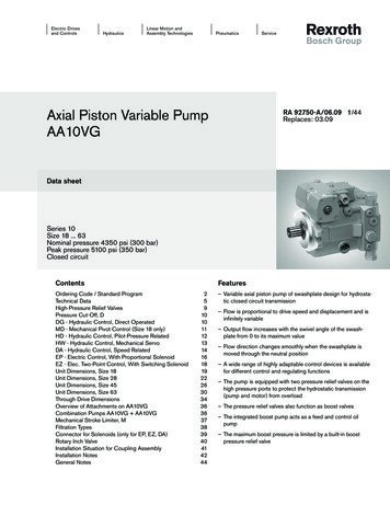
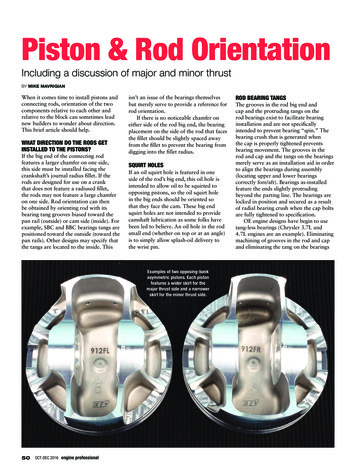
Piston & Rod OrientationIncluding a discussion of major and minor thrustBY MIKE MAVRIGIANWhen it comes time to install pistons andconnecting rods, orientation of the twocomponents relative to each other andrelative to the block can sometimes leadnew builders to wonder about direction.This brief article should help.WHAT DIRECTION DO THE RODS GETINSTALLED TO THE PISTONS?If the big end of the connecting rodfeatures a larger chamfer on one side,this side must be installed facing thecrankshaft’s journal radius fillet. If therods are designed for use on a crankthat does not feature a radiused fillet,the rods may not feature a large chamferon one side. Rod orientation can thenbe obtained by orienting rod with itsbearing tang grooves biased toward thepan rail (outside) or cam side (inside). Forexample, SBC and BBC bearings tangs arepositioned toward the outside (toward thepan rails). Other designs may specify thatthe tangs are located to the inside. Thisisn’t an issue of the bearings themselvesbut merely serve to provide a reference forrod orientation.If there is no noticeable chamfer oneither side of the rod big end, the bearingplacement on the side of the rod that facesthe fillet should be slightly spaced awayfrom the fillet to prevent the bearing fromdigging into the fillet radius.SQUIRT HOLESIf an oil squirt hole is featured in oneside of the rod’s big end, this oil hole isintended to allow oil to be squirted toopposing pistons, so the oil squirt holein the big ends should be oriented sothat they face the cam. These big endsquirt holes are not intended to providecamshaft lubrication as some folks havebeen led to believe. An oil hole in the rodsmall end (whether on top or at an angle)is to simply allow splash-oil delivery tothe wrist pin.Examples of two opposing-bankasymmetric pistons. Each pistonfeatures a wider skirt for themajor thrust side and a narrowerskirt for the minor thrust side.50OCT-DEC 2016 engine professionalROD BEARING TANGSThe grooves in the rod big end andcap and the protruding tangs on therod bearings exist to facilitate bearinginstallation and are not specificallyintended to prevent bearing “spin.” Thebearing crush that is generated whenthe cap is properly tightened preventsbearing movement. The grooves in therod and cap and the tangs on the bearingsmerely serve as an installation aid in orderto align the bearings during assembly(locating upper and lower bearingscorrectly fore/aft). Bearings as-installedfeature the ends slightly protrudingbeyond the parting line. The bearings arelocked in position and secured as a resultof radial bearing crush when the cap boltsare fully tightened to specification.OE engine designs have begin to usetang-less bearings (Chrysler 3.7L and4.7L engines are an example). Eliminatingmachining of grooves in the rod and capand eliminating the tang on the bearings
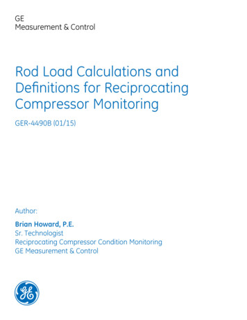
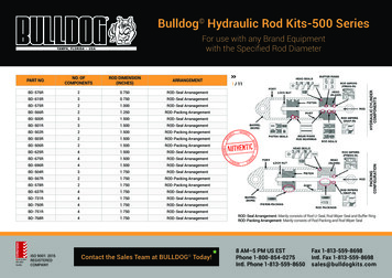
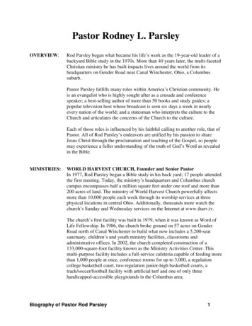
Another example of anasymmetric piston. Noticethat the pin bosses are closertogether to accommodate ashorter (and lighter) wristpin. While it’s difficult to seeby eye, the pin centerline isbiased 0.020” closer towardthe major thrust side inorder to tune the pin’s pivotpoint balance in order tocompensate for the differencein major and minor skirt size/mass.An oil squirthole at therod smallend servesto providelubrication tothe wrist pin.A view of asmall endsquirt hole atthe exterior ofthe small end.A largerchamfered oilhole at the topof the smallend on somerod designsprovides a“funnel” forimproved oilreservoir forfloating pinlubrication.When a piston maker specifies a precise skirt height location for diameter measurement, this representsthe area of the skirt “barrel” profile that will experience the highest cylinder wall loading.Asymmetric pistons may also feature an arrow that indicates piston orientationrelative to the front of the engine. This provides a handy visual aid in installingthe pistons so that the major thrust side skirt faces the major thrust loadwithin the cylinder bore.The underside of this piston features an “L” suffix, indicating that this piston isintended for the left bank of a V engine. Pistons intended for the right bank willfeature an “R” suffix.www.engineprofessional.com51
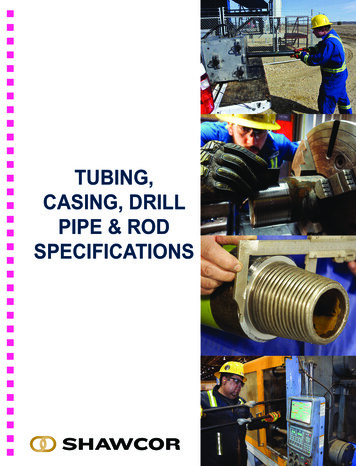
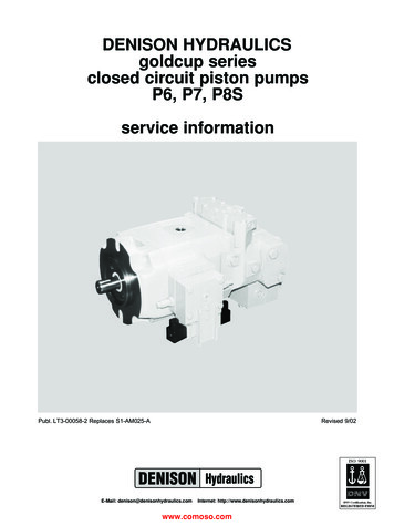
PISTON & ROD ORIENTATIONBY MIKE MAVRIGIANreduces manufacturing cost. Again,the locking tangs only exist to provideassembly alignment. When installingno-tang bearings, they must be centeredon the rod and cap bearing bore surfaces.We’ll be seeing more and more of theseapplications from the OEM side.the left bank and the intake side of theright bank. If the pistons are symmetricand do not feature an offset pin location,piston orientation won’t matter, as longas the valve pockets (if any) are locatedappropriate to the valve locations.ROD OFFSETThe shape, area of mass and weight ofa piston’s skirts play a major role inmanaging friction and in stabilizing thepiston during TDC and BDC transitions.Here we’ll discuss the role of the majorand minor thrust sides of a piston and thedevelopment of asymmetric skirt designsintended to minimize weight whilemaximizing efficiency.Piston skirts are not perfectly round,and each side of the piston experiencesdifferent levels of loading, relative tothe intake and exhaust sides of thecylinders. Skirt design plays a major rolein accommodating these forces in termsof durability and performance, as well aspiston weight.The piston skirt area is slightly“barrel” shaped to provide an adequatesurface load against the cylinder wallwhile reducing friction. The amountof surface area must accommodate theload, while providing piston stability tominimize rocking relative to the pin axisas the piston moves down from TDC andback up from BDC.The piston experiences a “major”and “minor” thrust force at opposingsides of the piston skirts. The majorthrust face is the side of the piston thatreceives the thrust on the power stroke.As viewed facing the front of the engine,if the crankshaft is rotating clockwise, themajor thrust face is on the left side of thecylinder (the exhaust sides of the right/passenger cylinders; and the intake sidesOffset designed into a rod places eitherthe large or small end centerline slightlyoffset from the centerline of the rodbeam. This is to accommodate enginedesigns where the centerline of thecylinder bore is slightly offset from thefore/aft intended location of the rodbearing radial centerline. Depending onthe specific engine deign, the rod mayfeature an offset of as much as 0.100” ormore.If in doubt, during test fitting, verifythat the small end of the rod is centeredon the wrist pin between the pin bosses.DO REVERSE ROTATION ENGINES GETPISTONS INSTALLED BACKWARDS?On a reverse-rotation engine (where thecrank rotates counterclockwise whenviewed from the front of the engine),rods are installed similar to a clockwiserotation engine, where the largerchamfer side of the big end faces thefillet. However, if the pistons feature anoffset pin, the piston must be installed“backwards” relative to installationin a clockwise engine. The pin offsetis biased toward the major thrust sideof the piston. In a clockwise-rotatingengine, the major thrust side is at theintake side on the left (driver) bank andthe exhaust side on the right (passenger)bank. In a reverse-rotation engine, thethrust sides are opposite: the major thrustside will now be at the exhaust side ofSKIRTS AND MAJOR/MINOR THRUSTA view of the major thrust side. Note the width of the skirt.(Courtesy JE)52OCT-DEC 2016 engine professionalof the left (driver) side cylinders. Theminor thrust side experiences force on thecompression stroke.This difference in force at each sideof the piston is caused in part by theoperating angles of the connecting rodduring its travel.During the firing cycle, the loadexperienced on the major thrust side skirtcan be as much as 10 times greater thanthe load experienced on the minor thrustside skirt. The difference in skirt loadingwill vary depending on variables such ascrankshaft stroke, connecting rod lengthand peak cylinder pressures.Since asymmetric pistons are bankspecific, each piston will be labeled forright or left bank position. The domemay also feature a laser-etched arrowthat indicates piston orientation towardthe front of the engine.Major thrust sideWhen the piston is pushed down duringthe power stroke, it experiences resistanceas it attempts to turn the crankshaft. Asload increases, the amount of resistanceincreases. During this resistance, theBy contrast, this is a view of the minor thrust side of the same piston.Note the reduced width of the minor-side skirt. (Courtesy JE)
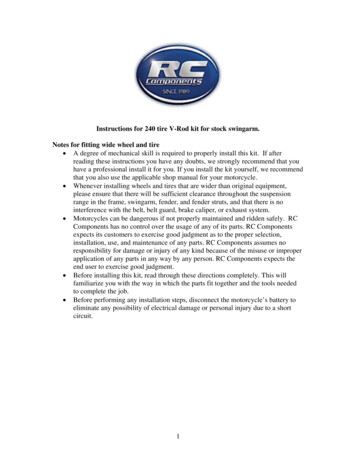
A rod bigend’s nonchamferedside facesthe adjacentrod big end.piston side load is forced to one side (themajor thrust side), which places more force(with subsequently increased friction andpotential wear) on the thrust side of thecylinder wall. If the piston dome featuresa reference dot or other mark, it’s criticalto install the piston with this mark facingthe appropriate direction (usually the markindicates the side of the piston that shouldface forward). The piston side loads on themajor side tend to increase with the useof longer stroke and with forced/boostedinduction pressures. Again, assuming aclockwise-rotating crankshaft, the majorthrust side will be at the exhaust side of theengine’s right bank and the intake side ofthe left bank.Minor thrust sideThe piston’s minor thrust side is directlyopposite of the major thrust side. Theminor thrust side is forced to the oppositeside of the cylinder wall as it moves upon the compression stroke, due to theresistance generated by meeting the air/fuelmixture. The role of the minor thrust sideis basically to provide piston stability, withthe major thrust side taking the brunt ofthe cylinder wall contact. Due to its “lessforce” role, the minor thrust side skirtcan be narrower, saving weight, withoutsacrificing strength.In order to address, or “fine tune”these forces between the major and minorthrust sides, asymmetric pistons have beendeveloped that feature two different-sizeskirts.This style of pistons is specificallydesigned with a larger (wider) skirt onthe thrust side and a smaller skirt on theminor thrust side. This provides a greater“footprint” for the major thrust side,where it’s needed the most to handle ahigher degree of thrust loading, and allowsIf a largechamfer ispresent asshown here,this side ofthe rod facesthe radiusfillet of thecrank journal.Bearing tangs registerto the tang grooves inthe rod and cap simplyto provide a locating aidto place the bearingsin the correct fore-aftposition, to eliminatepotential mistakes inbearing location. Bearingcrush that results fromcap tightening servesto lock the bearings inplace to prevent bearingspin. Note how thisbearing is registeredslightly biased awayfrom the chamfered sideto prevent the bearingfrom digging into thecrank fillet.Bearing crush occurs due to the radial pressure exerted on the bearing as thecap bolts are tightened. (Courtesy MAHLE Clevite)www.engineprofessional.com53
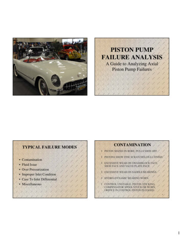
PISTON & ROD ORIENTATIONBY MIKE MAVRIGIANThis FEA (finite element analysis) view showseven stress forces at both major and minor thrustsides (note the dark dome areas), even thoughskirt areas differ in area. The offset location ofthe wrist pin aids in balancing-out the pivot point.(Courtesy JE)the piston weight to be slightly reducedby featuring a small footprint on theopposite/minor thrust side where theforce is less. During the power stroke,when the piston changes direction at topdead center, combustion pressure pushesthe piston down, and at the same timepushes the thrust side of the skirt towardsthe cylinder wall.Citing JE Pistons’ “asymmetric”design as an example, in their FSR(forged side relief) line, a wider skirt areais featured on the major thrust side, andthe pin bosses are relieved at the outboardsides to allow the use of a shorter (andlighter) wrist pin.The asymmetric piston design conceptwas initially developed years ago forspecific racing applications. While itdidn’t get much OE backing then, there isrenewed interest in it now and its use hastrickled down to street applications, withthe GM LS platform as a good example.An anti-friction coatingon the skirts aids in oilretention and providesadditional frictionreduction especiallyduring cold starts.While this canmore prominentlybenefit the majorthrust skirt,applying thecoating to bothmajor and minorskirts provides alubricity “back-up.”54OCT-DEC 2016 engine professionalFEA takes a snap shot of the piston’s stress levelsat the worst case scenario and differ greatlyfrom an engine that’s at part throttle. The imagerepresents a stress level plot. The high stressareas are shown in red in accordance with thechart on the right. This is a simulation of stressunder firing. (Courtesy JE)Another benefit to the asymmetricapproach with regard to skirt mass andprofile is increased piston ring sealingand ring stability. Basically, the dedicatedmajor and minor thrust skirt designcoupled with a slightly offset wrist pindirectly addresses ring performance inaddition to reduced wall friction.Offset pinAsymmetric pistons will also feature anoffset wrist pin, with the pin centerlinebiased from zero towards the majorthrust side by 0.020”. This slightoffset tends to balance the piston toaccommodate the difference in skirt massand to compensate for and alter the effectof rod angle, transferring a bit of forceaway from the major thrust side.Again citing JE’s development in thisarea, the asymmetric design allows theuse of shorter, stiffer and lighter wristThe stress of the piston under major stress.(Courtesy JE)pins. According to JE, a typical weightsavings is in the 10 gram range.NOTE: The contact pressure FEAimages show contact pressure specificallybetween the skirt panel and the bore. It’simportant to analyze both skirt profileson an asymmetrical piston design eventhough the minor thrust experiences amuch lower amount of pressure. On asymmetrical design, typically only themajor thrust is analyzed. Stress imagesshow how the stre
cylinder bore is slightly offset from the fore/aft intended location of the rod bearing radial centerline. Depending on the specific engine deign, the rod may feature an offset of as much as 0.100” or more. If in doubt, during test fitting, verify that the small end of the rod is