Transcription
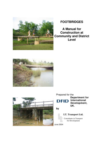
FOOTBRIDGESA Manual forConstruction atCommunity and DistrictLevelPrepared for theDepartment forInternationalDevelopment,UK.byI.T. Transport Ltd.Consultants in Transportfor DevelopmentJune 2004
CONTENTS PAGEPage NoACKNOWLEDGEMENTSABBREVIATIONS AND GLOSSARY OF TERMS(i)(iii)1.INTROUDCTION12.FOOTBRIDGE SPECIFICATIONS52.1 Planning2.1.12.1.22.1.3LocationLayout of the FootbridgeHeight of Deck2.2 Footbridge Users and Loading2.2.12.2.22.2.33.UsersDesign LoadsDesign CriteriaSELECTING A FOOTBRIDGE DESIGN3.1 Bamboo Bridges3.1.13.1.23.1.3Characteristics and ApplicationsAdvantages and DisadvantagesSources of Further Information3.2 Timber Log Footbridges3.2.13.2.23.2.3Characteristics and ApplicationsAdvantages and DisadvantagesSources of Further Information3.3 Sawn Timber Footbridges3.3.13.3.23.3.3Characteristics and ApplicationsAdvantages and DisadvantagesSources of Further Information3.4 Steel Footbridges3.4.13.4.23.4.3Characteristics and ApplicationsAdvantages and DisadvantagesSources of Further Information3.5 Reinforced Concrete (RCC) Bridges3.5.13.5.23.5.3Characteristics and ApplicationsAdvantages and DisadvantagesSources of Further 0313334343434
3.6 Suspension and Suspended Footbridges3.6.13.6.23.6.3Characteristics and ApplicationsAdvantages and DisadvantagesSources of Further Information3.7 Selection of Type of Footbridge3.7.13.7.23.7.33.7.44.Selection CriteriaComparison of Footbridge Types Against Selection CriteriaSelection of Type of FootbridgeRecommended Selection OptionsDESIGN OF TIMBER FOOTBRIDGES4.1 Introduction4.2 Bamboo Footbridges363636374141434647514.5 Maintenance of Timber .2.14.2.24.2.34.2.44.2.5General Design NotesBasic Construction of Bamboo FootbridgeImproved Bamboo FootbridgeLonger Span Bamboo FootbridgeMaintenance of Bamboo Footbridges4.3 Timber Log Footbridges4.3.14.3.24.3.34.3.4General Design NotesBasic Design of Timber Log FootbridgeMore Developed Timber Log FootbridgeTreatment of Timber4.4 Sawn-Timber Beam Footbridges4.4.14.4.24.4.3General Design NotesDesign of Sawn Timber Beam FootbridgeIncreasing the Span of Timber Stringer FootbridgesDESIGN OF STEEL TRUSS FOOTBRIDGE5.1 Introduction5.2 Design of Modular Steel Truss 5.2.95.2.105.2.11Design ConceptDetails of Side PanelsDetails of End PanelsDetails of Base PanelDetails of Joining Bracket and Drilling InstructionsAssembly and Welding of PanelsAssembly and Testing of FootbridgeBracing of Vertical PostsFixing of Footbridge on AbutmentsProtective TreatmentMaintenance5.3 Decking5.3.15.3.25.3.35.3.4Design of DeckingProtective Treatment of Timber DeckingMaintenance of DeckingAlternative Options Using Steel Plate798181848689919292929296969797979898
6.REINFORCED CONCRETE FOOTBRIDGES6.1 Introduction6.2 Design of Reinforced Concrete Footbridge6.2.16.2.27.Plain Slab DesignBeam Section DesignINSTALLATION OF FOOTBRIDGES7.1 Introduction7.2 Abutments7.2.17.2.27.2.37.2.47.2.5Selection of Type of AbutmentBuilding an Abutment on Existing RoadsTimber Sill AbutmentsRaised Timber AbutmentsConcrete and Masonry Abutments7.3 Piers7.3.17.3.27.3.37.3.4Timber PiersInstalling Timber PiersConcrete and Masonry PiersBearing Arrangements7.4 Erection of Footbridges7.4.17.4.27.4.3Erection Using Light Logs (beams)Construction of Temporary Structure/Scaffolding Across GapUse of Cable Way to Lift Stringers/Bridge into Position7.5 Organisation of Work7.5.17.5.27.5.3Planning and 30133133135136APPENDIX A:SITE SURVEY AND LAYOUT OF BRIDGEAPPENDIX B:CONSTRUCTION OF MODULAR STEEL TRUSSFOOTBRIDGEAPPENDIX C:CONSTRUCTION OF A FOOTBRIDGE USING ASCRAP TRUCK/BUS CHASSISAPPENDIX D:CONTACT DETAILS OF SOURCES OF FURTHERINFORMATION
ACKNOWLEDGEMENTSACKNOWLEDGEMENTSI T Transport Ltd gratefully acknowledges the significant contributions and help of thefollowing persons and organisations to the preparation of this manual.Bounmay Sengchanthala and Latsamay Aliyavongsing, Laos for: carrying out the casestudy on bamboo and timber bridges in LaosJoaquin Caraballo, Partner Lavial Consultants, South America for: review of draft manual;and contribution of much useful information and many photographs of footbridges in S.AmericaKen Frantz and Forrest Frantz of ‘Bridges to Prosperity’ for: the case-study on the steeltruss bridge installed by Bridges to Prosperity in Ethiopia; review of the draft manual; andcontribution of much useful data and photographs of footbridges.Ganesh Ghimire, Rural Infrastructure Specialist, Nepal for: organisation of the case-studyon timber and suspension footbridges in NepalGareth Gretton, Developing Technologies, Imperial College, London, for: finite elementanalysis and testing of the steel truss footbridgeSmart Gwedemula and colleagues in Malawi for: case-study on timber and RCC bridges inMalawi; review of the draft manual; and contribution of documentation from the VARBUprogramme in MalawiT. Hurmali, Flores Organisation for Rural Development, Indonesia for: carrying out thestudy on bamboo and timber bridges in IndonesiaDr. N. L. Joshi, Bridge Consultancy, Nepal for: review of the draft manual; and providinginformation on steel truss footbridges in NepalYogita Maini, Transportation Consultant, Department for International Development (DFID)for: comments on draft manualSamuel Orwa, R.M. Waruru and T.N. Shiteswa, Kisii Training Centre, Kenya for: review ofdraft manual; and providing information and photographs of a footbridge using a scrap truckchassis developed by the Training SchoolSusil Perera, Intermediate Technology Development Group (ITDG) Sri Lanka for:organisation and management of the testing of the modular steel truss footbridge in SriLanka; and review of the draft manualShuva Sharma, Scott Wilson Kirkpatrick, Nepal for: organisation of review of the draftmanual in Nepal and providing information on footbridgesGamelihle Sibanda, ILO-ASIST, Harare for: comments on the draft manualPage (i)
ACKNOWLEDGEMENTSTed Stubbersfield, Director of Outdoor Structures Australia for: review of the draft manual;and contribution of much useful information and comment on footbridges, particularlytimber bridgesTint Swe, Consultant for; review of the draft manualMs Jane Tourney, Consultant for: review of draft manual“This document is an output from a project funded by the UK Department forInternational Development (DFID) for the benefit of developing countries.The views expressed are not necessarily those of the DFID”.Page (ii)
ABBREVIATIONS AND GLOSSARY OF TERMSABBREVIATIONS AND GLOSSARY OF TERMSABBREVIATIONSADVDFLIMTKNNMTRCCUSDVARBUAnimal Drawn VehicleDesign Flood LevelIntermediate Means of TransportKilo-Newton (Approximately 100kg)Non-motorised TransportReinforced ConcreteUnited States DollarsVillage Access Roads and Bridge Unit (Malawi)GLOSSARY OF TERMSAbutmentsDead loadingDeckLive ructureSupports at each end of the footbridgeThe self-weight of the footbridge resting on the abutments and piersThe surface of the footbridge that users walk or ride onThe load imposed on the footbridge by usersIntermediate supports for the footbridge superstructure between theabutmentsBoards, usually timber, making up the box-work into which concreteis castBeams that support the deck. May be timber or steelAbutments and piers that provide the structure supporting thefootbridgeThe upper part of the footbridge structure comprising the deck, thestructure supporting the deck and safety railingsPage (iii)
ABBREVIATIONS AND GLOSSARY OF TERMSPage (iv)
1. INTRODUCTION1.INTRODUCTIONMuch rural travel takes place on local paths, tracks and village roads. These provideessential access to water, firewood, farm plots and the classified road network.Communities and/or local government are generally responsible for this network of pathsand tracks. One of the main problems they face is in providing effective water crossings.Particularly in the rainy season, the lack of an adequate crossing can prevent access toservices, or detours of many km or taking risks, especially by women and children, on anunsafe crossing.To provide safe and sustainable crossings, those providing technical assistance to localgovernment and communities need simple, easily applied guidelines on the selection andconstruction of effective water crossings. A manual, ‘Construction and Improvement ofFootpaths and Tracks’1, contains information on simple water crossings and an introductorychapter on footbridges but within the context of the manual it was not possible to providethe comprehensive guidelines needed for selecting and constructing footbridge designs forspecific applications.This follow-up manual deals specifically with the construction of simple but effectivefootbridges for spans up to about 20m and is targeted at local technical persons fromdistrict council staff, NGOs, local consultants etc. who are involved in providing technicalassistance to communities and small contractors in the construction of footbridges.Although the bridges covered in the manual are termed ‘footbridges’, the designs also allowfor use by livestock, IMT (Intermediate Means of Transport) such as oxcarts and theoccasional light motorised vehicle, for instance a pick-up.Before beginning the selection process it is necessary to confirm that a footbridge is thebest option for the water crossing. Other options are:-For shallow crossings, simple stepping stones may be adequateFor narrow crossings, a culvert may be a better optionFor wide crossings, a ferry may be the most practical optionFor low pedestrian traffic, a cable way may be the cheapest optionInstallation of a footbridge is usually a considerable undertaking, particularly forcommunities, and it is essential to make sure that it is really needed and is a top priorityand commitment for the communities involved.If it is decided that a footbridge is the best option the first step is to carry out a site survey todecide on the alignment of the footbridge and determine its specifications in terms of span(length between supports) and the traffic to be carried. The manual starts from this planningprocess and works through the process of selecting the most appropriate design offootbridge to meet the specifications. Detailed construction and installation guidelines arethen provided on a number of options that are considered the most appropriate. Theinformation is presented largely through pictorial sketches with brief notes of explanation.An understanding of engineering drawing practice is therefore not needed. Text is kept to aminimum.1Footpaths and Tracks – a field manual for their construction and improvement: produced by I.T. TransportLtd. for the UK Department for International Development (DFID), published by ILO/ASIST as RATP No.6,Geneva, 2002.Page 1
1. INTRODUCTIONA considerable volume of information already exists on footbridges but it is spread aroundand difficult to access. A major aim of the manual has therefore been to bring thisinformation together and present it in a form suitable for the target users. 5 case studieswere carried out in – Nepal, Laos and Indonesia in Asia and Malawi and Ethiopia in SubSaharan Africa – to collect data on specific types of footbridges. Library and Internetsearches were also carried out, yielding useful information from USA, Australia and the UK.Good information and manuals already exist on certain types of bridges such as cablebridges in Nepal. In these cases the reference sources are given and detailed designinformation is not included in the manual.Standard design data is included for the common types of footbridges found in rural areas –bamboo, timber log and sawn timber beam footbridges. These are suited to spans up to 10to 12m and longer if intermediate pier supports can be used. It is considered that the mostappropriate design for longer spans from 10 to 20 or 25m is a steel truss bridge. Standarddesigns for a version requiring full assembly on site are available from Nepal but nostandard designs were found for a modular type which is simpler to construct and assembleon site. A design of the latter type was therefore developed and field-tested in Sri Lanka.An important aspect of the field-test was to test and improve the presentation of data in themanual. Details of the construction and testing of the footbridge are available in a separatepublication.The content and layout of the manual are described in more detail below:Chapter 2:Footbridge SpecificationsThis chapter covers the planning stage to determine the specifications andlayout of the bridge, including the location and alignment of the bridge tospecify span, and identification of users to specify width and loading.The design loading and criteria used in the manual are derived andcompared with other footbridge standardsChapter 3:Selecting a Footbridge DesignThe range of design options for footbridges is outlined coveringcharacteristics, applications, advantages and disadvantages. Typicalexamples of each type are illustrated by photographs or drawings, showingbasic details of construction. Further sources of information are provided.The types of designs included are:--Bamboo bridgesTimber log and timber pole bridgesSawn timber, beam and truss types – glue-laminated designs arealso briefly described but are not considered appropriate for thismanualSteel beam and truss typesReinforced concrete footbridgesSuspended and Suspension bridgesThe criteria for selecting a footbridge type are discussed and the aboverange of options compared against these criteria. The types of footbridges tobe covered in detail in the manual are selected.Page 2
1. INTRODUCTIONChapter 4:Design of Timber FootbridgesDetailed designs and examples are given for 3 types:-Chapter 5:Bamboo footbridgesTimber log footbridgesSawn-timber beam bridgesDesign of Steel FootbridgeA standard design for a modular steel truss bridge for spans up to 20m isdescribed. Maintenance requirements are outlinedChapter 6:Design of Reinforced Concrete FootbridgesDesign details are given for a simple slab type of reinforced concrete (RCC)footbridge and the steps in construction are outlined.Chapter 7:Installation of FootbridgesDetails of the construction of abutments and piers are given, covering bothtimber and masonry types. Procedures for installing and fixing footbridges inposition are described.Appendix A:Site Survey and Layout of BridgeThis outlines the steps in carrying out the site survey with a questionnaire tocollect the required information for planning the bridge installation.Appendix B:Construction of Steel Truss FootbridgeDetailed step by step instructions are given for the manufacture of themodular steel truss footbridge that was described in Chapter 5.Appendix C:Construction of a Footbridge using a Scrap Chassis from a Truck or BusDetails are given of a footbridge constructed using a scrap truck chassis tospan the crossing and support the deck. It is based on information providedby the Kisii Training Centre in Kenya.Appendix D:Contact Details for Sources of Further InformationContact details are given for the sources of further information referred to inthe manualPage 3
1. INTRODUCTIONPage 4
2. FOOTBRIDGE SPECIFICATIONS2.FOOTBRIDGE SPECIFICATIONS2.1PLANNINGThis section summarises the factors that need to be considered in the planning of thedesign and installation of the footbridge.2.1.1LocationThe choice of location should try to minimise the cost of the footbridge and the workinvolved in installing it and maximise the benefits to the communities that will use it. Theselection process should consider the overall installation covering both the bridge and theapproach paths or tracks. The following factors should be considered: Use the shortest possible span (length) of the bridge taking into account the factorsbelow The footbridge should be on a straight section of the river or stream, away frombends where erosion can occur. Select a location with good foundation conditions for the abutment supports for thefootbridge The location should be as close as possible to any existing path or track alignment The location should provide good clearance against flooding and should minimisethe need for earthworks on the approaches to raise the level of the bridge The stream/river should have a well defined and stable flow path with little risk ofthis changing due to erosion of the banks The approaches should be across well-drained ground to minimise problems ofwater-logging and erosion The location should be as sheltered as possible to minimise wind problems The site should allow good access for materials and workers. It is helpful if there is a good local supply of materials that might be used in theconstruction such as sand and stones. The site should be agreed with the local communities2.1.2Layout of the FootbridgeA bridge is made up of 2 assemblies:1.The superstructure that provides the crossing for users, comprising the deck(carriageway surface), the structure which supports the deck such as beams ortrusses, and railings that provide safety for users. Various superstructure designs arepresented in Chapters 4, 5 and 6.Page 5
2. FOOTBRIDGE SPECIFICATIONS2.The substructure that supports the superstructure, comprising abutments that supportthe ends of the bridge and in some cases piers that provide intermediate supports forlonger span bridges. The design of substructures is presented in Chapter 7.The layout of the bridge is set primarily by the surrounding terrain and the height neededfor the superstructure. Three main factors need to be considered in deciding this:1.The clearance of the deck above the Design Flood Level (DFL) to provide acceptableaccess during flood periods (note that the approach paths/tracks will also need toprovide the same level of access) and to minimise potential damage to thesuperstructure from water and debris washed along in flood waters.2.The height of the superstructure needed to provide clearance for floating debris andany boats using the stream or river in normal operating conditions (it has to bedecided up to what water level it is reasonable to provide access for boats).3.The height on the banks where it is suitable to locate the bridge abutments in regardto appropriate soil conditions, minimising erosion from flood waters and minimisingthe difference in elevation between the bridge deck and approach paths/tracks (seeChapter 7).Figure 2.1 shows the basic layout of a footbridge. Simple, relatively low-cost footbridgesusing beam structures such as timber log or sawn timber are limited to spans of about 8 to10m by the available lengths of the beams. For longer spans an important initial decision tobe made is whether piers can be used for intermediate supports to allow beam structuresor whether it is cheaper to use more complex truss structures to avoid the use of piers. Themaximum span of truss type structures is 20 to 25m and above this a decision has to bemade whether to use piers or suspension type bridges that are suitable for longer spans.More guidelines on the selection of bridge types are given in Chapter 3 of the manual.2.1.3Height of DeckA Design Flood Level (DFL) needs to be defined. It may be an ‘average’ level (themaximum level that occurs in an ‘average’ year) or a higher level that occurs in 1 in ‘n’(10,20 etc.) years.It is suggested that the average upper level over a 5 year period is used and the height ofthe deck is set so that there is clearance under the superstructure to allow for some excessflooding and for debris carried in flood waters. Recommended clearances are: In fairly flat areas where flood waters can spread to limit rises in water level aminimum clearance of 1m is recommended. As the terrain becomes more hilly and banks are steeper so that flood waters aremore confined the clearance should be increased because of the greater variationin flood level. A clearance of up to 5m is recommended for hilly areas withstreams/rivers running in steep-sided gorges.The other critical factors of clearance for boats and the location of abutments also need tobe checked to see which criteria sets the minimum height of the deck.The average flood level can be checked by:Page 6
2. FOOTBRIDGE SPECIFICATIONSSafety handrail is advisableFor spans over 3mDeck supported bysuperstructure, suitablefor footbridge usersBeam typesuperstructureFlood LevelNormal LevelFill up to level of approachpath, track or roadPiers allow longer spans but bedneeds to be dry or stream divertedto allow excavation of footingsAbutments support ends ofsuperstructure. May be timber,masonry or concrete.Wingwalls may be neededfor protection(i) Beam Type SuperstructureTruss type superstructure suitable for longerspans than beams(ii) Truss Type SuperstructureNote:Careful consideration needs to be given for the location of abutments and piers to limit their impact onthe flow of water and to minimise the erosion they may cause. For example, a central pier is at the pointof highest water velocity and is best avoided where the water flow is high. An off-set pier is better if spansallow it. If not 2 piers should be considered.Figure 2.1: Layout of FootbridgePage 7
2. FOOTBRIDGE SPECIFICATIONS Site observations – signs of debris caught on vegetation, tide marks, sand/soildeposits Discussions with the local populationSetting out the level of the bridge deck is shown in Figure 2.2. Guidelines for survey of thesite and locating the positions of the abutments are given in Appendix A.Note:Increasing the height of the deck will usually lead to increasing its length and cost.However, it is likely to increase the security of the abutment against instability and erosionand reduce the risks of the deck being damaged or washed away by flood waters.It is therefore necessary to carefully balance the increased cost against the reduced risks.Minimising the risks will be increasingly important as the cost and predicted life of thefootbridge increase.2.2 FOOTBRIDGE USERS AND LOADING2.2.1 UsersThe users of the bridge and expected traffic levels must be clearly identified as these willdetermine the required deck width of the bridge and the ‘live’ loading on the bridge.Although termed “Footbridges”, in developing countries these bridges may be required toalso carry livestock, pack animals and a range of simple vehicles (Intermediate Means ofTransport, IMT) such as bicycles, handcarts, animal-drawn vehicles (ADVs), andmotorcycles. This need must be clearly defined.It may also be desirable for the bridge to carry an occasional light motorised vehicle suchas a pick-up. For instance if the bridge is on an access track to a village and there is noroad to the village.If the bridge is to allow access for ADVs then it will be difficult to exclude cars and pick-ups.However, the deck width should only just allow access for these vehicles and shouldprevent access of any heavier vehicles.Figure 2.3 shows recommended widths for paths and tracks for different types and levels oftraffic. Because of the relatively short lengths of footbridges and the significant costs ofconstruction it is considered that deck widths can be slightly less than those shown in thefigure. Two standard widths are therefore recommended in this manual: 1.4m for pedestrians, bicycles, livestock, pack animals, wheelbarrows and handcarts,and motorcycles 2.1m to also include ADVs and occasional light motorised vehiclesThese widths will only allow one-way access of some types of traffic and appropriatewarning notices should be put up at each end of the bridge. Also for heavier vehicles suchas ADVs, cars and pick-ups, only one vehicle should be allowed on the bridge at a time inorder to avoid the need to over-design the bridge for just a few users.Page 8
2. FOOTBRIDGE SPECIFICATIONSUse clinometer to setUp level reference lineMark onpostHHBase level of bridge deckClearance, see 2.1.3Height of maximum flood levelNote: Wherever possible the bridge should be perpendicular to the river/streamAbutmentSpanDeck LevelSlopelineAngle AoNote:It is important to consider the stability of the banks when choosing the locations for the abutmentsThe abutments should lie outside a slope line of Angle Ao which will depend on soil conditions.- For stable rock. A can be up to 60o- For firm soil A should not exceed 45o- For loose sand, gravel and soft soil A should not exceed 35oFigure 2.2: Level of Bridge DeckPage 9
2. FOOTBRIDGE SPECIFICATIONSStandard Widths for Different Paths and Tracks1.0m wide1.2m wideTwo-Way Footpath- pedestrians- low trafficTwo-Way Footpath- pedestrians- high traffic1.4m wide1.2m wideOne-Way Track- pedestrians- pack animals- low to medium trafficOne-Way Bicycle Track- bicycles- low traffic2.0m wide2.0m wide2.5m wideTwo-Way Bicycle Track- bicycles- high trafficTwo-Way Track- pedestrians- pack animals- high trafficMotorable Track- carts- 4WD vehicles- low traffic(passing places required)Guideline for level of traffic for walkers and bicycles:Low: less than 50/dayMedium: 50 to 500/dayStandard Widths of Footbridges Recommended in Manual1.4mTwo-Way: pedestriansOne-Way: livestockpack animalsbicyclesHigh: over 500/day2.1mTwo-Way: pedestrians, bicycleslivestockOne-Way: pack animalsanimal-drawn cartsLight motor vehiclesNote:Footpaths allow comfortable clearance. Because of their short lengthsfootbridges need provide only minimum clearance.Figure 2.3: Proposed Standard Widths for FootbridgesPage 10
2. FOOTBRIDGE SPECIFICATIONSSelection of width – this needs to be considered carefully. The potential loading on a 2.1mwide bridge is 50% greater than on a 1.4m wide bridge and therefore it has to be madesubstantially stronger, increasing cost in about the same proportion. If an ADV or motorvehicle is only expected to want to use the bridge occasionally, say 2 or 3 times per month,then the need for access has to be critically assessed with the local communities to makesure the extra cost is justified.Restriction of vehicle size – it is recommended that masonry columns are built at each ofthe bridge with an opening of 1.9m. These will allow access for a Landrover and mediumsize pick-up but prevent larger vehicles from damaging the bridge.2.2.2Design LoadsFootbridges have to be strong and rigid (without undue flexibility or deflection) to withstandthe following forms of loading:Vertical loading -(i)(ii)Dead loading from the weight of the bridge itself (snowloading is not usually considered for footbridges as it isunlikely to be significant when the bridge is being heavilyused).Live loading from the users of the bridgeThe vertical design load is the combination of dead load and the highest live loadanticipated from the users of the bridge. The dead load is the distributed weight of thesuperstructure including decking and can readily be evaluated. The highest live load ismore difficult to estimate and is discussed below.Side loading -(i)(ii)(iii)From wind pressureDue to users leaning on or bumping against the safety railingsDue to the possibility of debris carried by the river/streamimpacting against the bridge. Note: that it is only feasible todesign against relatively light impacts. If heavy impacts arepossible from larger objects in fast flowing water then thedeck clearance (2.1.3) should be increased to reduce the riskof impact and damage.Side loading to be considered in the design is wind loading acting on the exposed sidefaces of the bridge members and loads applied by users leaning on or bumping against thesafety rails and support posts. Significant impacts from debris will not occur if there isadequate clearance below the bridge.Design standards for footbridges consider wind velocities up to 140 to 160 km/hr. Thisimposes a uniform pressure on the exposed side faces of the bridge members of 130 to140kg/m2. The upper figure is used in the designs in this manual. Since there is unlikely tobe traffic on the bridge in these high winds, the wind loading is considered separately fromvertical live loading.Page 11
2. FOOTBRIDGE SPECIFICATIONSLive loads – two aspects of live loading need to be considered:(i)The point load applied to the bridge deck by a person’s or animal’s foot or the wheelof a vehicle, to check the strength of the decking(ii)The load transferred from the decking to the structural members of thesuperstructure which then transfer it to the bridge supports. These loads will act asa series of short distributed loads or as a continuous distributed load spread alongthe longitudinal members that support the decking.The most critical live loads assumed for users of footbridges are shown in Table 2.1. Liveloading by other types of users is considered to be less than these cases as explainedbelow:--Bicycles and motorcycles – the point loads will be less than those assumed forlivestock and because of the space they take up the load per unit area will be lessthan for pedestriansPack animals – these are assumed to be donkeys, mules, horses or camels. Themaximum loading is assumed to be similar to that of livestock which may includeoxen.The design live loads used in this manual are summarised at the bottom of Table 2.1. It isconsidered that the point load of 500kg (5kN) and distributed load of 400kg/m2 providean adequate margin of safety for all normal users of footbridges. The live loadspecifications for the two bridge widths are summarised in Table 2.2. Table 2.3 comparesthese specifications with those from other manuals.2.2.3Design CriteriaBridge design standards specify the following design criteria which need to be consideredto ensure that footbridges are safe and convenient for anticipated users.1.Strength:the bridge members need to be strong enough to withstand the liveand dead loads identified above with an adequate margin of safety toallow for uncertainties in loading, material proper
4.3.2 Basic Design of Timber Log Footbridge 62 4.3.3 More Developed Timber Log Footbridge 68 4.3.4 Treatment of Timber 68 4.4 Sawn-Timber Beam Footbridges 70 4.4.1 General Design Notes 70 4.4.2 Design of Sawn Timber Beam Footbridge 71 4.4.3 Increasing the Span of Timber Stringer Footbridges 74