Transcription
PREFACEThis Timber Pile Design and Construction Manual has been developed by the SouthernPressure Treaters' Association as its official recommendation for Timber Piling Designand Construction.The data in this publication has been prepared in accordance with recognizedengineering principles and is based on available technical data. The information in thismanual should not be used or relied upon for a specific application without competentprofessional examination and verification of its accuracy, suitability, and applicability bya licensed professional engineer.By publication of this manual, SPTA intends no representation or warranty, expressedor implied, that the information in the manual is suitable for any specific application oris free from infringement of any patent or copyright. Any user of this informationassumes all risk and liability arising from such use.The manual was developed to assist design engineers with the design of timber piling.Manual Author: James G. Collin, Ph.D., P.E., The Collin Group, Ltd.The manual was reviewed by the SPTA Timber Pile Manual Technical Committee.Edited and Revised 2016 by Edward D. Entsminger, M.S., Rubin Shmulsky, Ph.D., andJeanie McNeel, Department of Sustainable Bioproducts, Mississippi State University.SPTA Timber Pile Manual Technical CommitteeKevin RagonGrady BraffordTom O’MalleyRandy KellyMorgan WrightSpecial thanks is given to the following for their advice on the manual.Ryan R. Berg, P.E., Ryan R. Berg & AssociatesMartin Rollins, P.E., H. M. Rollins Company, Inc.Future changes to this manual will be posted on the following website. www.Copyright Southern Pressure Treaters' Association 2002All rights reserved. Printed in the USA. Updated 2016.Western Wood Preservers InstitutePile Driving Contractors AssociationDepartment of Sustainable BioproductsDeep Foundations Institute
Timber Pile Design and Construction ManualTable of Contents1.0Introduction1.1 Scope of Manual1.2 Background1.3 Seismic Design Considerations1.4 Organization of Manual2.0Foundation Design Procedure2.1 Design of Foundations2.2 Foundation Design Process3.0Timber Pile Properties3.1 Introduction3.2 Allowable Stress Design3.3 Tabulation of Allowable Stress and Pile Capacity3.3.1 Pile Capacity3.4 Pile Size Specifications3.5 Working Strength Based on Small Clear Wood Specimens3.5.1 Axial Compressive Stress3.5.2 Extreme Fiber Bending Stress3.5.3 Compressive Stress Perpendicular to the Grain3.5.4 Shear Stress Perpendicular to the Grain3.5.5 Modulus of Elasticity3.6 Allowable Stress3.6.1 Load Duration3.6.2 Temperature3.6.3 Pressure Treatment3.6.4 Size3.6.5 Load Sharing3.6.6 Allowable Stress3.7 Preservative Process3.7.1 Creosote3.7.2 Chromated Copper Arsenate (CCA)3.7.2.1 CCA Industrial Uses3.7.3 Ammoniacal Copper Zinc Arsenate (ACZA)3.7.4 CCA and ACZA3.7.5 Preservative Retention3.7.6 Pentachlorophenol and Copper Naphthenate3.8Durability Considerations3.9Environmental Considerations4.0Static Analysis Design Procedures4.1 Introduction4.2 Soil/Pile Interaction4.2.1 Load Transfer4.3 Factors of Safety
4.44.54.65.0Engineering News FormulaWave Equation AnalysisDynamic MonitoringDesign of Single Piles5.1 Introduction5.2 Meyerhof Method for Piles in Cohesionless Soils5.3 Nordlund Method for Piles in Cohesionless Soils5.4 Alpha ( ) Method for Piles in Cohesive Soils5.5 Effective Stress Method for Piles in Cohesionless and CohesiveSoils5.6 Nottingham and Schmertmann Method5.7 Uplift Capacity of Single Piles6.0Design of Pile Groups6.1 Introduction6.2 Axial Capacity of Pile Groups in Cohesionless Soils6.3 Axial Capacity of Pile Groups in Cohesive Soils6.4 Settlement of Pile Groups in Cohesionless Soils6.5 Settlement of Pile Groups in Cohesive Soils7.0Lateral Design Considerations7.1 Introduction7.2 Broms’ Method8.0Pile Installation8.1 Introduction8.2 Pile Driving Equipment8.2.1 Leads8.2.2 Pile Hammers8.2.3 Helmet8.3 Hammer Size Selection8.4 Pile Accessories8.5 Pile Cutoffs9.0Pile Load Testing9.1 Introduction9.2 Axial Compression Static Load Test9.2.1 Interpretation of Load Test10.0 Quality Assurance During Pile Driving10.1 Introduction10.2 Timber Pile Quality Requirements10.3 Material Certification10.4 Pile Driving Equipment and Pile Installation
11.0 Specifications11.1 Introduction11.2 Material Specification12.0 Geotechnical Considerations12.1 Introduction12.2 Planning Site Investigation12.2.1 Desk Study – Available Existing Data12.2.2 Field Reconnaissance12.3 Guidelines for Minimum Subsurface Exploration Program12.4 Methods of Subsurface Exploration12.4.1 Hollow-Stem Augers12.4.2 Rotary Wash Borings12.4.3 Test (Exploration) Pit Excavation12.5 Soil and Rock Sampling12.5.1 Soil Samplers12.6 Groundwater Conditions12.7 Subsurface Profile Development12.8 In-Situ Soil Testing12.8.1 Cone Penetration Test (CPT)12.8.2 Vane Shear Test12.9 Laboratory Soil Testing12.9.1 Index Tests12.9.2 Shear Strength Tests12.9.3 Consolidation Tests12.10 Laboratory Testing for Pile Driveability DeterminationReferencesAppendix ADesign Example ProblemsProblem 1Meyerhof MethodNordlund MethodProblem 2Alpha ( ) MethodProblem 3Effective Stress Method
CHAPTER 1.0INTRODUCTION1.1 SCOPE OF MANUALAll objects and structures transfer their load either directly or indirectly to the earth. Thecapacity of the earth to support such loads depends on the strength and stability of thesupporting soil or rock materials. Not all foundation materials possess the requiredcharacteristics to carry imposed loads or to resist natural or man-made forces without resultingin damage to the structures they support. Consequently, the engineer is faced with the task ofdesigning foundations to distribute high-intensity loads in a manner that can be supported byexisting natural subgrade materials, and/or modifying those natural materials.There are three basic approaches to achieving proper support of structures. These are: a)distribution of structural loads to foundations, such that the intensity of the loads transferred willnot cause shear failure or objectionable settlement of the structure; b) modification of thefoundation soil (i.e., soil improvement); or c) a combination of "a" and "b" above.There are two general types of foundations for distributing applied structural loads to theground: shallow foundations, and deep foundations. Shallow foundations principally distributestructural loads over large areas of near-surface soil to lower the intensity of the applied loads tolevels tolerable for the foundation soils. The analysis and design of shallow foundations is notdiscussed in this manual. Deep foundations distribute loads to deeper, more competent soils orto rock, by means of skin-friction, end bearing, or a combination of both. This manual is devotedto the discussion of the structural and geotechnical aspects of timber pile foundation design.This design manual follows the design methodology presented in the Federal HighwayAdministration’s Design and Construction of Driven Pile Foundations (FHWA-NHI-05-042 and043). The information from this FHWA document has been condensed to focus solely on timberpiles and has been supplemented to provide additional guidance with respect to the selectionof timber pile structural properties required for design.1.2 BACKGROUNDTimber piles have successfully supported structures for more than 6,000 years. Over the years,the methods that man has employed to extend the life of timber piling have evolved to the pointthat timber piles will last for over 100 years. Ancient civilizations used various animal, vegetable,and mineral oils to preserve timber. In Roman times, timbers were smeared with cedar oils andpitch, then charred to extend their service life. Roman roads built on treated piles were still ingood condition 1,900 years later. A building built in Venice, Italy in 900 A.D. was rebuilt around1900 C.E. on the same 1,000-year-old piles.The modern age of wood preserving began in England in 1832. Pressure injection of coal-tarcreosote into wood began in 1838. Following the successful use of pressure treated railroadties, U.S. railroads started treating foundation piles in the early 1880’s.Timber Pile Design and Construction ManualPage 1
Since then, pressure treatment has been recognized as a process that protects wood byextending its life indefinitely. This is why building codes require wood for certain uses to be“treated” and why codes explicitly define “treated” as pressure treated.In recent years, extensive load tests have been performed on pressure treated timber foundationpiles. Design loads as high as 75 tons have been specified and ultimate loads as high as 235tons; have been carried by timber piles. There are wooden piles loaded to 60 tons each underbridges spanning the Thames River in London and 100-ton timber piles in bridges spanning theRiver Seine in Paris.Today woodpiles are a mainstay of foundation designers. Woodpiles are being routinely usedin all kinds of structures, including marines structures, manufacturing plants, processingfacilities, commercial buildings, and highway bridges. For example, thousands of pressuretreated woodp i l e s were used for the foundation of new facilities at JFK Airport in New York,and at Dulles International Airport in Northern Virginia. The city of New Orleans, Louisiana isbuilt on timber piles. Residential buildings, commercial buildings and the Superdome as well aspaved highways in New Orleans are supported on timber piles. New Orleans, however, is notalone in its use of timber piles to support highways. The highest ever-recorded design load fortimber piles in U.S. highway construction is a 1,000-foot long viaduct, supported by timber piles,which have a 75-ton design load on Interstate 80 near Winnemucca, Nevada. Timber piles aremost common and economical for loads in the range of 5 to 40 tons. We do not encourageoverstressing the pile.Wood is among the most commonly available, cost effective, versatile, and environmentallyfriendly building materials. In an age where carbon footprints, environmental stewardship, longterm life cycle cost, and embodied energy are critical in the decision making associated with newindustrial projects, timber is increasingly the design material of choice.1.3 SEISMIC DESIGN CONSIDERATIONSThe scope of this manual does not include seismic design considerations. There is on-goingresearch on Performance-Based Seismic Design funded by the Federal Emergency ManagementAgency (FEMA). A separate bulletin is planned on Seismic Design Considerations for timberpiling in the future.1.4 ORGANIZATION OF MANUALThis manual is intended to be a stand-alone document and is geared towards providing thepracticing structural and geotechnical engineer with a thorough understanding of the design andconstruction of timber pile foundations. The organization of the manual is presented below.Chapter 2 provides an overview of the design process for a timber pile foundation.Chapter 3 covers the selection of the strength properties of timber piles and considerations withrespect to pile durability.Chapter 4 gives an overview of the static design process for timber piles.Chapter 5 presents five design methods to determine the static capacity of single piles in bothcohesive and cohesionless soils.Chapter 6 covers the design of timber pile groups.Timber Pile Design and Construction ManualPage 2
Chapter 7 discusses design considerations for lateral loading applications.Chapter 8 discusses pile installation considerations.Chapter 9 covers static and pile load testing.Chapter 10 deals with quality assurance and quality control during timber pile installation.Chapter 11 provides a model specification for timber pile projects.Chapter 12 reviews the geotechnical considerations that are important in defining the siteconditions (i.e., subsurface exploration program) and provide the design engineer with thenecessary information to perform the foundation design with respect to the subsurface soils.This manual does not cover seismic/dynamic analysis. For information on this subject, thereaders are referred to the Federal Highway Administration’s Design and Construction of DrivenPile Foundations (FHWA-NHI-05-042 and 043).Timber Pile Design and Construction ManualPage 3
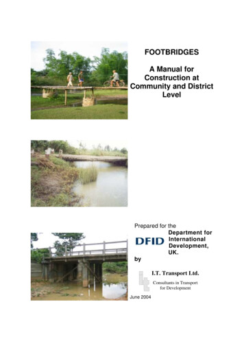
CHAPTER 2.0FOUNDATION DESIGN PROCEDURE2.1 DESIGN OF FOUNDATIONSFoundations are often classified as shallow or deep foundations, depending on the depth of theload-transfer member below the superstructure. Thus, a deep, as compared with a shallowfoundation becomes a relative term. A shallow foundation, as defined in this manual, is one inwhich the depth to the bottom of the footing is less than or equal to four times the smallestdimension of the footing. A shallow foundation also has lower bearing capacity.The foundation engineer must have a thorough understanding of the foundation loads,subsurface conditions, including soil/rock properties and behavior, foundation performancecriteria, and current practices in foundation design and construction in the area where the workis to be done to arrive at the optimum foundation solution. When designing foundations, it isessential to systematically consider the various foundation types and to select the optimumalternative based on the superstructure requirements, subsurface conditions, and costs.2.2 FOUNDATION DESIGN PROCESSThe timber pile foundation design-construction process is outlined in the flow chart in Figure 2-1.This flow chart will be discussed block by block, using the numbers in the blocks as a reference,and will serve to guide the designer through all of the tasks that should be considered (afterFHWA-NHI-05-042 and 043).Block 1: Assemble Information Regarding Proposed StructureThe first step in the process is to determine the general structure requirements. The followingquestions should be asked and answered during this phase of the design process: Is the projecta new commercial office building, a residential building, a new bridge, a replacement bridge, aretaining wall, a noise wall, a sign, etc.? Will the project be constructed in phases or all at once?What is the general structure layout? Is the structure subjected to any special design eventssuch as seismic, scour, debris, etc.? If there are special design events, the design requirementsfor the event should be reviewed at this stage so that these considerations can be factored intothe site investigation. What are the approximate foundation loads? Are there deformation ordeflection limitations beyond the usual requirements? This process has been improved andexpanded upon in the FHWA-NHI-05-042 and 043).Block 2: Obtain General Site GeologyA great deal may be learned about the foundation requirements with even a very generalunderstanding of the site geology. For small structures, this may involve only a very superficialinvestigation such as a visit to the site. The foundation design for very large structures mayrequire extensive geologic studies.Timber Pile Design and Construction ManualPage 4
Block 3: Collect Foundation Experience from the AreaFrequently there is information available on foundations that have been constructed in the area.This information can be of assistance in avoiding problems. Both subsurface explorationinformation and foundation construction experience should be sought prior to selecting thefoundation type.Block 4: Develop and Execute Subsurface Exploration ProgramBased on the information obtained in Blocks 1-3, it is possible to make decisions regarding thenecessary information that must be obtained at the site. The program must meet the needs ofthe design problem that is to be solved at a cost consistent with the size of the structure. Forexample, if it is obvious that shallow foundations are feasible, then shallow borings areacceptable; vice versa if deep foundations are obvious, then multiple deep borings. Thesubsurface exploration program, as well as the appropriate soil laboratory-testing program, mustbe selected. The results of the exploration and testing programs are used to prepare asubsurface profile and identify critical cross-sections.Block 5: Evaluate Information and Select Foundation SystemThe information in Blocks 1-4 must be evaluated and a foundation system selected. The firstquestion to be decided is whether a shallow or a deep foundation is required. This question willbe answered based primarily on the strength and compressibility of the site soils, the proposedloading conditions and the project performance criteria. If settlement is not a problem for thestructure, then a shallow foundation will typically be the most economical solution. Groundimprovement techniques in conjunction with shallow foundations should be evaluated when ashallow foundation does not meet the project requirements. If the structure performance criteriacannot be met by a shallow foundation, a deep foundation should be used.Refined foundation loading information and performance criteria should be established at thistime. In Block 1, this issue was considered. At this stage of the design effort, a better definitionof the design foundation loads and performance criteria are typically available. They should beincluded in the design process. The geotechnical engineer should obtain a completely definedand set of foundation loads, and performance requirements in order to proceed through thefoundation design.Block 6: Deep FoundationAt this stage, the designer must decide between a deep foundation system and either a shallowfoundation with soil improvement or a shallow foundation. The decision on foundation typeshould be based on performance and economics.Block 7: Driven PilesOnce a deep foundation has been selected, the designer must decide to use either driven pilesor other deep foundation systems (i.e., drilled shafts, auger cast piles, etc.). The question thatshould be answered in deciding between driven piles and other deep foundation systems iswhich system will perform as desired for the least cost. In addition to performance and cost,constructability should be considered, including accessibility, etc.Timber Pile Design and Construction ManualPage 5
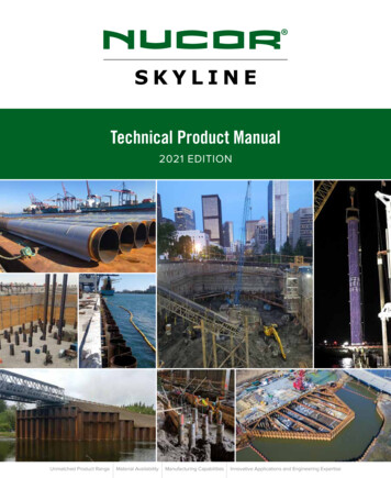
Block 8: Select Driven Pile TypeThe pile type should be selected consistent with the applied load per pile. The general magnitudeof the applied load is known from the information obtained in blocks 1-5. A large number ofcombinations of pile capacities and pile types can satisfy the design requirements. Theselection of pile type should consider both the structural capacity of a pile and the realisticgeotechnical capacity of the pile type for the soil conditions at the site, the cost of alternativepiles, and the capability of available construction contractors to drive the selected pile. Timberpiles are economical piles that should be considered when anticipated pile loads are between10 and 80 kips and when anticipated pile lengths are between 20 – 70 feet. Table 2-1presents various types of driven piles their advantages and disadvantages, and what conditionsare most favorable for their use.Block 9: Calculate Pile Length and CapacityFor timber piles, perform a static analysis to estimate the length necessary to provide therequired capacity (i.e., compression, uplift, and lateral load). It may be necessary to increase thenumber of piles to satisfy the structural requirements. The allowable stresses should also beinvestigated in this stage for structural purposes. Keep in mind that uplift loads are relativelysmall for timber piles.Block 10: Evaluate DriveabilityThe static design completed in block 9 addresses the structural/geotechnical capacity of thepile. It is also important to assess the driveability of the selected pile to assure that the requiredcapacity and penetration depth may be achieved at a reasonable driving resistance. The finaldriveability analysis cannot be completed until the pile hammer has been selected (this willdepend on the contractor selected for the project). The geotechnical engineer should conductpreliminary analyses based on local knowledge of typical or commonly available hammers aspart of the constructability review. Pile driveability is best evaluated by wave equation analysismodeling of the selected hammer, pile, and soil profile.Block 11: Satisfactory DesignAt this point, the computations for the design are complete.Block 12:Prepare Plans and SpecificationsThe design is, in fact, not complete until the plans and specifications are prepared. It is importantthat all of the tolerances and quality control procedures are clearly defined to avoid claims afterconstruction is underway.Timber Pile Design and Construction ManualPage 6
Foundation Design Process1) Obtain structural information, project details, and site characteristics2) Obtain general site geology3) Collect foundation experience from the area4) Develop and execute subsurface exploration program5) Evaluate information and select foundation systemGround modification forshallow foundation: Notcovered in this manual6) Deep foundationShallow foundation: Notcovered in this manual7) Driven pilesOther deep foundationtypes: Not covered in thismanual8) Select timber pileOther Driven Piles:Not covered in thisManual9) Calculate pile capacity and length10) Evaluate driveability(If No)11) Verify that design is satisfactory(If Yes)12) Prepare plans and specificationsFigure 2-1: Flow chart of timber pile design processTimber Pile Design and Construction ManualPage 7
Table 2-1Pile TypeTimberSteel H-PipeSteel RoundPipeTypical Length (ft.)20-75 (D-fir to 125)20-10030-120Typical AxialDesign Loads (kips)35-80100-500200-600Low CostRenewable ResourceEasy to handleEasy to drivePile length variations easilyaccounted for Tapered section provideshigher resistance ingranular soils than uniformpiles Use as friction or endbearing pile Easy to splice High capacity Smalldisplacement Easy to drive Good forpotentialobstacles Open endedgood againstobstructions High loadcapacity Closed endedpipes Vulnerable tocorrosion Not recommended forfriction pile Displacementfor closed endpipe Open endednot recommended asfriction pile AdvantagesDisadvantages Difficult to splice Low axial capacity Low uplift capacityTimber Pile Design and Construction ManualPre-Cast PreStressedConcrete30-45 (Precast)45-120 (Prestressed)100-300 High loadcapacity Corrosionresistanceobtainable High breakagerate Vulnerable tohandlingdamage High initial costCast-in PlaceConcrete MandrelDriven ShellCast-in-PlaceConcrete ShellsDriven WithoutMandrel10-12015-80100-300100-300 Initial economy Tapered sectionsprovide higherresistance ingranular soilsthan uniformpiles Can be inspectedafter driving Can beredriven Shell noteasilydamaged Difficult to spliceafter concreting Thin shellvulnerableduring driving Considerabledisplacement Difficult tosplice afterconcretingPage 8
CHAPTER 3.0TIMBER PILE PROPERTIES3.1 INTRODUCTIONThe design of timber pile foundations requires a firm understanding of the mechanical propertiesof the timber pile. There are generally two species of timber used for the manufacture of timberpiles: Douglas Fir and Southern Yellow Pine. Other species such as Caribbean Pine, LodgepolePine, Red Oak, Red Pine, and Hardwoods are also used on occasion.ASTM D 25 Standard Specification for Round Timber Piles establishes physical properties andmanufacturing requirements and ASTM D 2899 Standard Practice for Establishing Stresses forRound Timber Piles provides the procedures for developing timber-piling stresses from smallclear s p e c i m e n s . The strength properties are derived from clear wood strength of smallspecimens tested in accordance with ASTM D 2555 Standard Test Method for EstablishingClear Wood Strength Values.Research (Bodig and Arnette, 2000) on full-scale strength testing has been conducted onapproximately 100 Southern Yellow Pine piles and 100 Douglas Fir piles. This research hasdemonstrated that currently used allowable design stresses are conservative. Additional researchon wood pole design property verification was performed in 2012-2013 in conjunction with theSouthern Pressure Treaters’ Association. This 2016 Manual contains updated axial designvalues for timber piles and updated capacity tables.3.2 ALLOWABLE STRESS DESIGNThe selection of material properties for piles must consider both static and dynamic stresses. Apile must be able to withstand the dynamic stresses induced in the pile during the drivingprocess, as well as the static stresses that the pile is subjected to in service.The allowable stresses for timber piles published in this manual are based on the AmericanWood Council (AWC) publication, Manual for Engineered Wood Construction – Allowable StressDesign, Supplement Timber Poles and Piles and procedures outlined in the ASTM standardsreferenced above and the AWC’s National Design Specification (NDS) for wood. Allowablestresses and pile capacity are tabulated in section 3.3 and maximum butt and tip dimensionsversus pile length are presented in section 3.4. Section 3.5 reviews the procedures to determinethe allowable stresses for timber piles from small clear wood specimens. Section 3.6 provides ananalytical method for reusing typical allowable stresses using reduction factors to account forload duration, temperature, pressure treatment, etc.3.3 TABULATION OF ALLOWABLE STRESS AND PILE CAPACITYTable 3-1 provides recognized allowable stresses for timber piles, as published by the AmericanWood Council, in the NDS. The values provided in table 3-1 are applicable for pile groups, withwet exposures, at normal temperature range (i.e., 100 F), and with a “normal” load durationfactor of 1. The tabulated values are given for piles treated with a preservative using a steamconditioning or Boultonizing processes. For piles that are air dried or kiln-dried prior to treatingstresses may be increased by 11% to 18% (see section 3.6).Timber Pile Design and Construction ManualPage 9
Table 3-1Allowable Stress Values for Treated Round Timber Piles Graded in Accordance withASTM D25AxialCompression(Fc) (psi)Bending(Fb) (psi)ShearPerpendicular tothe Grain (Fv) (psi)CompressionPerpendicular to theGrain (Fc ) (psi)Modulus ofElasticity ,00011501700802701,000,000Red Oak3110024501353501,250,000Red glasFir2LodgepolePine1.2.3.4.5.Southern Pine design values apply to Loblolly, Longleaf, Shortleaf, and Slash Pines.Pacific Coast Douglas Fir design values apply to this species as defined in ASTM D 1760.Red Oak design values apply to Northern and Southern Red Oak.Red Pine design values apply to Red Pine grown in the United States.Data in Table above was taken from 2012 National Design Specifications.3.3.1 Pile CapacityTable 3-2 provides compression strength parallel-to-the-grain for Southern Pine and Douglas Firas a function of the specified pile tip circumference (ASTM D25). The allowable values areonly applicable when the pile tip circumference is specified in accordance with ASTM D25. Thevalues presented in Table 3-2 do not consider buckling capacity of timber piles.The tip of the pile represents the smallest circumference and lowest strength section of a pile.Additional capacity may be computed at other locations in the pile by considering load transfer, theincreased cross-sectional area away from the tip using linear taper and specified butt circumference.Table 3-2 for allowable design capacities is based on the following conditions: Timber piles meet ASTM D25In-service temperature range 100 FWet service conditionsTimber piles have had preservative treatmentCompression members fully laterally supported (fully embedded in soil)Piles in a cluster (pile groups)Critical location for compression parallel to the grain is the tip of the pile.When these conditions do not occur, the pile capacity should be adjusted using the adjustmentfactors presented in Table 3-10.3.4 PILE SIZE SPECIFICATIONSThe natural taper of timber piles is a factor in the design formula. The natural taper of Southernpine is approximately 0.1 inch per foot throughout the length. Douglas Fir has a smaller taperwithin 20 feet of the butt. The result is often a smaller tip for a given butt size in Douglas Firand other western species.Timber Pile Design and Construction ManualPage 10
Table 3-3 provides specified butt circumferences with corresponding minimum tip sizes forSouthern pine. Table 3-4 provide specified tip circumferences with corresponding minimum buttcircumferences for Southern Pine. The corresponding tables for Douglas Fir and other westernspecies are in Tables 3-5 and 3-6. Tables 3-7 through 3-9 provide additional dimensional informationfor various pile classes/types.Table 3-2Allowable Pile Capacity in Compression (kips)TimberSpeciesAllowable Pile Capacity in Compression (kips)Pile Tip Diameter89 (inches)1011712Southern Pine48638098119141Douglas Fir506583102124147Table 3-3 Southern Pine Foundation Piling – Specified Butt Circumferences withCorresponding Minimum Tip Circumferences A,B,C,D,E (from ASTM D25 - Table X1.3)[Approximate Tip Diameters in Brackets]Required Minimum Circumference, in., 3-ft.from buttsLength (ft.)44 [14]47 [15]50 [16]57 [18]31 [9.9]34 [10.8]37 [11.8]40 [12.7]47 [15.0]30 [9.5]33 [10.5]36 [11.439 [12.4]46 [14.6]26 [8.3]29 [9.2]32 [10.2]35 [11.1]38 [12.2]45 [14.3]22 [7.0]25 [8.0]28 [8.9]31 [9.9]34 [10.8]37 [11.8]44 [14.0]21 [6.7]24 [7.6]27 [8.6]30 [9.5]33 [10.5]36 [11.443 [13.7]20 [6.4]23 [7.3]26 [8.3]29 [9.2]32 [10.2]35 [11.1]42 [13.4]19 [6.0]22 [7.0]25 [8.0]28 [8.9]31 [9.9]34 [10.8]41 [13.0]21 [6.7]24 [7.6]27 [8.6]30 [9.5]33 [10.5]40 [12.7]20 [6.4]23 [7.3]26 [8.3]29 [9.2]32 [10.2]39 [12.4]6519 [6.0]22 [7.0]25 [8.0]28 [8.9]31 [9.9]38 [12.2]7018 [5.7]21 [6.7]24 [7.6]27 [8.6]30 [9.5]37 [11.8]7520 [6.4]23 [7.3]26 [8.3]29 [9.2]36 [11.4808519 [6.0]22 [7.0]25 [8.0]28 [8.9]35 [11.1]18 [5.7]21 [6.7]24 [7.6]27 [8.6]34 [10.8]20253035404550556022 [7]25 [8]28 [9]31 [10]35 [11]38 [12]16
The manual was developed to assist design engineers with the design of timber piling. Manual Author: James G. Collin, Ph.D., P.E., The Collin Group, Ltd. The manual was reviewed by the SPTA Timber Pile Manual Technical Committee. Edited and Revised 2016
![Pile Foundation Design[1] - ITD](/img/29/pilefoundationdesign.jpg)