Transcription
BASIC TIMBER DESIGN CONCEPTS FOR BRIDGES5.1 INTRODUCTIONFor thousands of years, timber bridges and other timber structures werebuilt primarily by trial and error and rule of thumb. Designs were based onpast experience, and little concern was given to efficient material usage oreconomy. As the complexity of structures increased, more attention wasfocused on the importance of accurate engineering methods. Research wasundertaken to develop design criteria for wood with the same level ofaccuracy and reliability available for other engineering materials. As aresult, developments in timber design have advanced substantially in thiscentury. Although wood is orthotropic and differs in many respects fromother materials, wood structures are designed using many of the sameequations of mechanics developed for isotropic materials. Variations inmaterial properties from growth characteristics, manufacturing, and useconditions are compensated for by material grading and stress adjustmentsapplied in the design process. Timber design may seem confusing at first,but with experience it is no more difficult than design with other materials.This chapter provides an overview of basic design concepts for sawnlumber and glulam used in bridge design. It includes specification require ments and methods for designing beams, tension members, columns,combined axial and bending members, and connections. Applications ofthese concepts to design situations are given in examples for each memberand connection type. More detailed design related to specific bridge typesis covered in Chapters 7, 8, and 9.The discussions and examples in this chapter are based on a number ofreferenced specifications that were current at the time of publication. Thereader is cautioned to verify these requirements against the most recentedition of the specifications before designing a bridge. In no case shouldthe information presented in this chapter be considered a substitute for themost current design specifications.5.2 DESIGN SPECIFICATIONS AND STANDARDSThe primary specifications for bridge design in the United States are theStandard Specifications for Highway Bridges, adopted and published bythe American Association of State Highway and Transportation Officialsl(AASHTO). These specifications are published intermittently and are5-1
revised annually through the issuance of interim specifications. Theyaddress all areas of bridge design, including geometry, loading, and designrequirements for materials. AASHTO specifications are used extensivelyas the standard for bridge design and are the primary reference for thetimber design requirements, procedures, and recommendations addressedin this manual.The majority of the timber design requirements in AASHTO are based on26the National Design Specification for Wood Construction (NDS). TheNDS is the most widely recognized general specification for timber designand is published periodically by the National Forest Products Association.The specification includes design requirements and tabulated designvalues for sawn lumber, glulam, and timber piles. Although the NDS doesnot specifically address detailed bridge design, it does serve as the basisfor the timber design concepts and requirements used for bridges. Notationof the NDS as the source of design requirements in this chapter reflectsreferences in AASHTO that specify the NDS as the most current source oftimber design information for bridges (AASHTO 13.1.1).In addition to the NDS, AASHTO periodically references the specifica tions, standards, and technical publications of the American Institute ofTimber Construction (AITC). AITC is the national technical trade associa tion of the glulam industry and is responsible for numerous specificationsand technical publications addressing fabrication, design, and constructionof glulam. AITC also publishes AITC 117-Design Standard Specifica tions for Structural Glued Laminated Timber of Softwood Species (AITC4117-Design), which is the source of tabulated values for glulam.Timber design requirements for bridges may differ from those commonlyused for buildings and other structures. Although the requirements inAASHTO are based on the NDS and other referenced specifications andstandards, modifications have been incorporated in AASHTO to addressspecific bridge requirements. The designer should become familiar withthe content and requirements of current AASHTO, NDS, and AITCspecifications. Copies of these specifications and other noted referencesare available from the parent organizations at the addresses listed inTable 16-10.5.3 DESIGN METHODS AND VALUESTimber bridges are designed according to the principles of engineeringmechanics and strength of materials, assuming the same basic linearelastic theory applied to other materials. The method used for design is theallowable stress design method, which is similar to service load design forstructural steel. In this method, stresses produced by applied loads must be5-2
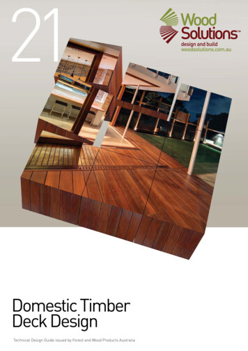
less than or equal to the allowable stresses for the material. A designmethod called load and resistance factor design (LRFD) is used for timberdesign in other countries, but not in the United States. Progress is beingmade toward development of such a method in the United States; how ever, adoption is several years away.As discussed in Chapter 3, wood strength and stiffness vary with species,growth characteristics, loading, and conditions of use. As a result, one setof allowable design values for all species and design situations wouldresult in very uneconomical design in most cases. Conversely, tabulatedvalues for all potential conditions would result in so many tables that theywould be unusable. Rather than using either of these approaches, timberdesign is based on published tabulated values that are intended for one setof standard conditions. When these conditions differ from those of thedesign application, the tabulated values are adjusted by modificationfactors to arrive at the allowable values used for each design. This ap proach produces more realistic design values for a specific situation. Ingeneral terms, the basic timber design sequence is as follows:SYMBOLS ANDABBREVIATIONS1.Compute load effects and select an initial member size andspecies.2.Compute the applied stress from applied loads.3.Obtain the tabulated stress published for the specific material.4.Determine appropriate modification factors and other adjustmentsrequired for actual use conditions.5.Adjust the tabulated stress to arrive at the allowable stress usedfor design.6.Compare applied stress to allowable stress. The design issatisfactory when applied stress is less than or equal to allowablestress.Timber design uses standard symbols to denote the types of stresses forstrength properties. These symbols consist of a stress symbol to designatethe type of stress (applied, tabulated, or allowable), followed by a lowercase subscript to denote the specific strength property (bending, shear,tension, and so forth). The symbols used for this purpose are shown inTable 5-1. For example, applied, tabulated, and allowable bending stressesare designated fb, Fb, and Fb', respectively. The same type of designationwithout the strength property subscript applies to modulus of elasticity,where E denotes the tabulated value and E' denotes the allowable value.For glulam, an additional subscript of x or y may be included to designate5-3
Table 5-1.- Stress symbols for timber components.values about the x-x or y-y axis of the member (the x-x axis for glulam isalways parallel to the wide face of the laminations). For example, Fbx isthe tabulated bending stress about the x-x axis. In the absence of such asubscript, it is assumed that stresses act about the x-x axis.TABULATED DESIGNVALUESTabulated design values for sawn lumber and glulam are based on testingand grading processes discussed in Chapter 3. These values represent themaximum permissible values for specific conditions of use and normallyrequire adjustments for actual design conditions. In this sense, tabulatedvalues should be viewed only as the basis or starting point for determiningthe allowable values to be used for design. An abbreviated summary oftabulated values for sawn lumber and glulam is published in AASHTO;however, these values do not include all species and grades and may notbe current. For this reason, AASHTO requires that tabulated values com ply with those specified in the most current edition of the NDS or AITCspecifications (AASHTO 13.1.1 and 13.2.2). The source of tabulatedvalues for sawn lumber is Design Values for Wood Construction, which isan integral part of the NDS, but is published as a separate volume. Tabu lated values for glulam are given in AITC 117-Design. These NDS andAITC specifications represent the most comprehensive and current sourceof design information and include tabulated values for the followingproperties:5-4
End grain in bearing (Fg)Modulus of elasticity (E)Tabulated Values for Sawn LumberTabulated values for visually graded and machine stress rated (MSR) sawnlumber are published in the NDS based on the grading rules established byseven grading agencies. Separate tables are included for visually gradedsawn lumber, MSR lumber, and end grain in bearing. The values are validfor sawn lumber used in dry applications under normal loading conditions(both of these conditions are discussed later for modification factors). Inaddition, each table contains an extensive set of footnotes for adjustingvalues to specific use conditions.Visually Graded Sawn LumberDesign values for visually graded sawn lumber are specified in Table 4Aof the NDS. A portion of this table is shown in Table 5-2. The table givestabulated values for Fb, Ft, Fv, Fc,and E based on the species, sizeclassification, and commercial grade of the lumber. When using the table,the following considerations will help interpret tabulated values:1.Wood species may be specified as an individual species or aspecies combination. When species combinations are used, theindividual species of the combination are listed in the Table 4Atable of contents.2.The grading rules agencies for each species are noted in the farright column of the tables. When grading rules for the samespecies differ among agencies, tabulated values are givenseparately for each grading agency.3.Tabulated values for each species are based on the grade and sizeclassification. Although commercial grade designations may bethe same, tabulated values can vary among size classifications.For example, the tabulated values for grade No. 1 in the Beamsand Stringers (B&S) size classification are not necessarily thesame as those for No. 1 in the Posts and Timbers (P&T) sizeclassification.4.For all dimension lumber that is 2 to 4 inches thick, grading rulesand commercial-grade nomenclature are standardized. When sawnlumber is thicker than 4 inches, grades are not standardized, andtabulated values for the same species, size, and grade of membermay vary among grading agencies. In situations where conflictingtabulated values are given for different agencies, the designermust either specify the grading rules agency or use the lowertabulated values.5.The availability of sawn lumber in the species, grade, and sizeclassifications in Table 4A of the NDS may be geographicallylimited. The designer should verify availability before specifyinga particular species, size, or grade.5-5
5-6
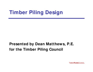
MSR LumberFor MSR lumber, tabulated values are derived by nondestructive stiffnesstesting of individual pieces that are 2 inches thick or less. Values arespecified in Table 4B of the NDS for Fb, Ft, Fc, and E based on the gradedesignation and size classification of lumber (Table 5-3). Tabulatedstresses for Fv andare as specified in NDS Table 4A for No. 2 visuallygraded sawn lumber of the appropriate species.End Grain in BearingThe NDS contains a separate table of tabulated stress for end grain inbearing, Fg. These values are specified in Table 2B of the main NDSvolume and pertain only to end-grain bearing parallel to grain on a rigidsurface. The stresses are given for each species based on member size anduse conditions and apply to both visually graded and MSR lumber.Table 5-3. -Typical tabulated values for MSR sawn lumber.5-7
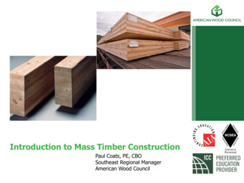
Tabulated Values for Glued-Laminated Timber (Glulam)Tabulated values for glulam are specified in AITC 117-Design. Separatetables are included for bending combinations, axial combinations, and endgrain in bearing. Values are given for western species and Southern Pinemade with either visually graded or E-rated lumber based on dry-useconditions (moisture content of 16 percent or less) and normal duration ofload. Tabulated values for a specific combination symbol of glulam arestandardized and are not subject to variations in grading rules or fabricationprocesses.Bending CombinationsFor bending combinations, tabulated values are given in Table 1 of AITC117-Design. The combination symbols in this table are for membersconsisting of four or more laminations, stressed primarily in bending withloads applied perpendicular to the wide faces of the laminations (x-x axis).The table also includes tabulated values for axial loading and bending withloads applied parallel to the wide faces of the laminations (y-y axis);however, the axial combinations are usually better suited for these loadingconditions. A limited number of combination symbols, taken from Table 1from AITC 117-Design, are shown in Table 5-4. The first two columns ofthe table give the combination symbol and species of the member. Theremainder of the table is divided into three parts based on the type anddirection of applied stress. Columns 3 to 8 contain stresses for membersloaded in bending about the x-x axis (the most common case). For thiscondition, stresses for Fb andare specified separately for the tensionand compression zones of the member. These stresses may be the same forboth zones (balanced combination) or may differ significantly. Columns 9to 13 are for members loaded in bending about the y-y axis where stressesin the tension and compression zones are equal. Columns 14 to 16 are formembers loaded axially or with a combination of axial and bending loads.The intended use and limitations for groups of combinations are also notedin the table.Axial CombinationsTabulated values for axial combinations are specified in Table 2 of AITC117-Design. The combinations in this table are intended primarily formembers loaded axially or in bending with loads applied parallel to thewide faces of the laminations (y-y axis). The table also includes tabulatedvalues for loading perpendicular to the wide faces of the laminations (x-xaxis), but bending combinations are usually better suited for this condition.A limited number of combination symbols, taken from Table 2 from AITC117-Design, are shown in Table 5-5. The table is organized in three sec tions based on the type and direction of applied stresses, as in Table 5-4.Tabulated values depend on the number of laminations and are given formembers consisting of 2, 3, and 4 or more laminations. For all axial combi nations, strength properties are balanced about the neutral axis, and tabu are equal in the tension and compressionlated stresses for Fb andzones.5-8
Table 5-4.- Typical tabulated values for glulam bending combinations.5-9
End Grain in BearingTabulated stress for end grain in bearing parallel to grain (Fg) is given inAnnex A of AITC 117-Design. Annex A consists of Tables A-1 and A-2,which specify Fg for bending combinations and axial combinations, respec tively. In both tables, Fg is specified by a combination symbol wheremember bearing is on the full cross section and where bearing is on apartial cross section.ADJUSTMENTS TOTABULATED DESIGNVALUESTabulated values for sawn lumber and for glulam are based on the standardconditions noted in the applicable design tables. When actual use condi tions vary from these standard conditions, tabulated values must be ad justed to compensate for (1) differences between the assumptions used toestablish tabulated values and actual use conditions, (2) variations in woodbehavior related to the type of stress or member orientation, and (3) differ ences between the physical or mechanical behavior of wood and that of anideal material assumed in most equations of engineering mechanics.Requirements for adjusting tabulated values are given in the text of thedesign specifications (AASHTO, NDS, and AITC 117-Design) and asfootnotes to tabulated values. The type and magnitude of the adjustments,as well as the manner in which they are applied, vary with the type ofmaterial, strength property, and design application. Most adjustments areapplied as modification factors that are multiplied by the tabulated values.These modification factors are designated by the letter C, followed by asubscript to denote the type of modification. They include the following:CM moisture content factorCL lateral stability of beams factorCD duration of load factorCP lateral stability of columns factorCt temperature factorCR fire-retardant treatment factorCf form factorCC curvature factorCF size factorCI interaction stress factorModification factors are applied to tabulated values only, not to appliedstresses or loads. In most cases they are cumulative; however, in somecases the more restrictive value of two factors is used. A summary of theapplicability of modification factors to various wood properties is given inTable 5-6. The factors CC and CI apply to curved and taper-cut glulambeams, respectively, and are not discussed in this chapter. Refer to theAITC Timber Construction Manual for additional information on these6factors.Moisture Content Factor CM)The strength and stiffness of wood decrease as moisture content increases.To compensate for this effect, tabulated values are adjusted by CM. Thisfactor, which is also referred to as a wet-use factor or condition-of-use5-11
Table 5-6.- Applicability of modification factors for strength properties and modulus of elasticity.factor, is applicable to all tabulated values for strength and modulus ofelasticity. It adjusts values for changes in strength and stiffness and com pensates for variations in cross section caused by shrinkage.Application of CM differs for sawn lumber and glulam. For sawn lumber,tabulated values are based on the moisture content specified for eachspecies in the NDS tables. With the exception of Southern Pine and Vir ginia Pine-Pond Pine, adjustment by CM is applied when the moisturecontent of the member in service is expected to exceed 19 percent. ForSouthern Pine and Virginia Pine-Pond Pine, the CM adjustment is notrequired because tabulated values are given in the design tables for threein-service moisture contents. These tabulated values already include theCM adjustment, and no further adjustment for moisture is required. Valuesof CM for all other lumber species are given in the footnotes to the designtables and depend on the member size and specific strength property(Table 5-7).For glulam, all tabulated values in AITC 117-Design are based on amoisture content in service of 16 percent or less. When the moisturecontent in service is expected to be 16 percent or higher, tabulated valuesmust be multiplied by the wet-use factors given in the design tables.Factor CM for glulam depends on the strength property only and is inde pendent of species, combination symbol, and member size. Values of CMfor glulam are given in Table 5-7.In most applications, bridge members are exposed to the weather andshould be adjusted by CM for wet-use conditions. In cases where beams areprotected by a waterproof deck, design for dry conditions may be appro priate, as discussed in Chapter 7.5-12
Table 5-7. - Values of the moisture content factor CM for sawn lumber and glulam.Duration of load Factor (CD)Wood is capable of withstanding much greater loads for short durationsthan for long periods. This is particularly significant in bridge designwhere short-term increased loads from vehicle overloads, wind, earth quake, or railing impact must be considered. The tabulated values forsawn lumber and glulam are based on an assumed normal duration ofload. In this case, a normal duration of load is based on the expectationthat members will be stressed to the maximum stress level (either continu ously or cumulatively) for a period of approximately 10 years, stressed to90 percent of the maximum design level continuously for the remainder ofthe life of the structure, or both. This maximum stress is assumed to occurduring the life of the member as a result of either continuous loading or aseries of shorter duration loads that total 10 years. When the maximumdesign loads act for durations that are shorter or longer than these assumeddurations, tabulated stresses are adjusted by CD, (Table 5-8). Factor CDapplies to tabulated strength properties but does not apply to compressionperpendicular to grainor modulus of elasticity (E). In most bridge5-13
Table 5-8.Modification factors for duration of load.Load duration2 months (as for snow and ice)7 days (as for snow and ice)Wind or earthquake5 minutes (rail loads only)aDuration of loadfactor CD1.151.251.33a1.65The duration of load factor for impact does not apply to members pressure-impregnated withpreservative salts to the heavy retentions required for marine exposure, or sawn lumber treatedwith fire-retardant chemicals.From AASHTO Section 13.2.5.1:1 8 1983. Used by permission.applications, the permanent load of the structure is small in relation tovehicle loads, and a decrease in tabulated stresses for permanent loading isnot necessaryThe stresses produced in bridge members are commonly the result of acombination of loads rather than a single load (Chapter 6). For a combina tion of loads of different durations, CD for the entire group is the singlevalue associated with the shortest load duration. When applying CD, thedesigner must recognize that for a given combination of loads, the mostrestrictive allowable stress may result from a partial combination involv ing loads of longer duration. The individual loads in a load combinationmust be evaluated in various combinations, with the value of CD depend ing on the load of shortest duration for that combination. This is accom plished by progressively eliminating the load of shortest duration from thegroup and applying CD for the load of next-shortest duration. In otherwords, the resulting size or capacity of a member required for a loadcombination must not be less than that required for a partial combinationof the longer-duration loads. Application of CD is discussed in more detailin Appendix B of the NDS and in Chapter 6. Duration of load is generallynot applicable in bridge design, except for the design of railing systems.Temperature Factor (Ct)The strength and stiffness of wood increases as it cools and decreases as itwarms. These changes in strength because of temperature occur immedi ately and depend on the magnitude of the temperature change and themoisture content of the wood. For temperatures up to approximately150 OF, the immediate effects of strength loss are reversible, and the mem ber will essentially recover its initial strength levels as the temperature isOlowered. Prolonged exposure to temperatures higher than 150 F maycause a permanent and irreversible loss in member strength.Tabulated design values for sawn lumber and glulam assume that mem bers will be used in normal temperature applications and may occasionally5-14
be heated to temperatures up to 150 OF. This applies to most bridge designsituations. In cases where a member may be periodically exposed toelevated temperatures, humidity is generally low, and the increase inmember strength that results from reduced moisture tends to offset thereduction in strength that results from temporary temperature increases.The design specifications do not require a mandatory adjustment to tabu lated values for temperature effects, and as a general rule, none are war ranted. In cases where members will be exposed to prolonged tempera Otures in excess of 150 F, or will be used at very low temperatures for theentire design life, the modification factor, Ct, given in Table 5-9, may beapplied at the discretion of the designer.Table 5-9. - Temperature factor Ct given as a percentageincrease orOdecrease in design values for each 1 F decrease or increasein temperature.Fire-Retardant Treatment Factor (CR)Fire-retardant treatments are seldom used on bridge members and areunnecessary in most applications. For those situations where fire-retardantchemicals are considered necessary, tabulated values must be adjusted bythe fire-retardant treatment factor CR. The value for this factor depends onspecific strength properties and is different for sawn lumber and glulam.CR is given for sawn lumber in Table 2A of the NDS (Table 5-10). Thebasis for these values and treatment qualifications are outlined in Appen dix Q of the NDS. CR for glulam depends on the species and treatmentcombinations involved. The effects on strength properties must be deter mined for each treatment. However, indications are that 10 to 25 percent4,6reductions in bending strength are applicable. The treatment manufac turer should be contacted for more specific CR values for glulam based onthe specific material and design application.5-15
Table 5-10.- Fire-retardant treatment factor for structural lumber.PropertyCRExtreme fiber in bendingTension parallel to grainHorizontal shearCompression perpendicular to grainCompression parallel to grainModulus of elasticityFastener design loads0.850.800.900.900.900.900.90From the NDS; 26 8 1986. Used by permission.Size Factor (CF)Tabulated bending stresses are based on a square or rectangular member12 inches deep in the direction of applied loads. For member depthsgreater than 12 inches, Fb must be adjusted by CF, as computed by(5-1)where d is the member depth in inches.For sawn lumber, CF does not apply to MSR lumber or to visually gradedlumber 2 to 4 inches thick used edgewise. For glulam, the CF value com puted by the above equation is based on a uniformly distributed load on asimply supported beam with a span to depth ratio L/d 21. In most bridgeapplications, these assumptions result in reasonable accuracy as variationsin loading and L/d result in relatively small deviations in the size factor. Incases where greater accuracy is warranted, CF may be adjusted for otherL/d ratios or loading conditions by the percentages in Table 5-11.The effect of the size factor for both sawn lumber and glulam is to reducethe tabulated bending stress for members more than 12 inches deep. Formembers less than 12 inches deep, footnotes to design tables allow anincrease in bending stress for sawn lumber members 2 to 4 inches thick24used flatwise, and glulam members loaded parallel to the wide faces ofthe laminations.4 CF is generally cumulative with other modificationfactors, but is normally not cumulative with the lateral stability of beamsfactor, CL (see Sections 5.4 and 5.7).Equation 5-1, used for computing size factor, is being reevaluated forglulam, and alternate forms of the equation are being considered byseveral industry-related technical committees. Thus, the designer shouldbe aware of the potential for future revisions and refer to the latest editionsof the NDS and AITC 117-Design for current requirements.5-16
Lateral Stability of Beams Factor (CL)The lateral stability of beams factor, CL, is applied to some bending mem bers where the compressive stress in bending must be limited to preventlateral buckling. Additional details on the use of CL are discussed inSection 5.4.Form Factor (Cf)Tabulated bending stresses are based on members with a square or rectan gular cross section loaded normal to one or more faces. For other membershapes, specifically round or diamond sections, stresses must be modifiedby the form factor, Cf. Cf does not apply to rectangular or square membersand is not commonly used in bridge applications. Refer to the NDS foradditional information on the use of Cf.Lateral Stability of Columns Factor (CP)The lateral stability of columns factor, CP, is applied to some compressionmembers where the compressive stress must be limited to prevent lateralbuckling. Additional details on the use of CP are discussed in Section 5.6.5.4 BEAM DESIGNA beam is a structural component with loads applied transversely to thelongitudinal axis. In bridge design, beams are the most frequently usedstructural components. The three most common bridge beams are girders,stringers, and floorbeams. Girders are large beams (normally glulam) thatprovide primary superstructure support, most often in beam-type super structures. Stringers are longitudinal beams that support the bridge deck.5-17
They are generally smaller than girders, but there is no clear size defini tion for either. Floorbeams are transverse beams that directly support thebridge deck or support longitudinal stringers that support the deck. Inaddition to girders, stringers, and floorbeams, other bridge components aredesigned as beams, including components of the deck and railing systems.Beam design involves the analysis of member strength, stability, andstiffness for four basic criteria: (1) bending (including lateral stability),(2) deflection, (3) horizontal shear, and (4) bearing. Of these four criteria,bending, deflection, and shear can directly control member size, whilebearing will influence the design of supports. Initial beam design is nor mally based on bending, then checked for deflection and shear. After anappropriate beam size is determined, bearing stresses are checked atsupports to ensure sufficient bearing area.Beam design requirements discussed in this section are limited to straightor slightly curved (cambered) solid rectangular beams of constant crosssectional area. Refer to the NDS for design requirements for other bea
timber design requirements, procedures, and recommendations addressed in this manual. The majority of the timber design requirements in AASHTO are based on the National Design Specification for Wood Construction (NDS). 26 The NDS is the most