Transcription
1Steel Design GuideBase Plate andAnchor Rod DesignSecond Edition
1Steel Design GuideBase Plate andAnchor Rod DesignSecond EditionJAMES M. FISHER, Ph.D., P.E.Computerized Structural Design, S.C.Milwaukee, WisconsinandLAWRENCE A. KLOIBER, P.E.LeJuene Steel CompanyMinneapolis, MinnesotaAMERICAN INSTITUTE O F S T E E L C O N S T RU C T I O N , I N C.
Copyright 2006byAmerican Institute of Steel Construction, Inc.All rights reserved. This book or any part thereofmust not be reproduced in any form without thewritten permission of the publisher.The information presented in this publication has been prepared in accordance with recognizedengineering principles and is for general information only. While it is believed to be accurate,this information should not be used or relied upon for any specific application without competent professional examination and verification of its accuracy, suitability, and applicability by alicensed professional engineer, designer, or architect. The publication of the material containedherein is not intended as a representation or warranty on the part of the American Instituteof Steel Construction or of any other person named herein, that this information is suitable forany general or particular use or of freedom from infringement of any patent or patents. Anyonemaking use of this information assumes all liability arising from such use.Caution must be exercised when relying upon other specifications and codes developed by otherbodies and incorporated by reference herein since such material may be modified or amendedfrom time to time subsequent to the printing of this edition. The Institute bears no responsibility for such material other than to refer to it and incorporate it by reference at the time of theinitial publication of this edition.Printed in the United States of AmericaFirst Printing: May 2006
AcknowledgementsThe authors would like to thank Robert J. Dexter fromthe University of Minnesota, and Daeyong Lee from theSteel Structure Research Laboratory, Research Institute ofIndustrial Science & Technology (RIST), Kyeonggi-Do,South Korea, for their writing of Appendix A and the firstdraft of this Guide. The authors also recognize the contributions of the authors of the first edition of this guide, JohnDeWolf from the University of Connecticut and DavidRicker (retired) from Berlin Steel Construction Company,and thank Christopher Hewitt and Kurt Gustafson of AISCfor their careful reading, suggestions, and their writing ofAppendix B. Special appreciation is also extended to CarolT. Williams of Computerized Structural Design for typingthe manuscript.AISC would also like to thank the following individualswho assisted in reviewing the drafts of this Design Guide fortheir insightful comments and suggestions.Victoria ArbitrioReidar BjorhovdeCrystal BlantonCharles J. CarterBrad DavisRobert O. DisqueJames DoyleRichard M. DrakeSamuel S. EskildsenDaniel M. FalconerMarshall T. FerrellRoger D. HamiltonJohn HarrisAllen J. HarroldvDonald JohnsonGeoffrey L. KulakBill R. Lindley IIDavid McKenzieRichard OrrDavis G. Parsons IIWilliam T. SeguiDavid F. SharpVictor ShneurBozidar StojadinovicRaymond TideGary C. VioletteFloyd J. Vissat
vi
Table of Contents1.0 INTRODUCTION .12.0 MATERIAL, FABRICATION,INSTALLATION, AND REPAIRS . 22.13.4Material Specifications . 22.22.32.42.52.62.72.82.9Base Plate Material Selection. 2Base Plate Fabrication and Finishing . 3Base Plate Welding . 4Anchor Rod Material . 5Anchor Rod Holes and Washers. 6Anchor Rod Sizing and Layout . 7Anchor Rod Placement and Tolerances . 7Column Erection Procedures . 82.9.1 Setting Nut and Washer Method. 82.9.2 Setting Plate Method . 92.9.3 Shim Stack Method . 92.9.4 Setting Large Base Plates . 92.10 Grouting Requirements . 92.11 Anchor Rod Repairs . 102.11.1 Anchor Rods in the Wrong Position . 102.11.2 Anchor Rods Bent or Not Vertical . 102.11.3 Anchor Rod Projection Too Longor Too Short . 102.11.4 Anchor Rod Pattern Rotated 90 . 122.12 Details for Seismic Design D . 123.54.0 DESIGN EXAMPLES .314.13.23.3Example: Base Plate for Concentric AxialCompressive Load(No concrete confinement) . 314.2Example: Base Plate for Concentrix AxialCompressive Load(Using concrete confinement) . 324.3 Example: Available Tensile Strength of aw-in. Anchor Rod . 344.4 Example: Concerete Embedment Strength . 344.5 Example: Column Anchorage forTensile Loads . 344.6 Example: Small Moment Base Plate Design . 374.7 Example: Large Moment Base Plate Design . 384.8 Example: Shear Transfer Using Bearing . 404.9 Example: Shear Lug Design. 404.10 Example: Edge Disttance for Shear . 424.11 Example: Anchor Rod Resisting CombinedTension and Shear . 423.0 DESIGN OF COLUMN BASEPLATE CONNECTIONS .133.13.3.3 Base Plate Flexural Yieldingat Tension Interface. 253.3.4 General Design Procedure . 25Design of Column Base Plates withLarge Moments . 253.4.1 Concrete Bearing andAnchor Rod Forces . 253.4.2 Base Plate Yielding Limitat Bearing Interface . 263.4.3 Base Plate Yielding Limitat Tension Interface. 273.4.4 General Design Procedure . 27Design for Shear . 273.5.1 Friction . 273.5.2 Bearing . 273.5.3 Shear in Anchor Rods . 293.5.4 Interaction of Tension andShear in the Concrete . 303.5.5 Hairpins and Tie Rods . 30Concentric Compressive Axial Loads . 143.1.1 Concrete Bearing Limit . 143.1.2 Base Plate Yielding Limit(W-Shapes) . 153.1.3 Base Plate Yielding Limit(HSS and Pipe) . 163.1.4 General Design Procedure . 16Tensile Axial Loads . 183.2.1 Anchore Rod Tension . 193.2.2 Concrete Anchorage forTensile Forces . 19Design of Column Base Plates withSmall Moments. 233.3.1 Concrete Bearing Stress . 243.3.2 Base Plate Flexural YieldingLimit at Bearing Interface . 24REFERENCES.45APPENDIX A . 47APPENDIX B . 55vii
viii
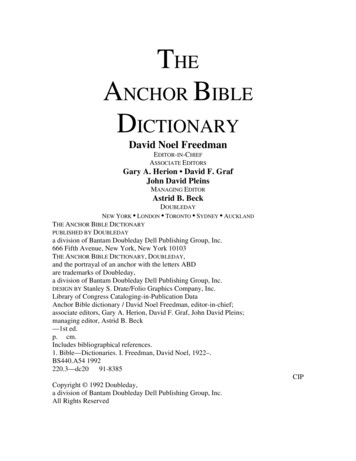
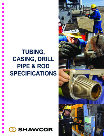
1.0 INTRODUCTIONColumn base plate connections are the critical interfacebetween the steel structure and the foundation. These connections are used in buildings to support gravity loads andfunction as part of lateral-load-resisting systems. In addition,they are used for mounting of equipment and in outdoor support structures, where they may be affected by vibration andfatigue due to wind loads.Base plates and anchor rods are often the last structuralsteel items to be designed but are the first items requiredon the jobsite. The schedule demands along with the problems that can occur at the interface of structural steel andreinforced concrete make it essential that the design detailstake into account not only structural requirements, but alsoinclude consideration of constructability issues, especiallyanchor rod setting procedures and tolerances. The importance of the accurate placement of anchor rods cannot beover-emphasized. This is the one of the key components tosafely erecting and accurately plumbing the building.The material in this Guide is intended to provide guidelinesfor engineers and fabricators to design, detail, and specifycolumn-base-plate and anchor rod connections in a mannerthat avoids common fabrication and erection problems. ThisGuide is based on the 2005 AISC Specification for Structural Steel Buildings (AISC, 2005), and includes guidance fordesigns made in accordance with load and resistance factordesign (LRFD) or allowable stress design (ASD).This Guide follows the format of the 2005 AISC Specification, developing strength parameters for foundation system design in generic terms that facilitate either load andresistance factor design (LRFD) or allowable strength design (ASD). Column bases and portions of the anchoragedesign generally can be designed in a direct approach basedon either LRFD or ASD load combinations. The one areaof anchorage design that is not easily designed by ASD isthe embedment of anchor rods into concrete. This is due tothe common use of ACI 318 Appendix D, which is exclusively based on the strength approach (LRFD) for the designof such embedment. Other steel elements of the foundationsystem, including the column base plate and the sizing ofanchor diameters are equally proficient to evaluation usingLRFD or ASD load methods. In cases such as anchors subjected to neither tension nor shear, the anchorage development requirement may be a relatively insignificant factor.The generic approach in development of foundation design parameters taken in this Guide permits the user a choiceto develop the loads based on either the LRFD or ASD approach. The derivations of foundation design parameters, aspresented herein, are then either multiplied by the resistancefactor, φ, or divided by a safety factor, Ω, based on the appropriate load system utilized in the analysis; consistentwith the approach used in the 2005 Specification. Many ofthe equations shown herein are independent of the load approach and thus are applicable to either design methodology.These are shown in singular format. Other derived equationsare based on the particular load approach and are presentedin a side-by-side format of comparable equations for LRFDor ASD application.The typical components of a column base are shown inFigure 1.1.Material selection and design details of base plates cansignificantly affect the cost of fabrication and erection ofsteel structures, as well as the performance under load.Relevant aspects of each of these subjects are discussedbriefly in the next section. Not only is it important to designthe column-base-plate connection for strength requirements,it is also important to recognize that these connectionsaffect the behavior of the structure. Assumptions aremade in structural analysis about the boundary conditionsrepresented by the connections. Models comprising beam ortruss elements typically idealize the column base connectionas either a pinned or fixed boundary condition. Impropercharacterization can lead to error in the computed drifts,leading to unrecognized second-order moments if thestiffness is overestimated, or excessive first-floor columnsizes if the stiffness is underestimated. If more accurateanalyses are desired, it may be necessary to input the stiffnessof the column-base-plate connection in the elastic and plasticranges, and for seismic loading, possibly even the cyclicforce-deformation relations. The forces and deformationsfrom the structural analyses used to design the column-baseplate connection are dependent on the choice of the columnbase-plate connection details.Figure 1.1. Column base connection components.DESIGN GUIDE 1, 2ND EDITION / BASE PLATE AND ANCHOR ROD DESIGN / 1
Table 2.1. Base Plate MaterialsThickness (tp)Plate Availabilitytp 4 in.ASTM A36 [a]ASTM A572 Gr 42 or 50ASTM A588 Gr 42 or 504 in. tp 6 in.ASTM A36 [a]ASTM A572 Gr 42ASTM A588 Gr 42tp 6 in.ASTM A36[a]Preferred material specificationThe vast majority of building columns are designed foraxial compression only with little or no uplift. For such columns, the simple column-base-plate connection detail shownin Figure 1.1 is sufficient. The design of column-base-plateconnections for axial compression only is presented in Section 3. The design is simple and need not be encumberedwith many of the more complex issues discussed in Appendix A, which pertains to special structures. Anchor rods forgravity columns are often not required for the permanentstructure and need only be sized to provide for column stability during erection.Column base plate connections are also capable of transmitting uplift forces and can transmit shear through the anchor rods if required. If the base plate remains in compression, shear can be transmitted through friction against thegrout pad or concrete; thus, the anchor rods are not requiredto be designed for shear. Large shear forces can be resistedby bearing against concrete, either by embedding the column base or by adding a shear lug under the base plate.Column base plate moment connections can be used toresist wind and seismic loads on the building frame. Momentat the column base can be resisted by development of a forcecouple between bearing on the concrete and tension in someor all of the anchor rods.This guide will enable the designer to design and specifyeconomical column base plate details that perform adequately for the specified demand. T
B.4.1 Design Procedure for a Small Moment Base 1. Choose trial base plate sizes (B and N) based on geom- etry of column and four-anchor requirements. N d (2 3 in.) B bf (2 3 in.) 2. Determine plate cantilever dimension, m or n, in direc- tion of applied moment. m (N 0.95d) / 2 n (B -