Transcription
NOTE: JULY 2018The Timber Bridge Manual is a reference documentonly. Some of the contents are out-of-date.It is recommended to seek advice from RMS Bridgeand Structural Engineering (Rehabilitation Design) priorto use.TIMBER BRIDGE MANUALEdition 1 Revision 0 – June 2008SECTION SEVENTIMBER CONCRETE COMPOSITE BRIDGES
TIMBER BRIDGE MANUALEDITION 1 R 0TABLE OF CONTENTSSECTION SEVEN7.TIMBER-CONCRETE COMPOSITE BRIDGES17. 1 GENERAL7. 1.1Scope7. 1.2Objectives7. 1.3Definitions7. 1.4Limits of Application111117. 2STRUCTURE TYPES AND COMPONENTS7. 2.1Design Features7. 2.2Timber Girders7. 2.3Concrete Deck and Diaphragms7. 2.4Timber-Concrete Interface Connection223447. 3INSPECTION PROCEDURES7. 3.1Objectives and General Requirements7. 3.2Inspection Records7. 3.3Annual Visual Inspection7. 3.4Observation under Transient Loading7. 3.5Concrete Cracking and Crushing7. 3.6Bearing Restraint and Joint Gap7. 3.7Timber Girders - Structural Failure and Damage7. 3.8Timber Girders - Deterioration7. 3.9Additional Items for Annual Visual Inspection7. 3.10 Detailed Inspection7. 3.11 Timber Boring7. 3.12 Monitoring and Testing5555667889910107. 4PREVENTATIVE AND ROUTINE MAINTENANCE7. 4.1Objectives and General Requirements7. 4.2Preventative Maintenance7. 4.3Annual Maintenance7. 4.4Three Year Maintenance11111111117. 5REHABILITATION AND REPAIRS7. 5.1Cracking in Concrete Slab7. 5.2Cracking in Haunches7. 5.3Failed Shear Connectors7. 5.4Timber Deterioration12121212137. 613ENGINEERING EVALUATION7. 7DETAILING AND DURABILITY7. 7.1Recommended Details(i)1314
7. 7.214Construction and Durability7. 8CONSTRUCTION SPECIFICATIONS7. 8.1Timber Girder Fabrication7. 8.1.1 General7. 8.1.2 Timber Girder Sizing7. 8.2Timber-Concrete Composite Connection7. 8.2.1 Positioning of Coach Screws7. 8.2.2 Installation of Coach Screws7. 8.2.3 Installation of Shear Plate Connectors7. 8.2.4 Installation of End Channel Shear Connector7. 8.3Formwork and Casting Bed7. 8.3.1 General7. 8.3.2 Casting Bed7. 8.3.3 Formwork Geometry7. 8.3.3.1 Concrete Deck Thickness7. 8.3.3.2 Precamber7. 8.3.3.3 End Concrete Diaphragms7. 8.3.4 Positioning and Support of Timber Girders7. 8.4Concrete and Reinforcement7. 8.4.1 General7. 8.4.2 Reinforcement Placement7. 8.4.3 Concrete Placement7. 8.4.4 Concrete Finish7. 8.4.5 Curing7. 8.5Handling and Transportation of Modules7. 8.5.1 General7. 8.5.2 Lifting of Modules7. 8.5.3 Transportation of 222232323237. 9Material Supply7. 9.1Timber Girders7. 9.2Concrete7. 9.3Reinforcement7. 9.4Coach Screws7. 9.5Steel Shear Connectors7. 9.6Other Steel Hardware7. 9.7Protective Treatment2424242424242525(ii)
LIST OF FIGURESFigure 7.2-1Figure 7.2.1-1Figure 7.2.2-1Figure 7. 2.2-2Figure 7.2.4-1Figure 7. 2.4-2Figure 7.3.5-1Figure 7.3.5-2Figure 7.3.6-1Figure 7.3.7-1Figure 7.3.8-1Figure 7.3.12-1Figure 7.5.3-1Figure 7.7.1-1Figure 7. 8.1.2-1Figure 7.8.1.2-2Figure 7.8.2.1-1Figure 7.8.2.3-1Figure 7. 8.3.3.3-1Figure 7.8.3.3.3-2Figure 7.8.4.3-1Figure 7.8.4.4-1Deck Modules at RTA Fabrication Yard (Grafton)Elevation of Deck ModuleSection through Timber GirderTypical Sizing at End of Timber GirderShear Plates and Coach Screw ConnectorsTypical Shear Plates and Coach ScrewsPotential Cracking in ModulesPotential Crushing of ConcreteBearing Restraint and Joint BlockagePotential Timber Failure AreasPotential Timber Deterioration AreasInstrumentation to Measure Slip and SeparationTemporary Repairs to Shear ConnectorsTypical Detailing - Macleay River BridgeTypical Girder SectionTypical Girder End SectionPositioning of Coach ScrewsInstallation of Shear PlatesTaper of End Face of Concrete DiaphragmsTaper of Sides of Concrete DiaphragmsPlacement of Concrete in End DiaphragmsDrip Edge and Concrete Level(iii)233445778891013141516171820202122
TIMBER BRIDGE MANUAL7.EDITION 1 R 0TIMBER-CONCRETE COMPOSITE BRIDGES7. 1 GENERAL7. 1.1 ScopeSection 7 covers the design, construction and maintenance of timber-concretecomposite (TCC) bridge systems and specified components as outlined inSubsection 7.2. While it may be used for all types of timber-concrete compositesystems, it is directed towards the more recently developed composite modulardecks. Its use applies only to approved composite designs which use Australianhardwood species.This section is to be read in conjunction with Section 1- General and othersections as may be specified. Section 1 provides the basic requirements andprocedures for timber bridges and their components. This section providesspecific additional requirements relating to timber- concrete composite bridgesystems.7. 1.2 ObjectivesThe objectives of this sections are to outline the requirements of, and to provideguidance in relation to, the design, construction and maintenance of timberconcrete composite bridge systems with specific emphasis on: inspection procedurespreventative and routine maintenancerehabilitation and repairsengineering design and evaluationspecificationsmaterial supply7. 1.3 DefinitionsSection 1 contains an extensive list of definitions pertaining to commonterminologies, phrases and components related to timber bridges. This currentsubsection provides additional definitions related specifically to timber-concretecomposite bridges.Cast-In:A term referring to items installed prior to a concrete pour and formingpart of the finished moduleSection SevenPage 1 of 25
TIMBER BRIDGE MANUALEDITION 1 R 0Concrete Deck:The top concrete slab of the moduleDiaphragms:The Concrete end support sections of the moduleTCC Deck:A term referring to the specific timber-concrete bridge module developedby the RTA at Grafton.Drip Edge:A V groove on the underside of the concrete adjacent to the edgesprovided to prevent water running under the deck to the timber girdersLong Term Deflection:The accumulated vertical deflection of the module over time caused byrepeated loading and drying of the timberModule:A completed timber-concrete bridge deck unitPrecamber:A term referring to the intentional introduction of upwards verticalcurvature to offset the effects of the mass of the module and long termdeflectionShear Connectors:The steel plates and end channels embedded into the top surface of thetimber girdersPrincipal’s Representative:The nominated representative of the PrincipalTimber Girder Fabrication:The trimming, sizing and grooving of the timber girders includinginstallation of shear connectors and coach screwsTimber-Concrete Composite Connection:The combined assembly of steel plate, channel and coach screw at thetimber-concrete interface7. 1.4 Limits of ApplicationThe use of timber-concrete composite bridge systems is not a new concept andthere are varied designs that have been used around the world, particularly inNorth America. However, nearly all of the North American systems usesoftwood timbers in conjunction with composite concrete slabs.Section SevenPage 1 of 25
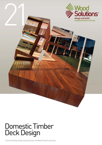
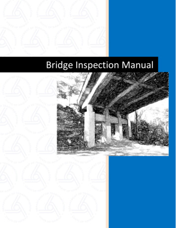
TIMBER BRIDGE MANUALEDITION 1 R 0While the following information may apply to all types of TCC systems, RTAuse relates only to approved composite designs which use Australian hardwoodspecies.7. 2 STRUCTURE TYPES AND COMPONENTSThis section deals specifically with the modular TCC deck shown inFigure 7.2-1. This design typically uses two timber girders made composite witha concrete deck to form an individual bridge deck module.Figure 7.2-1 Deck Modules at RTA Fabrication Yard (Grafton)These modules are prefabricated to sizes which can easily be transported tosite and installed by crane or mobile gantry.7. 2.1 Design FeaturesWhile specific engineering design and standard details will be outlined inSubsections 7.6 and 7.7, the following provides a brief resume of the basiccomponents and materials.Detailing of the TCC deck has been developed to counter the effects of timbershrinkage which can usually cause separation at the interface of compositesystems. This new design features support of the timber girder through itscomposite connection to the concrete deck as shown in Figure 7.2.1-1. In thisregard, the girder has no specific support or attachment at the traditional endbearing areas as shown in the figure. Therefore, as the girder dries, theshrinkage (dimensional change) in the girder occurs towards the concreteminimising the effects at the interface.Section SevenPage 2 of 25
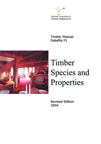
TIMBER BRIDGE MANUALFigure 7.2.1-1EDITION 1 R 0Elevation of Deck Module7. 2.2 Timber GirdersTimber girders are selected from quality grade Australian hardwood specieswith a minimum stress grade of F27 and Durability Class 1. The member sizesare based on specific design requirements, but generally will not be less than350 mm diameter at the smallest end section.They are provided with flat surfaces on the top and fitted with steel plate shearconnectors as shown in Figure 7.2.2-1 and the girders are trimmed and shapedat the ends to specific dimensions to suit their integration into the castingformwork as shown Figure 7. 2.2-2.Figure 7.2.2-1Section SevenSection through Timber GirderPage 3 of 25
TIMBER BRIDGE MANUALFigure 7. 2.2-2EDITION 1 R 0Typical Sizing at End of Timber Girder7. 2.3 Concrete Deck and DiaphragmsThe concrete deck is cast integrally with the end diaphragms which provide theend support bearing for the modules. The design detailing of the concrete andreinforcement, as specified in Subsection 7.7, is critical to the performance ofthese modules. The concrete is designed to carry all the vertical shear forces.7. 2.4 Timber-Concrete Interface ConnectionIn order to provide composite action between the concrete and timber, as wellas support to the girder, a series of shear plates and coach screws are used asshown in Figures 7.2.4-1 and 7.2.4-2. The coach screws provide the supportattachment for the girder to ensure it remains close to the concrete. The shearplates provide the horizontal shear strength between the two materials.Figure 7.2.4-1Section SevenShear Plates and Coach Screw ConnectorsPage 4 of 25
TIMBER BRIDGE MANUALFigure 7. 2.4-2EDITION 1 R 0Typical Shear Plates and Coach Screws7. 3 INSPECTION PROCEDURESSection 1 outlines the basic detailed inspection procedures for all timber bridgetypes and these procedures also apply to timber-concrete composite bridges.This subsection highlights specific additional considerations for timber-concretecomposite bridges.7. 3.1 Objectives and General RequirementsThe basic objectives and requirements outlined in Section 1 must beconsidered during the inspection of TCC bridges. Specific attention must begiven to both the concrete and timber elements, particularly the interface shearconnections for any signs of distress or deterioration.7. 3.2 Inspection RecordsDetailed inspection records as outlined in Section 1 must be maintained for allinspections.7. 3.3 Annual Visual InspectionAnnual visual inspections should be carried out on all TCC bridges and shouldbe done together with the annual maintenance as outlined in Section 1.The visual inspection shall include: all exposed components of the TCC module observation of the bridge under transient loadingSection SevenPage 5 of 25
TIMBER BRIDGE MANUALEDITION 1 R 0 identification of any obvious structural defects and damage with specificemphasis on concrete cracking and timber/concrete failure at the shearconnectors identification of any obvious deterioration specific attention to previously reported problem areas in past inspectionrecordsDue to the unique nature of the TCC bridge system, as compared to thetraditional timber bridges, some additional information is presented in thefollowing sections.7. 3.4 Observation under Transient LoadingThe bridge should be observed under transient loading as outlined in Section 1.Specific attention should be given to: overall vertical displacement of the bridgerelative movement between different modulesrelative slip of the timber and concrete componentsmovement of the shear plate connectorsseparation of the timber and concrete componentsAny suspected excessive movements should be followed up by a detailedinspection of the interface connection.7. 3.5 Concrete Cracking and CrushingAll areas of the concrete should be inspected for cracking or crushing.These modules are usually cast upside down and when they are placed in theupright position the concrete deck sustains some compression which offsetsthe potential shrinkage effects in the slab. Any cracks in the slab, particularlylongitudinal cracks, should be recorded and reported immediately.The end diaphragms should be inspected for structural cracking. Laboratorytesting has identified several potential failure mechanisms at the enddiaphragms which could cause cracking. The most prominent areas are shownin Figure 7.3.5-1. The cracks initiating at the corners of the haunch would betypically caused by flexural loading of the module. However, the crackinginitiating at the top and end surfaces would be caused by bearing restraint orlack of gap behind the end of the module as outlined in Subsection 7.3.6.Section SevenPage 6 of 25
TIMBER BRIDGE MANUALFigure 7.3.5-1EDITION 1 R 0Potential Cracking in ModulesParticular attention should also be given to the concrete at the shearconnectors. Overstressing of the concrete at the shear plates will result incrushing and spalling of the concrete in front of the plates as shown in theFigure 7.3.5-2.Figure 7.3.5-2Potential Crushing of Concrete7. 3.6 Bearing Restraint and Joint GapCracking of the concrete can occur as a result of gradual build-up of debrisbehind the ends of the modules which prevents the normal rotation of thediaphragms under heavy loads as shown in Figure 7.3.6-1. It can also becaused by no gap being provided between modules during construction. This isaccentuated for modules with very deep haunches. In addition, if no gap isprovided, temperature can also play a significant role in producing internalforces. These areas between modules must be kept clear.Section SevenPage 7 of 25
TIMBER BRIDGE MANUALFigure 7.3.6-1EDITION 1 R 0Bearing Restraint and Joint Blockage7. 3.7 Timber Girders - Structural Failure and DamageThe potential failure and damage zones for the timber girder are flexural failure at mid-span horizontal splitting of the girder (see Figure 7.3.7-1) localised shear failure in the timber at the shear plate (see Figure 7.3.7-1) withdrawal of coach screws (separation of components)Figure 7.3.7-1Potential Timber Failure Areas7. 3.8 Timber Girders - DeteriorationPotential deterioration of the timber (ie: decay or insect attack) is highest at thetimber-concrete interface, particularly at the ends of the girders(see Figure 7.3.8-1). If moisture accesses these areas, it is likely that thedeterioration would be concentrated at the connectors which penetrate theSection SevenPage 8 of 25
TIMBER BRIDGE MANUALEDITION 1 R 0timber. Typically, only a detailed boring of the girder would expose theseproblems as is outlined in Subsection 7.3.11.Figure 7.3.8-1Potential Timber Deterioration Areas7. 3.9 Additional Items for Annual Visual InspectionThe annual visual inspection should include the following additional items: visual signs of timber deteriorationconcrete cracking in slab and haunchesconcrete crushing and spalling at shear plateslocalised timber shear failure at shear platesgirder splitting at endsseparation of the timber and concrete components7. 3.10 Detailed InspectionA more detailed inspection should be carried out on timber bridges every threeyears. In the case of the composite bridge modules, this would consist of timberboring to evaluate the internal condition of the girders as outlined inSubsection 7.3.11.If structural problems have been discovered, then the detailed inspectionshould include: mapping and marking concrete cracksmonitoring crack propagationmeasuring interface slipmeasuring component separationpossible load testingSome additional details on monitoring and testing are outlined inSubsection 7.3.12.Section SevenPage 9 of 25
TIMBER BRIDGE MANUALEDITION 1 R 07. 3.11 Timber BoringThe standard methods and identification for timber test boring are outlined inSection 1 and shall be applied to TCC bridges. However, with compositemodules, there are several additional points to consider: the ends of the girders and other contact areas with the concrete are themost susceptible to deterioration the ends of the timber girders are embedded in the concrete and so it isnecessary to drill in on an angle in order to properly check their ends(see Figure 7.3.8-1) cracked slabs will allow moisture to reach the tops of the girdersThe boring lines to be adopted are shown in Figure 7.3.8-1. Vertical boresshould extend up to the vicinity of the concrete slab (within 50 mm) but notcompletely through the girder.7. 3.12 Monitoring and TestingIn cases where structural damage is observed, it is important to evaluate theextent of the damage, particularly its effect on the performance of thecomposite module. Problems should be reported to Bridge Engineering so thatmonitoring and evaluation can be arranged.In addition to mapping cracks and monitoring of crack propagation, movementsin the shear connectors should also be measured. Typically, a load test may bearranged with special measuring devices as shown in Figure 7.3.12-1. Thesegauges should measure relative horizontal movement between the concreteand timber as well as vertical separation of the components.Figure 7.3.12-1Instrumentation to Measure Slip and SeparationThe work should be carried out though Bridge Engineering.Section SevenPage 10 of 25
TIMBER BRIDGE MANUAL7. 4EDITION 1 R 0PREVENTATIVE AND ROUTINE MAINTENANCESection 1 outlines the basic maintenance procedures for all timber bridge typesand these also apply to timber-concrete composite bridges. This subsectionoutlines some additional maintenance activities specific to TCC bridges andtheir components.7. 4.1 Objectives and General RequirementsThe primary objectives of, and general requirements for, maintenance activitiesare outlined in Section 1.7. 4.2 Preventative MaintenanceAs outlined in Section 1, maintenance should begin with preventative measuresto enhance durability through proper materials selection as well as design andconstruction detailing. In addition to the basic engineering and constructiondetailing outlined in Section 1, Subsection 7.7 reviews a number of designdetails specifically applicable to TCC bridges.7. 4.3 Annual MaintenanceIn general, the TCC bridge system requires very little maintenance compared tothe traditional form of timber bridge. Each TCC module is an integral structuralsystem which should not exhibit any loosening of its components, if properlyconstructed.The following identifies some of the areas which require special attention inTCC bridges: removal of debris from between the modules and jointsmaintenance of the integrity of the sealants between the modulessurface cracks in the concrete slab should be sealedretighten all bolted support connections7. 4.4 Three Year MaintenanceThere are no specific three year maintenance requirements for TCC deckmodules as no access to the interface between the timber and concrete toretreat the high risk areas with preservative or retighten any connectors, isavailable.Section SevenPage 11 of 25
TIMBER BRIDGE MANUAL7. 5EDITION 1 R 0REHABILITATION AND REPAIRSSection 1 outlines the general aspects of rehabilitation and repairs to timberbridges. This subsection describes repairs and rehabilitation related specificallyto timber-concrete composite bridges.These TCC modules should, in effect, be treated as disposable units as there islittle that can be done to repair them once they lose strength through damageor deterioration. The timber girders cannot be replaced nor can the shearconnection between the components be properly reinstated. Except for sealingof minor cracks, any major repairs to a module should be considered temporaryand the module should be scheduled for replacement.The following sections outline some of the typical repairs that may be applied toa TCC module while identifying when the module may need replacement.7. 5.1 Cracking in Concrete SlabTypically, minor cracking of the slab surface may be treated by using standardpavement sealants. However, severely cracked slabs may be overlayed with arubberised flush seal to protect against moisture penetration. A detailedinvestigation should be conducted to determine the cause of this cracking andwhether the module needs replacement.7. 5.2 Cracking in HaunchesGenerally, cracking in haunches will not occur as it requires very heavy loading,restrained bearings or poor quality construction. The causes should beinvestigated.Very little can be done to rectify cracks at these locations although accessibleareas may be sealed. If the cause of the cracking is established and can berectified (such as restrained bearings), it will not be necessary to replace themodule. However, all cracks should be sealed even it requires temporaryremoval of the module. If the cause cannot be established, the damage shouldbe monitored and the module scheduled for replacement.7. 5.3 Failed Shear ConnectorsModules which display failure of the shear connectors, in either the concrete orthe timber, should be scheduled for replacement. Testing and monitoring asoutlined in Subsection 7.3.12 may be required to determine the seriousness ofthe problemSection SevenPage 12 of 25
TIMBER BRIDGE MANUALEDITION 1 R 0Temporary repairs may be carried out to severely damaged modules usingexternal strengthening as shown in Figure 7.5.3-1. This is only a remedialstrengthening and should not be considered a permanent solution.Figure 7.5.3-1Temporary Repairs to Shear Connectors7. 5.4 Timber DeteriorationIf deterioration is discovered in the timber girders, detailed boring should becarried out, as outlined in Subsection 7.3.11, to clearly determine the extent ofthe damage. This information should be used to assess the structural capacityof the module.If the strength is still adequate, then the girder should be properly treated toprevent further deterioration. This treatment should be followed up by anadditional inspection within 6 months to ensure that the deterioration has beenstopped. This girder should then be closely inspected during each annualinspection and the treatment reapplied.If the deterioration has reduced the strength of the module to an unacceptablelevel, the module should be scheduled for replacement and load restrictionsapplied if necessary.7. 6ENGINEERING EVALUATIONSection 1 outlines the basic requirements for engineering design and evaluationof timber bridges. It lists the specifications applicable to the design of all timberbridges in NSW.7. 7 DETAILING AND DURABILITYThis subsection outlines the standard details for timber-concrete compositebridges. These details must be adjusted to suit varied span lengths dependingon the site conditions.Section SevenPage 13 of 25
TIMBER BRIDGE MANUALEDITION 1 R 07. 7.1 Recommended DetailsDevelopment of the composite module was based on a standard set of detailsas shown in Figure 7.7.1-1. These details, coupled with the requirements ofSubsection 7.8, have been proven through both full scale laboratory and fieldtesting. They allow little variation for the designer and contractor.Figure 7.7.1-1Typical Detailing - Macleay River BridgeThe end details shown in Figure 7.7.1-1 are critical to the proper performanceof the modules. The details shown, including the 300 mm spacing (S) over1200 mm, must be applied regardless of the length of the module.Subsequently, the spacing can be increased to 400 mm (as shown) for the next1800 mm of length. Only the central portion of the girder/module will alter fordifferent module lengths. This central portion will use 600 mm spacing (or less)to suit the remaining length.7. 7.2 Construction and DurabilityDurability of the TCC system relies primarily on proper construction/fabricationprocedures and these are outlined in the next section. The critical featureswhich must be properly carried out include: sizing of the timber girderspreservative treatment of the timber girdersinstallation of coach screwsinstallation of shear plates and channelsformwork, reinforcement and concrete pourThe following section outlines the procedures which must followed in order toensure adequate durability of the modules in the long term.Section SevenPage 14 of 25
TIMBER BRIDGE MANUALEDITION 1 R 07. 8 CONSTRUCTION SPECIFICATIONSThis section outlines the fabrication and construction specifications for the TCCbridge modules.7. 8.1 Timber Girder Fabrication7. 8.1.1 GeneralExcept as may be noted in this specification, timber girder works shall be inaccordance with RTA Form 2-500 Specification for the Construction of TimberBeam Bridges.Unless otherwise specified on the drawings, timber girders shall be fabricated inaccordance with the dimensional limits outlined below.7. 8.1.2 Timber Girder SizingThe top of the timber girders shall be sawn to provide a flat horizontal surfacealong the full length of the member as shown in Figure 7. 8.1.2-1. Unlessotherwise specified on the drawings, the nominal width of this surface shall be240 mm. To allow for the variability in girder diameter the actual width of thissurface may vary along the length of the girder from a minimum of 180 mm to amaximum of 300 mm.Figure 7. 8.1.2-1 Typical Girder SectionWhere the girder diameter exceeds 400 mm, the sides and bottom shall betrimmed at the ends to provide an end section in accordance with thedimensional limits shown in Figure 7.8.1.2-2 (see also Figure 7. 2.2-2). Thetrimming shall extend beyond the limit of the concrete end diaphragms and thenbe tapered at 1:5 as shown in the figure.Section SevenPage 15 of 25
TIMBER BRIDGE MANUALEDITION 1 R 0Figure 7.8.1.2-2 Typical Girder End SectionAll areas that have been cut, particularly those which will be inside or in contactwith the concrete, should be liberally coated with CN Emulsion or equivalent.7. 8.2 Timber-Concrete Composite ConnectionExcept as specified in this section, shear connectors and coach screws shall belocated as specified on the design drawings within a tolerance of /- 2 mm.Unless otherwise specified on the drawings, shear connectors shall be installedin accordance with the following procedures and tolerances.7. 8.2.1 Positioning of Coach ScrewsThe nominal transverse spacing between coach screws shall be 120 mm asshown in Figure 7.8.2.1-1. To allow for the variability in the actual width of thetop surface of the girder, the positioning may be varied within the limits shownin the figure. These limits shall be applied in accordance with the followingpriorities: where the width of the top surface of the timber girder isbetween 240 mm and 320 mm, the edge distance to eachcoach screw shall be maintained at 60 mm. where the width of the top surface of the timber girder exceeds320 mm, the centre distance between coach screws shall bemaintained at 200 mm. where the width of the top surface of the timber girder isbetween 200 mm and 240 mm, the centre distance betweencoach screws shall be maintained at 120 mm.Section SevenPage 16 of 25
TIMBER BRIDGE MANUALEDITION 1 R 0 where the width of the top surface of the timber girder is lessthan 200 mm, the edge distance to each coach screw shall bemaintained at 40 mm.In no case shall the following limits be exceeded: the edge distance shall not be less than 40 mm or more than70 mm the centre spacing between coach screws shall not be lessthan 100 mm or more than 200 mm.Figure 7.8.2.1-1 Positioning of Coach Screws7. 8.2.2 Installation of Coach ScrewsUnless otherwise specified on the drawings, coach screws shall be 300 mmlong and shall be installed in the timber to a depth of 200 mm /- 5 mm. Coachscrews shall be installed into pre-drilled holes of diameter equal to the rootdiameter of the threaded portion of the coach screw. Additional countersinkshall be provided for the shank portion of the coach screw, if required. Coachscrews shall be installed by turning only and shall not be driven into the timber.7. 8.2.3 Installation of Shear Plate ConnectorsThe shear plate connectors shall be installed into the timber to a depth equal toone half the width of the plate /- 1 mm as shown in Figure 7.8.2.3-1. Theplates shall be installed into pre-cut grooves equal to the thickness of the platewith a tolerance of 0, - 0.1 mm. The plates shall not be loose and may bedriven into the groove using a maximum 6 kg hammer. Care shall be taken toprevent splitting of the timber.Section SevenPage 17 of 25
TIMBER BRIDGE MANUALFigure 7.8.2.3-1EDITION 1 R 0Installation of Shear PlatesThe grooves shall be cut through the full width of the timber girder to provide fordrainage, regardless of the length required for the shear plate.7. 8.2.4 Installation of End Channel Shear ConnectorSteel channel shear connectors at the ends of the girder (see Figure 7. 2.2-2)shall be installed into the timber to the full depth of the flanges, so that theinside face of the channel web bears evenly on the timber surface. The flangesshall be installed into pre-cut grooves in the timber, where the width of thegrooves is equal to the thickness of the channel flanges with a tolerance of /0.1 mm. The spacing between the two grooves shall be within /- 1 mm. Thechannels shall not be loose and may be driven into the grooves using amaximum 6 kg hammer. Care shall be taken to prevent splitting of the timberand the ends of the girders shall be thoroughly inspected for end splits prior toinstallation in the casting bed.Installation of the coach screws for the end shear connector shall be asspecified in Subsection 7.8.2.2.7. 8.3 Formwork and Casting BedExcept as may be noted under, the casting bed and formwork shall be inaccordance with AS 3610 Formwork for Concrete.7. 8.3.1 GeneralExcept as may be specified on the drawings or under, the minimum standardsof construction for workmanship and the maximum construction tolerances shallb
TIMBER BRIDGE MANUAL Edition 1 Revision 0 – June 2008 . SECTION SEVEN . TIMBER CONCRETE COMPOSITE BRIDGES. NOTE: JULY 2018 . The Timber Bridge Manual is a reference document only. Some of the contents are out-of-date. It is recommended toseek advice from RMS Bridge and Structural Engineeri