Transcription
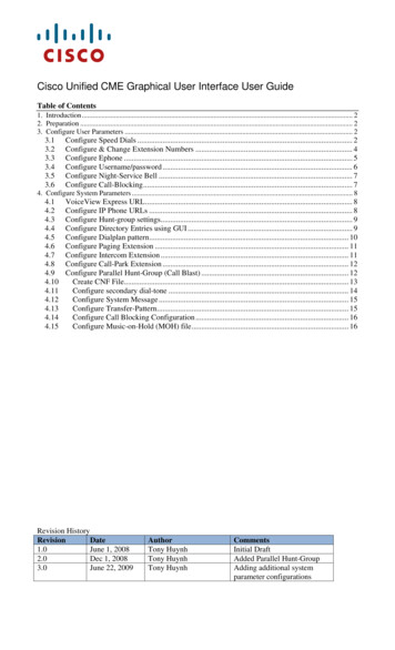
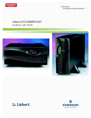
DISCONTINUEDPRODUCTLiebert GXT2-6000RTL630 User Manual - 208 / 240 VACAC PowerFor Business-Critical Continuity
DISCONTINUEDPRODUCT
TABLE OF CONTENTSIMPORTANT SAFETY INSTRUCTIONS . . . . . . . . . . . . . . . . . . . . . . . . . . . . . . . . . . . . . . . . . .1GLOSSARY OF SYMBOLS . . . . . . . . . . . . . . . . . . . . . . . . . . . . . . . . . . . . . . . . . . . . . . . . . . . . . . .31.0INTRODUCTION . . . . . . . . . . . . . . . . . . . . . . . . . . . . . . . . . . . . . . . . . . . . . . . . . . . . . . . . . .42.0SYSTEM DESCRIPTION . . . . . . . . . . . . . . . . . . . . . . . . . . . . . . . . . . . . . . . . . . . . . . . . . . . .52.1Transient Voltage Surge Suppression (TVSS) and EMI/RFI Filters. . . . . . . . . . . . . . . . . . . . 52.2Rectifier/Power Factor Correction (PFC) Circuit . . . . . . . . . . . . . . . . . . . . . . . . . . . . . . . . . . . 52.3Inverter . . . . . . . . . . . . . . . . . . . . . . . . . . . . . . . . . . . . . . . . . . . . . . . . . . . . . . . . . . . . . . . . . . . . 52.4Battery Charger . . . . . . . . . . . . . . . . . . . . . . . . . . . . . . . . . . . . . . . . . . . . . . . . . . . . . . . . . . . . . 52.5DC-to-DC Converter . . . . . . . . . . . . . . . . . . . . . . . . . . . . . . . . . . . . . . . . . . . . . . . . . . . . . . . . . . 62.6Battery . . . . . . . . . . . . . . . . . . . . . . . . . . . . . . . . . . . . . . . . . . . . . . . . . . . . . . . . . . . . . . . . . . . . 62.7Dynamic Bypass . . . . . . . . . . . . . . . . . . . . . . . . . . . . . . . . . . . . . . . . . . . . . . . . . . . . . . . . . . . . . 63.0MAJOR COMPONENTS . . . . . . . . . . . . . . . . . . . . . . . . . . . . . . . . . . . . . . . . . . . . . . . . . . . .73.1Main Frame and Electronics . . . . . . . . . . . . . . . . . . . . . . . . . . . . . . . . . . . . . . . . . . . . . . . . . . . 73.2Internal Battery Packs. . . . . . . . . . . . . . . . . . . . . . . . . . . . . . . . . . . . . . . . . . . . . . . . . . . . . . . . 83.3Removable Power Distribution Box. . . . . . . . . . . . . . . . . . . . . . . . . . . . . . . . . . . . . . . . . . . . . . 94.0WHAT’S INCLUDED . . . . . . . . . . . . . . . . . . . . . . . . . . . . . . . . . . . . . . . . . . . . . . . . . . . . . . 105.0INSTALLATION AND CONFIGURATION . . . . . . . . . . . . . . . . . . . . . . . . . . . . . . . . . . . . . . . . . 115.1Install the Main Cabinet . . . . . . . . . . . . . . . . . . . . . . . . . . . . . . . . . . . . . . . . . . . . . . . . . . . . . 115.1.15.1.25.1.3Tower UPS Installation . . . . . . . . . . . . . . . . . . . . . . . . . . . . . . . . . . . . . . . . . . . . . . . . . . . . . . . 11Rack-Mount UPS Installation . . . . . . . . . . . . . . . . . . . . . . . . . . . . . . . . . . . . . . . . . . . . . . . . . . 12Installing the Adjustable Rack-Mount Kit—Sold Separately . . . . . . . . . . . . . . . . . . . . . . . . . 125.2Install the Internal Batteries . . . . . . . . . . . . . . . . . . . . . . . . . . . . . . . . . . . . . . . . . . . . . . . . . 145.3Connect the Internal Batteries Using the External Connector . . . . . . . . . . . . . . . . . . . . . . . 155.3.15.4Storage . . . . . . . . . . . . . . . . . . . . . . . . . . . . . . . . . . . . . . . . . . . . . . . . . . . . . . . . . . . . . . . . . . . . 15Connect Input/Output Power. . . . . . . . . . . . . . . . . . . . . . . . . . . . . . . . . . . . . . . . . . . . . . . . . . 155.4.15.4.2Attach Power Distribution Box . . . . . . . . . . . . . . . . . . . . . . . . . . . . . . . . . . . . . . . . . . . . . . . . . 16Distribution Box Electrical Connections . . . . . . . . . . . . . . . . . . . . . . . . . . . . . . . . . . . . . . . . . . 175.5External Battery Cabinet Installation . . . . . . . . . . . . . . . . . . . . . . . . . . . . . . . . . . . . . . . . . . 186.0INITIAL START-UP AND ELECTRICAL CHECKS . . . . . . . . . . . . . . . . . . . . . . . . . . . . . . . . . . 197.0CONFIGURATION PROGRAM . . . . . . . . . . . . . . . . . . . . . . . . . . . . . . . . . . . . . . . . . . . . . . . 207.1GXT2-6000RTL630 Configuration Program Features . . . . . . . . . . . . . . . . . . . . . . . . . . . . . . 207.1.1What You Will Need . . . . . . . . . . . . . . . . . . . . . . . . . . . . . . . . . . . . . . . . . . . . . . . . . . . . . . . . . . 208.0CONTROLS AND INDICATORS. . . . . . . . . . . . . . . . . . . . . . . . . . . . . . . . . . . . . . . . . . . . . . . 218.1ON/Alarm Silence/Manual Battery Test Button . . . . . . . . . . . . . . . . . . . . . . . . . . . . . . . . . . 218.2Standby/Manual Bypass Button . . . . . . . . . . . . . . . . . . . . . . . . . . . . . . . . . . . . . . . . . . . . . . . 218.3Load Level Indicators (4 Green, 1 Amber) . . . . . . . . . . . . . . . . . . . . . . . . . . . . . . . . . . . . . . . 228.4Battery Level Indicators (5 Green) . . . . . . . . . . . . . . . . . . . . . . . . . . . . . . . . . . . . . . . . . . . . . 228.5Fault Indicator LED (Red) . . . . . . . . . . . . . . . . . . . . . . . . . . . . . . . . . . . . . . . . . . . . . . . . . . . . 22iDISCONTINUEDPRODUCT
8.6Bypass Indicator LED (Amber) . . . . . . . . . . . . . . . . . . . . . . . . . . . . . . . . . . . . . . . . . . . . . . . . 228.7UPS ON Indicator LED (Green) . . . . . . . . . . . . . . . . . . . . . . . . . . . . . . . . . . . . . . . . . . . . . . . 228.8Battery Indicator LED (Amber). . . . . . . . . . . . . . . . . . . . . . . . . . . . . . . . . . . . . . . . . . . . . . . . 228.9AC Input Indicator LED (Green) . . . . . . . . . . . . . . . . . . . . . . . . . . . . . . . . . . . . . . . . . . . . . . . 229.0OPERATING INSTRUCTIONS . . . . . . . . . . . . . . . . . . . . . . . . . . . . . . . . . . . . . . . . . . . . . . . . 239.1Normal Mode Operation. . . . . . . . . . . . . . . . . . . . . . . . . . . . . . . . . . . . . . . . . . . . . . . . . . . . . . 239.2Battery Mode Operation . . . . . . . . . . . . . . . . . . . . . . . . . . . . . . . . . . . . . . . . . . . . . . . . . . . . . 239.3Bypass Mode Operation . . . . . . . . . . . . . . . . . . . . . . . . . . . . . . . . . . . . . . . . . . . . . . . . . . . . . . 239.4Battery Recharge Mode . . . . . . . . . . . . . . . . . . . . . . . . . . . . . . . . . . . . . . . . . . . . . . . . . . . . . . 2310.0COMMUNICATIONS . . . . . . . . . . . . . . . . . . . . . . . . . . . . . . . . . . . . . . . . . . . . . . . . . . . . . . 2410.1Communications Interface Port. . . . . . . . . . . . . . . . . . . . . . . . . . . . . . . . . . . . . . . . . . . . . . . . 2410.2Pin 4 - Remote Shutdown on Battery . . . . . . . . . . . . . . . . . . . . . . . . . . . . . . . . . . . . . . . . . . . 2410.3UPS Intelligent Communications . . . . . . . . . . . . . . . . . . . . . . . . . . . . . . . . . . . . . . . . . . . . . . 2510.4Remote Emergency Power Off . . . . . . . . . . . . . . . . . . . . . . . . . . . . . . . . . . . . . . . . . . . . . . . . . 2611.0MAINTENANCE . . . . . . . . . . . . . . . . . . . . . . . . . . . . . . . . . . . . . . . . . . . . . . . . . . . . . . . . . 2711.1Internal Battery . . . . . . . . . . . . . . . . . . . . . . . . . . . . . . . . . . . . . . . . . . . . . . . . . . . . . . . . . . . . 2711.1.1 Internal Battery Replacement . . . . . . . . . . . . . . . . . . . . . . . . . . . . . . . . . . . . . . . . . . . . . . . . . 2811.2AC Power Connections . . . . . . . . . . . . . . . . . . . . . . . . . . . . . . . . . . . . . . . . . . . . . . . . . . . . . . . 2911.2.1 Disconnect . . . . . . . . . . . . . . . . . . . . . . . . . . . . . . . . . . . . . . . . . . . . . . . . . . . . . . . . . . . . . . . . . . 2911.2.2 Reconnect . . . . . . . . . . . . . . . . . . . . . . . . . . . . . . . . . . . . . . . . . . . . . . . . . . . . . . . . . . . . . . . . . . 3012.0TROUBLESHOOTING . . . . . . . . . . . . . . . . . . . . . . . . . . . . . . . . . . . . . . . . . . . . . . . . . . . . . 3112.0.1 Auto-Learning Battery Run Times . . . . . . . . . . . . . . . . . . . . . . . . . . . . . . . . . . . . . . . . . . . . . . 3513.0SPECIFICATIONS . . . . . . . . . . . . . . . . . . . . . . . . . . . . . . . . . . . . . . . . . . . . . . . . . . . . . . . .36FIGURESFigure 1Figure 2Figure 3Figure 4Figure 5Figure 6Figure 7Figure 8GXT2-6000RTL630, front view . . . . . . . . . . . . . . . . . . . . . . . . . . . . . . . . . . . . . . . . . . . . . . . . . . . . . 7GXT2-6000RTL630, rear view . . . . . . . . . . . . . . . . . . . . . . . . . . . . . . . . . . . . . . . . . . . . . . . . . . . . . . 8Internal battery pack with connector . . . . . . . . . . . . . . . . . . . . . . . . . . . . . . . . . . . . . . . . . . . . . . . . 9Optional power distribution—PD-L630 . . . . . . . . . . . . . . . . . . . . . . . . . . . . . . . . . . . . . . . . . . . . . . . 9Tower-use support bases, spacers for external battery cabinets . . . . . . . . . . . . . . . . . . . . . . . . . . 11PD-L630 power distribution box . . . . . . . . . . . . . . . . . . . . . . . . . . . . . . . . . . . . . . . . . . . . . . . . . . . 16PD-L630 power distribution box electrical connections diagram. . . . . . . . . . . . . . . . . . . . . . . . . . 17Power distribution box, PD-L630 . . . . . . . . . . . . . . . . . . . . . . . . . . . . . . . . . . . . . . . . . . . . . . . . . . . 29TABLESTable 1Table 2Table 3Table 4Table 5Table 6Table 7Table 8Table 9DB-9 pin assignment . . . . . . . . . . . . . . . . . . . . . . . . . . . . . . . . . . . . . . . . . . . . . . . . . . . . . . . . . . . .Indicator meanings . . . . . . . . . . . . . . . . . . . . . . . . . . . . . . . . . . . . . . . . . . . . . . . . . . . . . . . . . . . . . .Troubleshooting guide . . . . . . . . . . . . . . . . . . . . . . . . . . . . . . . . . . . . . . . . . . . . . . . . . . . . . . . . . . .Alarm conditions . . . . . . . . . . . . . . . . . . . . . . . . . . . . . . . . . . . . . . . . . . . . . . . . . . . . . . . . . . . . . . . .Battery run times . . . . . . . . . . . . . . . . . . . . . . . . . . . . . . . . . . . . . . . . . . . . . . . . . . . . . . . . . . . . . . .UPS specifications. . . . . . . . . . . . . . . . . . . . . . . . . . . . . . . . . . . . . . . . . . . . . . . . . . . . . . . . . . . . . . .Internal battery specifications . . . . . . . . . . . . . . . . . . . . . . . . . . . . . . . . . . . . . . . . . . . . . . . . . . . . .Output distribution specifications . . . . . . . . . . . . . . . . . . . . . . . . . . . . . . . . . . . . . . . . . . . . . . . . . .External battery cabinet specifications . . . . . . . . . . . . . . . . . . . . . . . . . . . . . . . . . . . . . . . . . . . . . .iiDISCONTINUEDPRODUCT243132333436373738
IMPORTANT SAFETY INSTRUCTIONSSAVE THESE INSTRUCTIONS!WARNINGOpening or removing the cover may expose you to lethal voltages within this unit even whenit is apparently not operating and the input wiring is disconnected from the electrical source.Observe all cautions and warnings in this manual. Failure to do so may result in seriousinjury or death. Refer all UPS and battery service to qualified service personnel. Do notattempt to service this product yourself. Never work alone.SAVE THESE INSTRUCTIONSThis manual contains important safety instructions. Read all safety, installation and operatinginstructions before operating the Uninterruptible Power Supply (UPS). Adhere to all warnings on theunit and in this manual. Follow all operating and user instructions. Individuals without previoustraining can install and operate this equipment.It is not intended for use with life support and other designated critical devices. Maximum load mustnot exceed that shown on the UPS rating label. The UPS is designed for data processing equipment. Ifuncertain, consult your local dealer or Liebert representative.This UPS is designed for use on a properly grounded (earthed), 208, 220, 230 or 240 VAC, 50Hz or60Hz supply. The factory default setting is 208VAC, 60Hz. Installation instructions and warningnotices are located in this manual.This UPS is for use only with a three-wire input: L1, L2, G.Electromagnetic CompatibilityThe GXT2-6000RTL630 Series complies with the limits for a CLASS A DIGITAL DEVICE, PURSUANT TO Part 15 of FCC rules. Operation is subject to the following two conditions: (1) This devicemay not cause harmful interference and (2) this device must accept any interference received, including interference that may cause undesired operation. Operating this device in a residential area islikely to cause harmful interference that users must correct at their own expense.Operate the UPS in an indoor environment only in an ambient temperature range of 32 F to 104 F(0 C to 40 C). Install it in a clean environment, free from conductive contaminants, moisture, flammable liquids, gases and corrosive substances.This UPS contains no user serviceable parts except the internal battery pack. The Off/Bypass pushbutton does not electrically isolate internal parts. Under no circumstances attempt to gain accessinternally other than to replace the batteries due to risk of electric shock or burn. Do not continue touse the UPS if the front panel indications are not in accordance with these operating instructions or ifthe UPS performance alters in use. Refer all faults to your local dealer, Liebert representative or theLiebert Worldwide Support Group.Servicing of batteries should be performed or supervised by personnel knowledgeable of batteries andthe required precautions. Keep unauthorized personnel away from the batteries. PROPER DISPOSAL OF BATTERIES IS REQUIRED. REFER TO YOUR LOCAL LAWS AND REGULATIONSFOR BATTERY DISPOSAL REQUIREMENTS.Never block or insert any object into the ventilation holes or other openings of the UPS.DO NOT CONNECT equipment that could overload the UPS or demand half-wave rectification fromthe UPS, for example: electric drills, vacuum cleaners, laser printers, hair dryers or any other appliance using half-wave rectification.Storing magnetic media on top of the UPS may result in data loss or corruption.Turn
AC Power For Business-Critical Continuity Liebert GXT2-6000RTL630 User Manual - 208 / 240 VAC ˆˇ ˆ ˇ
