Transcription
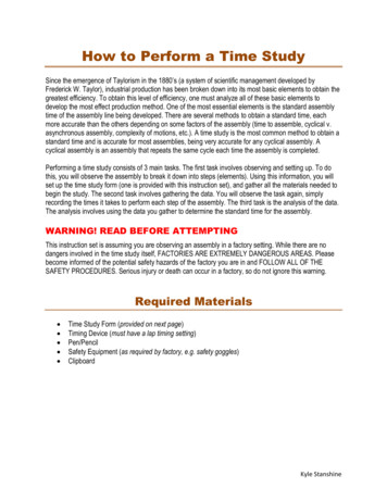
ROBOT ASSEMBLY OF AUTOMOBILE REAR AXLESIntroductionand General ApproachThis paper summarizes a study of rear axles made to determinethe feasibility of automating all or part of their finalassembly. This is a disguised version of a study made for anautomobile manufacturer in the middle 1980s.The automationproject was not implemented. The axle is illustrated in Figure1. The project involved all aspects of assembly, both technicaland economic, includingassembly operationsassembly system design and floor layoutmaterial flow timing and workstation timingrobots, tooling, and controlsparts handling and conveyinginterface to management systemsinvestment cost estimates and financialjustificationscomputer simulations, transport studies, andthroughput studiessuggestions for redesigns to improve automatibilityThe project began with a statement of the client's objectivesfor the product, dealing with model mix, production volume andcost projections, quality issues, and the desire to learn moreabout assembly automation. The feasibility of automatingassembly depends on the product's design and the difficulty ofindividual part mates. Engineering analyses based on partmating theory were used to predict difficult mates, which oftenarise from close clearances and tolerance stackups, includingrobot, jig, and gripper errors. Many alternate assemblysequences were considered, since these alternatives heavilyaffect final system layout, cost, tolerances, jig and gripsurfaces, deployment of people where necessary, and so on.Several redesigns and robot lab experiments were suggested toreduce assembly risk or make several operations feasible forautomatic assembly.1
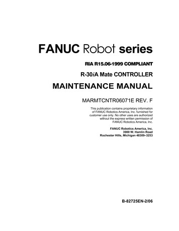
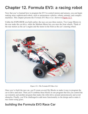
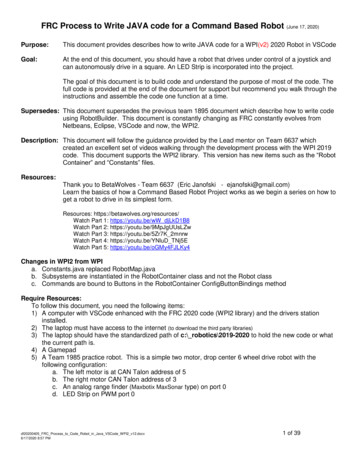
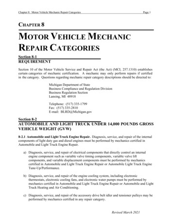
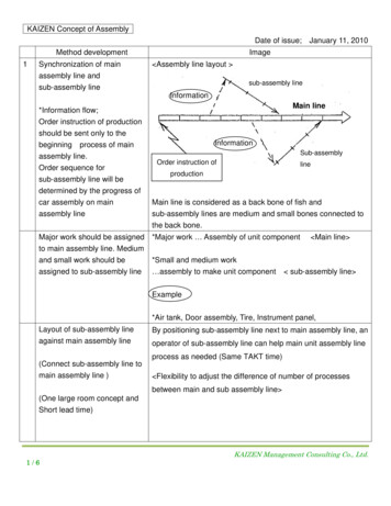
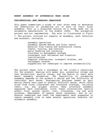
Figure 1. Photo of Rear AxleCandidate assembly sequences were then paired with possibleassembly technologies, including fixed automation, robots andpeople. These were analyzed by computer simulation and economicjustification programs to determine good candidate systems forpresentation to the client.Vendors were consulted concerningfeasibility and cost for various robots, tools, and transportoptions. A final list of options and recommendations waspresented, along with our recommendations.Characteristicsof the Rear AxleIn the case of the rear axle, options for redesign werelimited. This is a mature product, well tested in the field.Several options for redesign were generated and remaincandidates for future use. These deal with difficult mates thatare presently deemed unsuitable for robots or automaticmachines: removal and replacement of the shaft pin bolt (SPB)which retains the pinion shaft in the differential, andinsertion and coiling of the emergency brake cables. In eachcase, solution of the problem would involve cooperation withother departments in the plant or with vendors. In the absenceof any changes, this study assumed retention of the presentdesign. Figure 2 shows the parts and the assembly constraints.Figure 3 shows the feasible assembly sequences.2
MCIKEL GCHGA FDBBDJJPARTSA CARRIER ASSYB BACKING PLATEC SHAFTD BRAKE DRUM AND T'NUTE WITHDRAWN PINION SHAFT & SPBF INSERTED"""G (PUSH IN SHAFT & ) C-WASHER & PUSH SHAFT OUTH OILI COVERJ BRAKE CABLE, COILEDPRECEDENCE RELATIONSK FINAL PRESS TEST2 1L AIR TEST PLUG5 4M FIRST PRESS TEST1&2&6 55 711 810 912 1012 113 1&4&57 109 11(some can be combinedor simplified)Figure 2. Axle Parts and Assembly Constraints3LIAISONS1 C TO A2 B TO A3 J TO B4 D TO C5 G TO C6 E TO A7 F TO A8 L TO A9 I TO A10 H TO A11 K TO A12 M TO A
23643620665111114665217661 2 3 45 6 7 89 1011 12LIAISONKEY781119101112541312111DONEFigure 3. Diagram of Feasible Assembly Sequences4
Two other aspects of the product affect the feasibility ofautomation, namely the accuracy of the parts and the method ofpresenting them to the assembly system. In several instances,the probability of unsuccessful part mating is increased byparts that are out of tolerance or have missing or damagedchamfers. Several surfaces on axle shafts have such problems,as do the ends of axle tubes. The inside of side gears in thespline area may also be a problem. As is typical in suchsituations, assembly workers have learned to overcome theseproblems, but automated systems are not yet that smart. Thetooling and part mating recommendations seek to overcome theseproblems, but it is generally advisable to correct them wherethey occur.An additional quality problem concerns split axle tubes. Suchsplits are discovered at various stages of manufacture,including final pressure test. Since the last places suchsplits could occur are early in assembly -- either where tubesare joined to the central gear case or during bearing insertion-- we recommended an extra air test just after these operationsand before any additional value is added.Because redesign was not a major feature of this study, theemphasis fell on designing part mating methods, tooling tosupport part mating, determining assembly sequences, choosingassembly and transport technology options, combining optionsinto assembly systems, designing floor layouts, and analyzingthe candidate systems for economic and technical feasibility. Amajor study point concerned material transport options and partprovisioning. AGV's were compared to inverted monorailstechnically and economically, including counting how manyvehicles were needed. For AGV's, both dedicated and taxi modeswere simulated. The interface between fabrication and assembly,which occurs at the kitting area, was also examined carefullyto determine feasible alternatives. These include structureddunnage ("dunnage" refers to either disposable or reused partscarriers, baskets, boxes, etc.), simple vision systems, andbetter parts handling in the fabrication areas.We took as a starting point a preliminary system design andfloor layout created by the client. This design was refined asto task definitions and times, using the client's standard timedata, and was used as a baseline for comparison to designs theauthors generated. All these designs used the same database ofcandidate task times and equipment costs, even though differentassembly sequences and equipment choices were tried.The candidate systems are similar in most respects to systemswe are aware of around the world, although the most ambitiousones undoubtedly were preceded by thorough redesign of theproduct. The public literature includes information on VW'sHall 54 for automated final car assembly and engine dressing,FIAT's Termoli, Italy engine assembly plant, and recent GM5
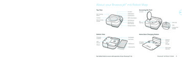
developments on engine assembly and cockpit installation. Atvarious points, these systems include AGV's, vision systems,tool changing robots, two or three robots at one station,robot-borne cluster head nut runners, a mix of people andautomation in the same system, and so on. Completely unmannedassembly is a goal in some cases. This is not readily attainedwithout extensive redesign. The added cost of redesigned parts,if any, must be compared to the expected savings, such asreliability of the system, product quality, cost growthcontrol, and so on.Part Mating IssuesEvery part mate involved in axle final assembly was emblysequences, or have other impacts on the final assembly system.These include backing plates, axle shafts, bearings, C-washers,and brake drums. Some part quality issues are listed in Table 1 .Each operation will be discussed in turn. Figure 4, Figure 5, andFigure 6 summarize the issues in the final recommended assemblysequence.Major PartsInsertion of bearings, seals and backing plate studs isrecommended to be done by fixed automation. These stations willaddress one axle at a time on a power/free conveyor. To ensuresuccess of these operations, care must be taken to provide thechamfers on the ID of tube ends that show on the print. Thesechamfers have been observed on many sample tubes to be of awide range of sizes, including nonexistent. Such stations mustbe adjusted slightly up or down to accommodate differentdiameter tubes resting in the same conveyor chocks. Referencingthe insertion tool to the top of the tube is a way to do this.6
PART QUALITY ISSUESOLERANCES:SHAFT FLANGE RUNOUT W R T SHAFT AXISJIGGING POINTS FOR TUBE-CASE ASSEMBLYNTERMITTENT CHAMFERS:SHAFT BUTTONSHAFT HUBSHAFT C-WASHER GROOVETUBE ENDBACKING PLATE FLANGE (FINESS WITH TOOL DESIGN)PINION SHAFT ENDS (A PROBLEM REGARDLESS OF WHETHER PIN COMES ALL THE WAYOUT OR NOTT IS CRUCIAL TO MAKE PARTS TO PRINT OR TO REVISE PRINTSBEFORE GOING OUT FOR FIRM BIDTable 1 Part QualityAssembly of backing plates is influenced by presence orabsence of a chamfer on the pilot diameter of the flange. Atooling concept is suggested that uses the tube itself as thepilot. (See Figure 7.) The success of this tool depends on an ODchamfer on the end of the tube. The tool concept takesadvantage of the fact that the ID of the backing plate is acarefully held dimension. This tool first picks up 4 nuts from4 feeder slides, then picks up the backing plate by the ID andholds it magnetically. The tool slides over the end of the tubeon its OD and pushes on until it butts against the pilotdiameter of the flange. The nut runner in the tool advances andforces the backing plate off the magnets and onto the pilotdiameter, meanwhile driving the nuts home.Assembly of axle shafts into tubes is the riskiest part mate.A heavy part must be cantilevered and inserted into a hole sothat the tip of the axle will go into a second hole 24" to 36"inside the tube. The gripper must grasp the shaft on the flangeface and OD. A tolerance stackup analysis including lateral andangular errors due to robot, jigging, gripping, and both axleand shaft fabrication shows that this mate could failfrequently.We recommended several alternate shaft insertion strategies.Some involve sensing the location of the shaft tip after it isgripped. Others involve utilizing a two or three phaseinsertion method in which the shaft is put most of the way in,then released so as to let it fall to a standard stableposition in the tube, then regripped for final insertion intothe side gear's spline.7
Even if tolerance issues on axle shafts are resolved,successful mating of axles and side gears may require robotson each side to work together,twisting the shafts. This wouldensure that there is relative rotation between shaft ends andthe gears. People on the line use this strategy now. If it isnecessary, it would make infeasible the line layout in theclient's baseline system, which had only one robot at eachstation.Brake cables present serious assembly difficulties. They areawkward, and both ends must be dealt with at different timesduring assembly. Based on current methods, the cable surroundsthe brake drum. The drum must be put on after one end of thecable is installed and before the other end is hooked to ashaft stud. The last operation seems unavoidably manual,forcing one of two alternatives: if brake drum installation isautomated, two people are needed at the end of the line just tohook cables to studs; or brake drum installation is manual andthe same person hooks the cables. The former leads to poor linebalance, so the latter has been chosen even though brake druminsertion is apparently an easy robot task.If brake cables are inserted into backing plates after theplates are attached to the axle assemblies, then the insertionof brakePARTASSY METHODFEEDINGMETHODBACKINGPLATE BOLTS,BEARINGS,SEALS,GREASEROBOT OR FIXEDAUTOMATION(FIXED AUTOPREFERRED)HOPPER ORBOWLBRAKE CABLESGRIPSURFACEINSIDE DIAM.TOOL PRESSESON O.D.TOLERANCESSUM OF CHAMFERSNEEDSTHE CHAMFERS,MAYBE A LITTLELUBETYP /- 0.04"-0.06"MANUALFIRST AIR TESTFIXED AUTOBACKING PLATEROBOT OR F.A.IMPORTANT FORCYCLE TIME THATNUTS BE DRIVENBY SAME TOOLAT SAME TIME.PRECOILEDOR LOOSEN/AAS REQ'DN/AAXLE PAN-FACEDOWNREGISTER ONPAN FACE &TUBE ENDSNOT DIFFICULTID--ALSOSQUEEZE/CENTERBRAKESHOESCHAMFERS ON TOOLMEET CHAMFERS ONTUBE ENDSKIT ONPALLET.COULD USESTRUCTUREDDUNNAGE& VISION TOSKIP KITTING.B.P.TUBECHAMFERS ON TOOLNUTDRIVERTOOLREQUIRES CAREFULDESIGN, PLUS GOODQUALITY TUBESCHAMFERS. ALSOALIGNMENT OFBOLT HOLESVISION ORSTRUCTUREDDUNNAGECSDLFigure 4 Part Feeding, Assembly, and Tooling Summary--18
PARTAXLE SHAFTSASSY METHODROBOTFEEDINGMETHODGRIPSURFACEKIT ONPALLET.COULD USESTRUCTUREDDUNNAGE& VISION TOSKIP KITTING.FLANGE FACE& FLANGE O.D.BUTTON CHAMFER TOCASE CHAMFER POSUNCERTAINTY AXLETOLERANCES: LIKELYSOURCE OF TROUBLE!BUTTON CHAMFER ISUSUALLY MISSING.EXPERIMENTS.PROBABLY ASSYMETHOD USING ASENSOR OR REGRIP AFTER SHAFTIS FAR IN TUBE.PART QUALITYIS AN ISSUE.FOR AUTOMATIC ASSY,SLOT CHAMFERS WOULDHELP. A PART QUALITYISSUE.LITTLE IF PEOPLEPUT THEM IN.C-WASHERSPEOPLE OR ROBOT.(PEOPLE PREFERRED)CURRENT TOOLSCOULD USE IMPROVEMENT.CHUTE ORLOOSEAS DONE NOWSPB ANDPINION SHAFTPEOPLE OR ROBOT.(PEOPLE PREFERRED)N/AAS DONE NOWBRAKE DRUMSPEOPLE, ROBOTS,OR FIXED AUTO.IMPORTANT FORCYCLE TIME THATTINN NUT BE PUTON AT SAME TIMEBY SAME TOOL.KIT ONPALLET.COULD USESTRUCTUREDDUNNAGE& VISION TOSKIP KITTING.O. D. AND CARRIERSIDE OF RIM.TOLERANCESN/A /- 0.0625"I.E., NOT DIFFICULTAS LONG AS AXLESREALLY HAVE THEIRCHAMFERS. A PARTQUALITY ISSUE.NEEDSA REDESIGN IFROBOTS WEREDESIREDCHAMFERS ON SHAFTENDS.COORDINATIONWITH ROBOT/TOOLON OTHER AXLE TOROTATE TO GETSTUDS INTO HOLES.CSDLFigure 5. Part Feeding, Assembly, and Tooling Summary-2cables is much easier if the axles are oriented pan face down,although they must be pan-face up for several other operations.When we were considering automating C-washer insertion, wethought of designing tooling that would operate from below. Adropped C-washer would fall out harmlessly. Even oil fill couldin principle be done with the pan face down if the cover wereput on first (again from below) and the drain hole used forfill. While these options have some appeal, they havedisadvantages that caused them to be dropped.Another alternative is to attach cables to backing platesbefore mating plates to axle assemblies. The client or itsvendor could do this. The problem is that the cables dangleawkwardly from the plates and the axle, making automatichandling risky. Cables could snag or could be pinched infixtures. These problems also exist if we utilize an alternateassembly sequence in which backing plates are installed rightafter the bearings and seals. These operations can easily occurpan-face down. Backing plate attachment could be manual orautomatic, and brake cable installation could occur rightafter. When the axles are transferred to pallets they could beturned pan-face up and would stay that way throughout the restof the operations. Pallets that permit axle rotation andpeople's time to rotate them would not be needed.9
In short, additional attention needs to be paid to brakecables, including pre-coiling them and devising a better way totie off the loose ends prior to painting and shipment to thevehicle assembly plant. Several major advantages would begained, including redeployment of people away from robots,saving of some people, and avoidance of turning assemblies 180otwice.PARTOIL FILLRTVCOVER & BOLTSRATIO TAGFINAL AIR TESTASSY METHODROBOT CARRIESFILL TUBEROBOT APPLIES TOPAN FACE OR TOCOVER. PAN FACEPREFERRED TO AIDBOLT-COVER KITTING.ROBOT WITH BOLTDRIVER IN GRIPPERSIMULT. WITH BOLTSROBOT CARRIES TOOL.IMPORTANT FORCYCLE TIME THATPLUG IS PUT IN BYSAME TOOL RIGHTAFTER TEST.FEEDINGMETHODGRIPSURFACEAS NOWN/ATOLERANCESNOT DIFFICULTNEEDSPOSITIVE SHUTOFFAND NOZZLE WIPERTO PREVENT DRIPSSO PANFACE DOESNOT NEED WIPING.AS NOWREGISTER TOOL ONPAN FACE ANDTOOLING RECESSESNOT DIFFICULTCLEAN PAN FACEKIT/FEEDBOLTS TOCOVER FIRST.RIM OF COVERREGISTER TOOL ONPAN FACE ANDTOOLING RECESSES /- 0.05"I.E., NOT DIFFICULTCARE PROGRAMMINGROBOT SO BOLTSDON'T FLOP OUTNOT LIKELY TO BEA PROBLEM.KIT WITHBOLTSN/AN/ASADDLE ON TUBESAME AS BOLTTHIS PART IS APROBLEM. REPLACEWITH LASER MARKING ON CASE.NOT DIFFICULT. ALITTLE REDESIGNON THE PLUGWOULD HELP.WOULD BE GOOD TOSTANDARDIZETEST HOLE LOCATIONON ALL MODELS.CSDLFigure 6 Part Feeding, Assembly, and Tooling Summary-3Automated insertion of C-washers is probably feasible, butthis task, too, is surrounded by manual tasks, namely removaland reinsertion of the SPB. Only replacement of the SPB byanother pinion shaft retention method would make automatic Cwasher insertion useful. Several redesigns have been suggested,of which the most promising is replacement of the SPB by a rollpin.10
12TUBEGRIPPER SLEEVEGRIPPER SLEEVETUBEFLANGEMAGNETMAGNETNUTRUNNERNUT RUNNERBACKING PLATE34GRIPPER SLEEVENUT RUNNERCSDLFigure 7. Detail of Backing Plate Gripper. The gripperoperates in four steps. 1. The gripper holds the backingplate with the magnets while approaching the flange. 2.It advances and lands on the tube flange opening usingits own chamfer. 3. The nut runners advance, pushing thebacking plate off the tool onto the pilot diameter onthe flange. Then they tighten the nuts. 4. The toolleaves.A lot of additional work would have to be devoted to thesematters before suitable alternatives emerged. The reward wouldbe large, however, since, together with brake cables, the Cwasher operations account for all of the people that thebaseline and recommended systems contain within the roboticpart of the line.The ratio tag is an awkward part, hard to feed, easy to lose.It should be replaced with some other marking method, such aslaser barcode marking. As discussed below, the bar code couldinclude model and date/time information and could be used bythe production control system to coordinate launching of kitsor loading them to pallets.Other Parts and Tasks11
In general, other parts do not present great difficulties. Nutscan be fed down chutes to nut runners while they are in toolstorage. Serrated backing plate studs can be similarly fed forautomatic insertion into flanges on tubes. Bearings and sealscan be magazine fed, packed that way by the vendors. Covers canbe stacked for easy robot pickup by magnetic or vacuum grip andturned under a bolt dispenser prior to assembly. C-washers canbe fed down chutes for people or automatic tools to pick upmagnetically. Air test hole plugs can be bowl fed.Robotic pickup of kitted shafts, backing plates, and, ifapplicable, brake drums can be aided by attention to kittolerances and gripper design. Simple vision systems abovepallets or on grippers might be needed to take out grippinguncertainty, or grippers could be designed with wide enoughthrow and attention to closure motions so that parts aregripped correctly even if they are a bit off location in thekit. Such methods might eventually allow automatic kitting,depending on how much it costs to obtain good structureddunnage.Part QualityIt was noted above that some parts are not made as specified bythe prints. This may not affect axle performance but couldcause problems for assembly machine vendors. Either the partsshould be made to print or else a set of "as built" printsshould be prepared for issue to the vendors. This will helpensure that tools, grippers, and fixtures are designed to asaccurate specifications as possible, reducing the risk ofrework and delay in getting the assembly system operating atfull capacity.From a management point of view, one should strive for thelevel of quality that the product or the assembly system needs.The assembly system will "inspect" the parts and probably jamon ones that are too far out of tolerance. From an economicpoint of view, one must remember that the parts presentlyaccount for about 93% of an axle's in-plant cost, and finalassembly accounts for only about 7%. Efforts to improve partquality could cost too much. Quality for quality's sake isjustifiable only on the grounds that a spirit of quality willinevitably result in better axles, even if one cannot preciselytrace specific warranty reductions or other benefits tospecific investments. A spirit of quality could eliminate manypoor practices that management could be unaware of.Summary of Part Mating IssuesInstallation of backing plates, brake cables, and the C-washersconfronted us with several assembly sequence and automationproblems. These were resolved via line balancing and ons.12
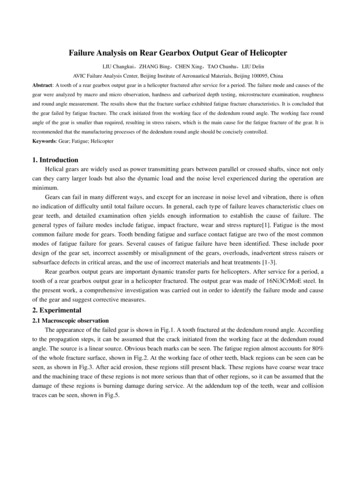
Installation of axle shafts, backing plates, and brake drumspresent some risks associated with part quality. Experimentswere recommended to reduce these risks, and specific partquality improvements were recommended.Tooling, Jigs, Fixtures, and WorkstationsThis section covers design of pallets, kits, and robotworkstations. These designs require a decision as to how manyaxles will be on a pallet. Later discussions will justify achoice of 4 axles per pallet, based on economics and systemtiming.Pallet design must conform to access needs of people, robots,and kits. For economy, one pallet design should be used for allaxle models. A suitable design places the axles on about 33"centers, leaving about 17" for a walk-in space to help a personreach the differential. See Figure 8. If longer pallets are usedto create more space between axles, rotational type robots willhave difficulty reaching all 4 axles to insert shafts. (Typicalrobots in this class include the Cincinnati Milacron T3 767 orthe GMF S 360R, each with about 100" reach and 150# payload.KUKA, ASEA, and Toshiba make similar robots.) If space forpeople is a problem, the robot can be mounted on a linear axisalong side the pallet at an extra cost of 20K to 30K andabout 3 seconds per move. Then a longer pallet can be used.Other access difficulties arise because of the unusable spacearound the center of the robot. The latter has typically a 36"to 45" radius. The unusable space problem is not solved bymounting the robot upside down. It is eased, however, by usingthe powered linear axis parallel to the pallet.Only one rotational robot could be found that could insert axleshafts and also reach the differentials with 4 axles perpallet. For assembly sequence and throughput reasons, however,no systems were designed that combined end-of-tube and centerof-axle operations at the same station.An alternative to rotational robots would be gantries. Theirreach is essentially unlimited. However, they are typicallyabout twice as expensive as rotational robots. They wererecommended only where their reach is essential.We recommended that all reach estimates be confirmed by fullscale 3 dimensional CAD simulations or actual mockups. Theabove studies used scale 2 dimensional CAD heirliterature. Such regions may shrink when different wrist onfigurations may occur while putting in axles or backingplates. Only the Cincinnati Milacron "3 roll wrist" may be13
immune to such problems. See Figure 9 for a typical robot reachanalysis, of which about 25 were done for this study.116.5"x 74"14"29"17"20"33"12"CSDLFigure 8. Assembly Pallet with Four Axles on It.The speed and repeatability of suitable rotational robotsappears adequate for the axle's tasks. Typical GMF S 360R tasktimes, observed from video tapes at conferences, support ourassumption of a 15 second cycle time, plus about 3 seconds toreach from one axle to the next on the pallet. A 15 second toolchange time allowance is probably more than enough, especiallyif tools are centrally located near the pallet. Experiments toverify task times are particularly important because so much ofthe system design depends on timing and line balance.14
14"17"29"20"33"34"UNREACHABLE ZONE116"12"85" MEDIUM ASEAMODEL74"OUTLINE OFSMALL AXLES111" LARGE ASEAMODELCSDLFigure 9. Reach Analysis for an ASEA Robot and Palletwith Four AxlesThese robots have about 0.02"-0.05" repeatability. To avoidoscillations when carrying heavy tools and parts, they cannotbe run at full speed. Better dynamic control algorithms areneeded. Repeatability itself may or may not be payload or warmup dependent. Experiments are needed to determine this. Tocompensate for repeatability and other errors (jigging, partfabrication, gripping), chamfers must be provided on grippers,grip surfaces of parts, and the entry faces of mating parts.These chamfers must sum to dimensions larger than the largestof contemplated errors. Chamfer sums exceeding twice the RMSerror would provide good reliability, although space on someparts and tools of the axle, particularly the backing plate, donot permit this luxury. To reduce contact forces during matingin the presence of error, it was recommended that tools containengineered compliances such as Remote Center Compliances.In the recommended system, the axles must be turned over 180o.It was assumed that pallets could be designed to permit this.An additional requirement is that one pallet do for all axlemodels. A design that permits this involves placing the axle15
tubes on chocks so that the turned center countersink on theinput drive shaft is in the same XY location (parallel to thepallet surface) for all models. This center may be accessed bya center point that is spring loaded in the Z (vertical)direction.Because different axles have different tube diameters, theabove design will place the tube centerlines at differentheights with respect to the pallet. It is assumed that robotprograms can be adjusted automatically to compensate for this.(Other, larger program changes must be made as well, such as toaccommodate different tube and shaft lengths.) It was assumedthat pallets would have machine-readable codes on them thatsignal the robot as to which program to use.In our design, a parts kit would contain the axle shafts,backing plates, and brake drums for one axle assembly. Itappears feasible to mount a kit of parts for each axle rightnext to and below it on the pallet. Kits would be approximately6' long by 14" wide, and would go on the pallet before theaxles do. To conserve space, brake drums and backing platescould be mounted upright rather than flat. This approachcontrasts to the client's baseline, in which a kit containedparts for 4 axles, and was placed on top of the pallet afteraxles were loaded. This sequence requires the kit dunnage to beremoved part way through assembly, requiring an extra robot.See Figure 10 for possible layouts of kits on the work pallet.All other parts are kitted or supplied in bulk to the line atthe point where they are used. This includes fasteners, covers,bearings, seals, grease, RTV, and brake cables. Delivery couldbe via lift truck, AGV's or special pallets that pass throughthe assembly stations untouched.16
b ackin gp lat eaccesshole forC washersb rake dr umparts on kit palletaxle tubebrake drumb ackin gp lat ebaking pl.b rake dr umalternate parts storageparts on work pallet12"KIT PALLETFigure 10 . Options for Kitting Parts17
Assembly System DesignAssembly system design has six main aspects: capacity planning,equipment choice, assignment of tasks to equipment, transportchoice, floor layout, and kitting. These interact heavily, andthere are many alternatives. We identified several cases worthstudying deeply. Computer synthesis, analysis, and simulationtools played a large role in the design. Table 2 lists thealternatives studied.Capacity PlanningTwo choices for production rate were available, 140 hours/weekas specified by the client's baseline system, and 88hours/week. The former requires 10 hour rolling shifts by theemployees, who find themselves with "weekends" in the middle ofsome weeks. They also work both daytime and nighttime in thecourse of a three-week period. Current labor agreements providesubstantial wage supplements for time over 8 hours per day,time over 40 hours per week, and weekend time. Average employeecost per hour is 26 vs. 24 for 88 hours per week. This wagedifference is largely responsible for the ultimate conclusionthat 88 hour/wk systems are usually more economical. Thisconclusion survives the fact that more equipment is needed formost of the 88 hour/wk systems to support their higherproduction rate. As this conclusion began to emerge, wecurtailed study of 140 hour/wk systems; economic analyses wereconducted on both, but only 88 hour/wk systems were simulatedin detail.Capacity is influenced by several factors:the speed of individual workstationstime lost while robots change toolstime lost while people or robots shift attentionfrom one axle on a pallet to the nexttime lost shifting from one pallet to another orwaiting while transport takes a pallet away andbrings anotherRobot tool changing is needed only if a robot is given morethan one task and different tools are needed for some of them.Shifting from one axle to another arises if several axles areon a pallet vs. only one. Finally, time is lost shiftingbetween pallets due to their size; lost time can be reduced bydouble-buffering pallets at stations, although this requirespurchase of additional pallets. Transport type also affectspallet shift time, with AGV's assumed to be slower thanconveyors unless double buffering is used. (Double bufferinginvolves providing two work locations for a robot; the robotworks at one while transport brings a new pallet to the other.This technique works well for stations with one robot but isalmost impossible to arrange at stations with one robot on each18
MODELING (S,E,F)*AIR TEST LATEAIR TEST EARLYAUTO LOAD OF MHSMANUAL LOAD OF MHSMANUAL C-W ASHERSAUTO C-WASHERSAUTO BRAKE DRUMMANUAL BRAKE DRUMROBOTIC SEALSFIXED INSTALL SEALS2 AXLES/PALLET4 AXLES/PALLETKIT AFTER LOADKIT BEFORE LOADSERIALPARALL ELside of a work area. Two robots may be needed for cooperativework to mate axle shafts, for example.)CONFIGURATION NAMECLEINT'S ORIGINAL PROPOSALMODIFIED CLIENT'S PROPOSALSALTERNATIVE #1 **SALTERNATIVE #2ALTERNATIVE #3FALTERNATIVE #2.1AALTERNATIVE #2.1BSFALTERNATIVE #2.3SEFALTERNATIVE #2.6 (CLUSTER)"BASELINE" SYSTEMSEFSERIAL CONVEYOR SYSTEME* S SIMULATED, E ECONOMIC ANALYSIS, F FLOOR PLAN* * DOES NOT INCLUDE BRAKE CABLE OR SPB REMOVAL OPERATIONSTa
for the product, dealing with model mix, production volume and cost projections, quality issues, and the desire to learn more about assembly automation. The feasibility of automating assembly depends on the product's design and the difficulty of