Transcription
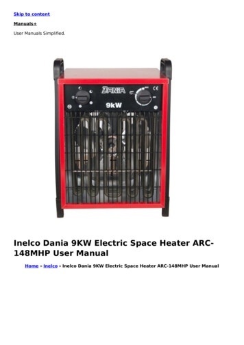
OPERATION & INSTALLATIONMANUALBAPTISTRY HEATER AND CONTROL SYSTEM(120V/208-240V)BES60005T 11KW Shown AboveBES6000 & BES6000T SERIES 5.5KWBES6005 & BES6005T SERIES 11.0KW510A N. SHERIDAN ST. – CORONA, CA 92880
TABLE OF CONTENTSFITTINGS INCLUDED2IMPORTANT SAFETY INSTRUCTIONS3PRODUCT FEATURES6INSTALLATION/OPERATING CONSIDERATIONS7ELECTRICAL INSTALLATION7COMPONENT CONNECTIONS10SYSTEM INTERFACE MODULE11PLUMBING TIPS12HOLE DRILLING DIAGRAM13PRESSURE SWITCH PLUMBING DIAGRAM14EQUIPMENT DESCRIPTION15START UP16OPERATION18PROBLEM SOLVING21SYSTEM DATA LABEL / WARRANTY22HYDROQUIP CONTROL/HEATER ASSEMBLIES & OPTIONS COVERED IN THIS MANUALHQ PART -0042-K11KW HEATER SYSTEM5.5KW HEATER SYSTEM11KW HEATER SYSTEM W/TIMER5.5KW HEATER SYSTEM W/TIMERWATER FILL/LEVEL KIT (FLOAT)WATER FILL/LEVEL KIT (PSI SWITCH)DRAIN CONTROL KITREMOTE CONTROL KITWATER LEVEL ASSY. (FLOAT)WATER LEVEL ASSY. (PSI SWITCH)WATER FILL ASSY.SYSTEM INTERFACE MODULE1
IMPORTANT SAFETY INSTRUCTIONS2
WHEN INSTALLING AND USING THIS EQUIPMENT, BASIC SAFETY PRECAUTIONS SHOULD ALWAYSBE FOLLOWED, INCLUDING THE FOLLOWING:READ AND FOLLOW ALL INSTRUCTIONSINSTALLATION CONSIDERATIONS1. A bonding lug has been provided on the outside of the equipment system electrical controls box. This lugpermits the connection of a No. 8 AWG solid copper bonding conductor between the equipment systemand all other electrical equipment and exposed metal in the vicinity, as may be needed to comply withlocal regulations.2. The equipment system must be installed to provide adequate drainage, and to prevent water fromentering the electrical equipment area. When installing the equipment system indoors, the floors andstructures beneath the installation area must be protected against water run off.3. The electrical supply for permanently connected equipment systems that do not have an internaldisconnect must include a suitably rated switch or circuit breaker to open all ungrounded supplyconductors to comply with section 422-20 of the (NEC) National electric code, ANSI/NFPA 70-1987. Thedisconnect means must be readily accessible to the tub occupant but at least 5 feet (1.5m) from the tubwater. The electrical supply for permanently connected equipment systems must also include a suitablyrated ground fault circuit interrupter (GFCI) to comply with article 680-42 of the national electric code,ANSI/NFPA 70.4. DANGER - RISK OF ELECTRIC SHOCK. Do not permit any electrical such as a light, telephone, radio,or television, within 5 feet of the tub.5. DANGER - to reduce the risk of injury, do not permit children to use this product unless closelysupervised at all times.6. WARNING - RISK OF CHILD DROWNING. Exercise extreme caution to prevent unauthorized access bychildren. To avoid accidents, ensure that children cannot use the tub unless they are closely supervisedat all times.3
7. WARNING - TO REDUCE THE RISK OF INJURYA. The water in a tub should never exceed 100F (38C). Before entering the tub the user shouldmeasure the water temperature with an accurate thermometer, since the tolerance of watertemperature-regulating devices may vary as much as /- 5F (3C). A water temperatures of 100F(38C) is considered safe for a healthy adult. Lower water temperatures are recommended forextended use (exceeding 10-15 minutes) and for young children.B. Since excessive water temperatures have a high potential for causing fetal damage during the earlymonths of pregnancy, pregnant or possibly pregnant women should limit tub water temperatures to100F (38C).C. The use of alcohol, drugs, or medication before or during tub use may lead to unconsciousness withthe possibility of drowning.D. Persons suffering from obesity or with a medical history of heart disease, low or high blood pressureshould consult a physician before using a hot tub.E. Persons using medication should consult a physician before using a hot tub since some medicationmay induce drowsiness while other medication may affect heart rate, blood pressure, and circulation.F. Because occasional users of the tub may not be aware of all of the potential risks associated with tubusage, they should be made aware of these important safety features.G. The very young, or aged, those with illness, heart conditions or under doctor’s care should not usethe tub unattended. Infants should not be permitted in water temperatures more than 100F.H. Prolonged immersion in water that is warmer than normal body temperature can result in a dangerouscondition known as HYPERTHERMIA. The causes, symptoms, and effects of hyperthermia may bedescribed as follows: hyperthermia occurs when the internal temperature of the body reaches a levelseveral degrees above the normal body temperature of 98.6F. The symptoms of hyperthermiainclude dizziness, fainting, drowsiness, lethargy, and an increase in the internal body temperature.The effects of hyperthermia include: (1) unawareness of impending hazard, (2) failure to perceiveheat, (3) failure to recognize the need to exit the hot tub, (4) physical inability to exit the hot tub, (5)fetal damage in pregnant women, and (6) unconsciousness resulting in a danger of drowning.WARNING: the use of alcohol, drugs, or medication can greatly increase the risk of fatalhyperthermia.8. DANGER - to reduce the risk of injury to persons in the tub, never remove, or alter in any way, the gratesor covers on the suction fittings in the tub. Never operate the equipment system if the grates or covers onthe suction fittings are broken or missing.The water should always flow freely from the hydrotherapy jets within the tub. Any blockage or restrictionof water flow by persons or objects may damage the system components, create an electrical shockhazard, and/or cause water damage to the surrounding area. To avoid damage to the pump and heater,the equipment system must never be operated unless the tub is filled with water to the operating level.4
9. WARNING - the equipment system may be equipped with a ground fault circuit interrupter (GFCI),mounted on the electrical control box. This GFCI protects against electrical shock hazard by sensingelectrical fault conditions and interrupting the electric power applied to the equipment system.Before each use of the tub the GFCI, if provided, should be tested in the following manner: Turn electricpower on, Push the test button. The reset button should pop outward, indicating that the GFCI isfunctioning properly. Push the reset button all the way in, restoring electrical power to the equipmentsystem. If the reset button does not pop outward when the test button is pushed, a loss of GFCIprotection is indicated. Should this occur, immediately disconnect electrical power from the equipmentsystem, and discontinue use of the tub until a qualified technician has identified and corrected theproblem.10. DANGER - risk of electrical shock. Install at least 5 feet (1.5m) from all metal surfaces. A tub may beinstalled within 5 feet of metal surfaces if each metal surface is permanently connected by a solid copperconductor attached to the wire connector on the control box that is provided for this purpose. A pressurewire connector is provided on the control box to permit connection of a minimum No. 8 AWG (8.4mm)solid copper bonding conductor. The bonding conductor should not be smaller the service conductorssupplying the equipment. Connect this point to any metal enclosures of electrical equipment, metal waterpipes, or conduit within 5 feet (1.5m) of the unit as needed to comply with local requirements.SAVE THESE INSTRUCTIONS5
PRODUCT FEATURES1.GROUND FAULT CIRCUIT INTERRUPTER – This device is required for portable tubs as specified in the national electrical codearticle 680. The GFCI is designed to protect against potential electrical shock hazard should a ground fault occur.Note: Equipment mounted GFCI discontinued as of June 14, 20142.THERMOSTAT - The thermostat regulates the water temperature of your tub.3.TIME CLOCK (Optional) - Provides timer control over heating and filtering cycles4.PUMP RECEPTACLE – Connect pump here.5.POWER AIR SWITCH – Turns the system on and off6.SAFETY LIGHT CIRCUIT – 120V hot output for 12V light kit (PT# 37-0029-SM)7.SANITIZER CIRCUIT – Provides a 120V output when pump is running for a water sanitizer8.HIGH LIMIT - A safety switch that will shut the heater off if the temperature within the heater reaches a non-adjustable limit.9.SYSTEM INTERFACE MODULE RECEPTACLE – Provides Auto-Fill and Auto-Drain function. Auto-Fill Control (PT# 48-0042-K)10. REMOTE CONTROL RECEPTACLE: Provide remote thermostat control over the system.11. HEATER ASSEMBLY - Thermostatically controlled and equipped with a high-limit safety shut off.12. ROCKER SWITCH - Determines operation of the time clock.13. PLUMBING HEADER ASSEMBLY – Connects the pump to the heater (Plumbing for BES6000/T Systems may appear different).14. PLUMBING HEADER ASSEMBLY – Connects the bottom heater to the top heater (BES6005/T Systems Only).15. BOOSTER HEATER – Additional 5.5KW Heater Assembly Included with the BES6005/T Systems Only.16. PUMP ASSEMBLY – Circulates water from and to the baptistery. (Not self priming)17. BASE – ABS base for mounting equipmentFigure 1.06
INSTALLATION AND OPERATING CONSIDERATIONSThe equipment control system must be protected from the elements by installing it indoors or in a weathertight enclosure.The equipment should be installed so that there is safe and adequate access for servicing and routinemaintenance procedures.The single-speed circulation pump included with this system is NOT a self-priming pump and must beinstalled below water level for proper operation.Connections between the tub and equipment control system should include shut off valves for servicing andonly non-metallic pipe should be used.Connections between the tub and equipment should be done with schedule 40 and/or flexible PVC.If any thread sealer compounds are to be used, they must be compatible with PVC and ABS plastics.Equipment room or enclosure must have adequate ventilation.Note: Operation of your tub during the warm months of the year may cause the temperatures to rise insidethe equipment compartment. Due to the extensive insulation of some models it may cause the pumpsthermal protection device to automatically turn the pump off for a short period of time (15-30 minutes) to allowthe pump to cool down before automatically restarting. This cool down feature will not harm your system butserves to protect the pump from damage. This condition can also be caused by low voltage or by highaltitudes where the air necessary for cooling is much thinner.ELECTRICAL INSTALLATIONA qualified electrician must make all electrical connections to the equipment control box in accordance withthe National Electrical Code and in accordance with any local electrical codes in effect at the time ofinstallation. All electrical connections must be made in accordance with the wiring information contained inthis manual, or on the back of the field wiring access panel of the equipment control box.The electrical supply for permanently connected equipment controls must also include a suitably rated groundfault circuit interrupter (GFCI) to comply with article 680-42 of the National Electrical Code, ANSI/NFPA 70.The equipment may be designed to operate at 208-240 volts, 60hz. Connections must be made using copperconductors only. Field provided conductors and circuit breakers or fuses must be sized to accommodate thetotal amperage load of the equipment.WARNING - Improper electrical connections or conductor sizing will create the potential for an electricalhazard, and may void the warranty.ModelBES-6005/TBES-6000/THeater VoltageHeater Watts208-240 V120V/208-240V11.0 kW5.5 kWBreaker SizeWire60-80A20A/40-50A43/4CAUTION: Use only approved pressure-type wire splicing or connectors suitable for the size and type ofwiring used.The electrical supply for this product must include a suitably rated switch or circuit breaker to open allungrounded supply conductors to comply with section 422-20 of the National Electrical Code, ANSI/NFPA 70.The disconnecting device must be within sight, and readily accessible to the user of the tub, but installed atleast 5 feet (1.5m) from the tub. Connect a # 8 AWG (8.4mm) solid copper bonding conductor between theequipment control box bonding lug and all other electrical equipment and exposed metal in the vicinity, asmay be needed to comply with local regulation.7
GFCI WIRING DETAILThe GFCI required for this system must be compatible with 4-wire service.It is important that the GFCI circuit breaker is installed correctly. Often this component has been improperlyinstalled causing the breaker to instantly trip when the system is turned on. Below is an illustration of a typicalGFCI breaker installation.WARNING - Refer to the circuit breaker manufacturers installation instructions. This illustration is meant to bea guide for Field Technicians and is not intended to override or substitute the instructions supplied with thecircuit breaker.8
208/240 VOLT INSTALLATION - Permanently Connected Units1. Remove the faceplate from the control box to allow access to the input wiring.2. Connect input wiring to the terminal block as shown below. A GFCI protected three wire electrical serviceplus ground is required for a 208-240-volt connection (line 1, line 2, neutral, and ground). Failure toconnect a neutral line will cause the control box to malfunction and may void the warranty.3. Reinstall the control box faceplate.BES6000/6000TBES6005/6005TOPTIONAL 120 VOLT INSTALLATION - Permanently Connected Units**ONLY APPLICABLE ON THE BES 6000/T (5.5KW) SYSTEM**1.2.3.Remove the faceplate from the control box to allow access to the input wiring.Connect input wiring to the terminal block as shown below. A two wire electrical service plus ground is requiredfor a 120-volt connection (line 1, neutral, and ground). Place a 14awg minimum jumper wire between Neutraland Line 2 at the incoming terminal block. **Heater will not operate without this jumper**Reinstall the control box faceplate9
BES OPTIONAL COMPONENT CONNECTIONS10
SYSTEM INTERFACE MODULESEE PAGE 12 FOR IMPORTANT TIPS11
PLUMBING AND AUTO-FILL TIPSPLUMBING TIPS: MEASURE TWICE DRILL ONCE DRY-FIT PLUMBING BEFORE HOLES ARE DRILLED SCHEDULE 40 AND/OR FLEXIBLE PVC SHOULD BE USEDBETWEEN EQUIPMENT AND BAPTISTRY ALWAYS USE COMPATIBLE ADHESIVES AND PRIMERSNOTE: IF ANY THREAD SEALER COMPOUNDS ARE TO BE USED,THEY MUST BE COMPATIBLE WITH PVC AND ABS PLASTICS.AUTO-FILL VALVE TIPS: INSTALL PER PLUMBING DIAGRAM VALVE ASSY CAN BE AFFECTED BY WEIGHT, SUPPORT IFNECESSARY FILL ASSY CAN BE PLUMBED VERTICALLY OR HORIZONTALLY TO BYPASS FILL VALVE LOOSEN SMALL BLACK SCREW NEXTTO SOLENOIDAUTO-DRAIN VALVE TIPS: IF SYSTEM IS DRAINING AND FILLING AT THE SAME TIME FLIPTOGGLE SWITCH ON DRAIN VALVE TO OPPOSITE POSITION DO NOT ATTEMPT TO TURN VALVE BY HAND, PERMANENTDAMAGE WILL OCCUR.BALL VALVE INSTALLATION / TIPS BALL VALVES HAVE BEEN PROVIDED FOR CONVENIENCESHOULD SERVICE NEED TO BE PERFORMED. INSTALL (1) VALVE BEFORE AND (1) VALVE AFTER THECONTROL SYSTEM AS SHOWN ON PAGE 14.12
HOLE DRILLING DIAGRAMNote: Sealing compounds must be compatible with PVC and ABS plastics13
Note: These drawings and information are for general presentation purposes only. The drawings are not intended as adiagram for installation.Note: Sealing compounds must be compatible with PVC and ABS plastics14
EQUIPMENT DESCRIPTIONBES6000/T (5.5kW)BES6005/T (11kW)WIDTH 27”HEIGTH 13”DEPTH 15”WIDTH 29”HEIGTH 13”DEPTH 15”CONTROL BOXThe control box contains all the electrical components necessary to operate your tub, it also contains the fieldwiring compartment. The System Interface Module (DRAIN/FILL CONTROL) Control plugs into thereceptacle on the side of the control box.GROUND FAULT CIRCUIT INTERRUPTER (GFCI)Note: Equipment mounted GFCI discontinued as of June 14, 2014The GFCI is designed to provide protection against potential electrical shock hazard should a ground faultoccur.The installation of a properly sized ground circuit and bonding circuit is still required as detailed in theelectrical installation section of this manual. The GFCI in your installation may be installed at the electricalservice panel, a separate sub panel, or built into the control box.Test the GFCI before each use and at least monthly when the tub is not being used regularly.Test the GFCI as follows:1. With the power on, push the test button; the lever should trip to center position.15
Caution - If the GFCI fails to operate in this manner, do not use the tub until a qualified service technician hascorrected the problem.1. To restore power, flip lever to the OFF position and back to ON.THERMOSTATSetting the thermostat controls the temperature of the water. The thermostat is located on the front of thecontrol box.When the equipment is operating, the thermostat will control the heater. Initially, adjust the thermostat knobto the middle of the “Comfort Zone.” This setting will cause the water temperature to rise to approximately 80F(27C). Do not expect to feel hot water coming from the return fitting.The length of time it takes the water to reach desired temperature depends on several factors: watertemperature at start, ambient air temperature, tub capacity, relative humidity, type and insulating qualities of acover and the consistency of electric power applied.Any graduations on the scale around the thermostat are intended for reference only. They do not reflect theactual water temperature. Remember that a small change on the dial will yield a difference of severaldegrees, so make small adjustments until you find your preferred temperature. Allow several hours betweenadjustments for temperatures to stabilize. Use an accurate thermometer to monitor the water temperature.HIGH LIMITThe purpose of this switch is to shut off the heater if the water temperature within the heater reaches afactory-set, non-adjustable limit. After the water cools sufficiently, push to reset. If the switch trips repeatedly,do not use the tub until the problem has been identified and corrected by a qualified service technician.HEATERThe stainless steel housing contains an electrical heating element and is fitted with a safety pressure switchthat monitors water RTHERMOSTATThe heater operates on demand at the power levels indicated in the table below. It will shut off when thethermostat setting is reached or the water ceases to flow.16
SYSTEM INTERFACE & MODULEProvides functionality of Auto-Fill & Auto-Drain option(s) and components when module is installed.SYSTEM DIAGNOSTIC CENTERThese indicators provide real time diagnostics of the system. HEATER “ON” – Illuminated whenever the heater is activatedPUMP “ON” – Illuminated whenever the system pump is activated.SYSTEM FUSE – Illuminated when the main system fuse is blowno Possible indication of pump issue.HIGH LIMIT TRIPPED – Illuminated when the High-Limit safety switch is trippedo If the switch trips repeatedly do not use until corrective service is performedSYSTEM MIS-WIRE – Illuminated when the system has been mis-wiredo This is an indication the 120V has been sent up the Neutral line and is a protective feature.Have an electrician correct the issue to allow operation.TIME CLOCK (IF EQUIPPED)7 DAY TIMECLOCKProvides timer control over heating and filtration cycles. To activate a timed cycle push the teeth on the timeroutward, each tooth represents 2 hours of operation. The (2) modes of operation are based on the rockerswitch under the timer and are as follows:1. Timed Heat Mode: The system heats and filters based on the setting of the timer2. Thermostatic Heat Mode: The pump comes on and off with relation to the thermostat. If
system data label / warranty 22 hydroquip control/heater assemblies & options covered in this manual hq part number description control systems bes-6005 11kw heater system bes-6000 5.5kw heater system bes-6005t 11kw heater system w/timer bes-6000t 5.5kw heater
