Transcription
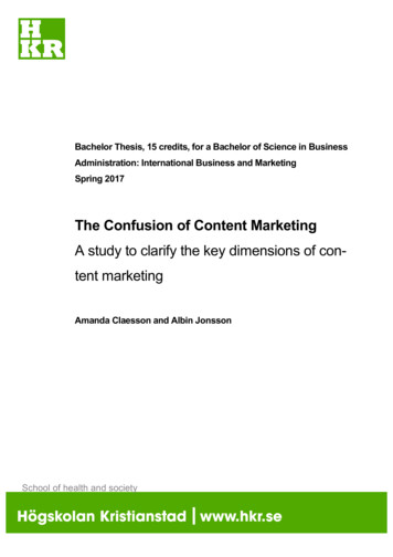
Lifting body design and CFD analysis of a novellong range pentacopter, the TILT LR droneDesign och CFD analys av lyftgenererande ytor för "the TILTLR drone",en ny drönare med fem propellrar för lång räckviddDaniel Cagatay & Haoqian YuanMaster Thesis in Aerospace EngineeringDepartment of MechanicsStockholm, June 2016KTH Supervisor: Stefan WallinIndustrial supervisor: Pau MallolIn collaboration with Inkonova AB, Go Virtual Nordic AB
MASTER THESIS IN AEROSPACE ENGINEERINGLifting body Design and CFD analysis of a novel long rangepentacopter,the TILT LR droneDaniel Cagatay & Haoqian YuanInkonova AB in collaboration withThe Royal Institute of Technology, Go Virtual Nordic ABDepartment of MechanicsAerospace engineering in the field of AeronauticsStockholm, 2016.06III
Lifting body Design and CFD analysis of a novel long range pentacopter,the TILT LR droneDaniel Cagatay & Haoqian YuanMaster’ Thesis 2016Department of MechanicsAerospace engineering in the field of AeronauticsInkonova AB, Go Virtual Nordic ABRoyal Institute of TechnologySE-114 28 Stockholm, SwedenTelephone: 46(0)70-06863 31, 46(0)73-67747 03Email: dcagatay@kth.se, haoqian@kth.seCover:The picture on the cover is the pressure distribution of the lifting body from a 3D simulation,where no rotors was involved. The picture describes the aerodynamic behavior of the surfaceduring a steady flight. The picture was produced in Paraview.Stockholm, 2016
ABSTRACTIn the thesis, a lifting body has been designed aiming to generate lift force for the pentacopter,called TILT LR (Long Range), at higher velocities during flights to improve the aerodynamicperformances. The configuration, which is used as the skeleton of the long range drone for upto 75 kilometers flights, is based upon a tilting system allowing the rotors to rotate around theirown axis in both pitch and roll angles. This offers the possibility to the TILT LR flying withoutany vertical excess thrust at a proper angle of attack and velocity. This new drone can be directlyapplied to missions require long flight time or cover long distance, such as Search & Rescue(SAR), power lines and off-shore structures inspection, fire monitoring or surveillance.Several main CAD models have been created during the process of design and presented in thereport together with the final design. For each model in the process, CFD simulations have beenapplied to observe the behaviors of the flows around the surfaces of the body during steadyflights, followed by a brief analysis for further modification. A series of simulations withvarying velocities and angle of attack have been performed for the final design, analyzing itsperformances under different air conditions. Flight envelope of the design has been presentedalso, together with some ideas of possible further studies on the pentacopter.Keyword: Lifting body, CFD, Mesh, Multi-rotor, Drone, Aerodynamic, Simulation,y-plus, Aspect ratioV
ACKNOWLEDGMENTSFirst of all, we would like to thank Inkonova for offering us the opportunity to perform thisthesis. They have supplied us with the information of the multi-rotor which the lifting surfaceis going to applied upon. It has been a great experience working with them. Particularly, wewould like to give our gratitude to Pau Mallol, for all the help during the entire process of thethesis.Go Virtual has been very helpful by offering us the CFD software in order to simulate themodels which were created. Faranggis Bagheri from Go Virtual has assisted us with the toolsthat have been used in the thesis. We would like to thank Metacomp Technologies andPointwise as well, the providers of the software programs that have been used and have alsoassisted us with the tools.Last but not the least, we would like to thank our supervisor, Stefan Wallin, at the Mechanicsdepartment of KTH for supplying us with the theory which the thesis is based upon, and all thesupport and advice during the entire thesis process.VII
CONTENTABSTRACTACKNOWLEDGEMENTSCONTENTVIIIX1. INTRODUCTION11.1 Background11.2 Description and goals11.3 Limitations and assumptions21.4 General process/methodology32. METHODOLOGY & THEORY2.1 Basic theory442.1.1 Aerodynamic theory of thin airfoil42.1.2 Computational Fluid Dynamics52.1.3 Boundary layer and flow separation52.1.4 𝑦 " theory62.1.5 Aspect ratio & Downwash effect82.2 Design parameterV112.2.1 Airfoil112.2.2 Configuration & Frame132.2.3 Rotors152.3 Simulation162.3.1 Model building162.3.2 Mesh16IX
2.3.3 Simulation192.3.4 Result analysis242.4 Result normalization253. RESULTS273.1 2D simulations273.2 3D simulations323.2.1 Aspect ratio effects323.2.2 Rotors343.2.3 Development of the models353.2.4 Final design433.3 Model with the central rotor494. CONCLUSION & DISCUSSION524.1 Flight envelope524.2 Further study of the thesis534.2.1 Winglet534.2.2 AT rotor choice544.2.3 Modification of the wings544.2.4 Interaction between the body and the central rotors554.2.5 Location of AT rotors564.2.6 Control surface565. REFERENCE58APPENDIX60
1. INTRODUCTIONIn this chapter, the background and a brief description of the thesis will be stated, togetherwith the limitations and assumption involved in the process. The general process of the thesiswill also be described.1.1 BackgroundThe developing technology has contributed to an increasing popularity of multirotor drones inboth commercial and industrial market in the recent years.[1] Due to this expansion of market,the practicability of drones becomes more and more essential, leading to the request forincrease on both the flight time and the flight distance of drones. To satisfy the growingdemand of more power efficient drone, the main attention so far has been put on thedevelopment of new high power batteries and the study of advanced motors or configurationswith more optimized power consumption. As for the frame of a drone, the strength is usuallyconsidered with a priority than the body aerodynamic properties from the point of safety andstability. Much speculation amongst the multirotor community about whether the bodyaerodynamics even really matters in multirotor drones can be found nowadays, since it isassumed that the drones were always flying so slow that the body aerodynamic forcesgenerated by the frame would be negligible.[2] Yet with the advent of new high power hybridlithium-iron and fuel cells batteries and high current/small size electronic speed controllers,multirotor drones are now able to fly faster than 100 kilometers per hour. This means thebody aerodynamic properties of the drone frames are unneglectable to the power efficiencyand might instead induce a significant improvement on the drone performance during flights.In this case, with the aerodynamic contribution from the body, missions covering a long rangeand requiring a long flight time, such as search & rescue, inspection of power lines and offshore inspection, can be achieved by drones, without costing too much human and materialresources.1.2 Description and goalsThe thesis would be performed against this background, showing how a lifting body of apentacopter, called TILT LR (Long Range), can be built to increase the flight time and flightdistance by using an aerodynamic surface to generate lift during 61
The basic concept is to create aerodynamic surfaces generating enough lift at medium to highspeeds that the drone can be maintained in the air without using excess vertical thrustprovided by the rotors during flights. Two kinds of rotors will be applied to the drone, namelythe central rotor, which would be mainly used to provide lift for hovering and flights at lowspeed, and the attitude rotors, which are mainly responsible for the necessary thrust toovercome the drag and provide the attitude during flight. The system applied in the drone is atilt rotor system, which means that the rotors can be altered in pitch and roll angles providingthe necessary thrust during the flights. For ideal cases, the rotors axial alignment would lie inthe direction of the motion, providing thrust only against the drag.The main goal of the thesis is to design the aerodynamic surfaces, or the lifting body to beprecise, for a drone aimed for long range missions, followed by CFD simulations to analyzeits performances during forward flights in steady states. The expected properties of theoutcome design are shown in Table 1.1Table 1.1 Expected properties of the designLift generated from the bodyAt least 70% of the take-off weight (TOW)Drag generated from the body20 – 40 % of the TOWMaximum dimensions, in millimeter1500*1200*300The thesis will be performed by simulating the design using CFD software to acquire theaerodynamic effects generated by the lifting surface. The design is targeting the applicationsin industrial market, such as supply delivery, maintenance of power lines, fire observation,surveillance on so on. Depending on the application, the expected outcome can be varying,which means the crucial variables might be altered to achieve the goal in each mission.1.3 Limitations and assumptionsAccording to the basic concept of the thesis, several limitations and assumptions are madeduring the design and analysis process: The dimensions of the drone are not flexible, which means the space available for thebody is restricted. No aeroelasticity phenomena, such as flutter and divergence, are to be considered in ,2016
The main focus of the thesis will be put on the aerodynamic properties only, which meansthe mechanic and electric constructions are not to be designed or analyzed. Only steady states will be considered for the simulation. All the results presented in the report will be normalized, which will be discussed later.1.4 General process/methodologyThe process designing and analyzing the lifting body up to the results requires four steps withseven programs involved, namely Onshape, SolidEdge, AutoCAD, Pointwise, CFD ,Paraview and Matlab.The first step is Model Building using Onshape/SolidEdge/AutoCAD. The first two programsare both CAD tools which are used to generate the 3D models of the lifting body and the thirdwas used for 2D cases mainly. The second step is Mesh using Pointwise, which is a meshgenerating tool, used to define where the flow around the body is to be directed. The CAD filecreated in the first step is imported to this program. The third step is Simulation using CFD ,which is a computational fluid dynamics program, being able to solve the flow velocity field,boundary layers and to calculate the flow generated forces for the lifting surface. The meshwhich is created in step two is imported to this program and the corresponding flow field issolved after the necessary inputs are inserted. The fourth step is Result Analysis usingParaview and Matlab, which are mainly for result presenting tool and calculation respectively.Detailed introduction of the process will be described in the next 163
2. METHODOLOGY & THEORYIn this chapter, all the theory involved in the thesis will be presented, including theaerodynamic theory considered during the design, the choices of the basic parameters as wellas the inputs and principles of all the software programs used in in the thesis.2.1 Basic theory2.1.1 Aerodynamics theory of thin airfoilFigure 2.1 Aerodynamic forces of airfoilThe aerodynamic forces are generated by the pressure differences and skin friction effectscaused by air flow all over the surfaces of the aircraft.[3] Forces of most concerns, namely lift𝐿 and drag 𝐷 , are the components of the resultant aerodynamic force perpendicular andparallel to the velocity vector, which satisfy𝐿 𝐹& sin 𝛼 𝐹, cos 𝛼(2.1)𝐷 𝐹& cos 𝛼 𝐹, sin 𝛼(2.2)according to Figure 2.1, where 𝛼 is the angle of attack. From aerodynamics theory, the forcessatisfy41𝐿 𝐶2 𝜌𝐴𝑈 62(2.3)1𝐷 𝐶7 𝜌𝐴𝑈 6
where 𝜌 is known as the density of the surrounding air, 𝐴 as the chord of airfoil for 2D casesand the area of wings for 3D cases, 𝑈 as the velocity of free stream. In the equations, 𝐶2 and𝐶7 are known as the lift and drag coefficient respectively, which have been generated byexperiments for a certain airfoil and can be found in the databases. Generally, the coefficientsof a specific airfoil can be expressed as𝐶2 𝐶2 𝛼, 𝑀 ,𝐶7 𝐶7 (𝛼, 𝑀, 𝑅𝑒)(2.5)where M is known as the Mach number, Re as the Reynold’s number whose influence on liftcoefficient is neglected in normal cases where Re is high and M is low.Eq. 2.3 and 2.4 only apply under the assumption of 2D cases or 3D cases with a wing ofinfinite length, which means 3D effects are not considered. Thus, the estimation made usingthe equations are not precise for 3D cases, which will be discussed in the following sectionsof this chapter.2.1.2 Computational Fluid DynamicsComputational Fluid Dynamics, known as CFD, is a branch of fluid mechanics usingnumerical analysis and algorithms to solve and analyze problems that involve fluid flow, heattransfer and associated phenomena such as chemical reactions. There are several approachesavailable depending on the specific situation that is needed to be solved, which generallyfollow the same procedure. The volume of interest is first defined by physical boundaries asthe computational domain. Then the fluid inside the volume is divided into discrete, nonoverlapping cell, which is usually named as the mesh. The development of the model to use isthe next step, where the equations of motion, turbulence model as well as the properties of thefluid are to be defined according to the conditions. Then the specifications of appropriateboundary conditions at cells which coincide with or touch the domain are to be made beforethe problem is finally solved iteratively as a steady-state or transient.[4]The technique is very powerful and widely used in all kind of industrial and non-industrialapplication areas, aerodynamics of aircraft and vehicles in particularity, which is the reasonthat CFD was the main method applied in the thesis.2.1.3 Boundary layer and flow separationAs a body moves relative to a fluid, the molecules of the fluid near the body are disturbed andmove around the body, where aerodynamic forces are generated. The molecules right next toRoyalInstituteofTechnology,MasterThesis,20165
the body surface would stick to the surface, due to the forces while the molecules just abovethe surface would slow down in their collisions with the molecules sticking to the surface.The effect of these collisions get weaker and weaker with the increase of the distance to thesurface, which means the velocity of the molecules get higher as they are farther away fromthe body until it gets to the velocity of free stream.[5] A thin layer is therefore created by thisbehavior of the fluid near the body, which is usually referred as boundary layer, as shown inFigure 2.2.Figure 2.2 Boundary layer and flow separation[6]In the boundary layer, viscous forces play an important part close to the body surfaceaffecting the behavior of the flow there. When the boundary layer travels far enough againstthe adverse pressure gradient, it detaches from the surface of the body forming eddies andvortices and flow separation occurs, as shown in Figure 2.2.2.1.4 𝑦 ? theoryFor a simulation with accurate result, a decent model of boundary layer is required. Aboundary layer is the part of flow next to solid surface in the air field, where viscous forcesplay a dominant part distorting the non-viscous flow. In the thesis, according to the industrialpurposes of the drone, the surrounding air condition is assumed to be turbulent, whichcontributes to a total turbulent boundary layer model. Consequently, a proper value of thedimensionless wall distance, namely 𝑦 ? , is required for modelling the influence of the viscousforces in a turbulent 6
Since the exact value of 𝑦 ? can only be calculated with the actual boundary layer built afterthe simulation, a decent estimation of the value is necessary during the meshing for the choiceof the first cell height, h. The dimensionless wall distance, which was first introduced byTheodore von Karman[7], can be expressed as𝑦? 𝑢A ℎ𝜈(2.6)In the equation above, 𝜈 is kinematic viscosity, while 𝑢A is the wall friction velocity𝑢A 𝜏E 𝜌𝜈 𝑈 ℎEGHH 𝑈1𝐶2 I(2.7)where U is the velocity of the air flow and 𝐶I is the friction coefficient. Combining all theequations above, the height of first cell can be determined as𝜈𝑦 ?ℎ 𝑈1𝐶2 I(2.9)According to empirical relations for boundary layers, friction coefficient can be expressed asP𝐶I 0.0296𝑅𝑒& OQ2(2.10)P𝐶I 0.332𝑅𝑒& O62(2.11)for turbulent layer andfor laminar layer. For different location on the surface, distance from the leading edge 𝑥 ischosen and therefore the corresponding Reynolds number of the location is𝑅𝑒& 𝑥𝑈𝜈(2.12)The relationship of the air flow velocity U, the dimensionless wall distance 𝑦 ? and the firstcell height h is described by Eq. 2.6 – 2.12, where it can be concluded that when U increases,if the quality of the boundary layer model is to be maintained meaning 𝑦 ? stays constant, hneeds to be reduced. Similarly, if the reference length x increases, h needs to be increased forRoyalInstituteofTechnology,MasterThesis,20167
a constant 𝑦 ? of the boundary layer model. This will be applied later for the choice of asuitable first cell height for 3D simulations after the study of 𝑦 ? have been done.Using Eq. 2.12 where x is chosen as the maximum length of the body and U as the referencevelocity, an estimation of Reynold’s number can be made for the simulations that would beperformed in the thesis. The Reynold’s number was estimated to be 580000 approximately,which is fairly low for an aircraft. This means that the state of the flow, namely laminar orturbulent, is difficult to be estimated and could be dependent on subtile difference. Since itwas almost impossible to determine when and where the transition from laminar boundary toturbulent would start on the body, the state of boundary was assumed to be totally turbulentfor all the simulations performed in the thesis, which would insert some error from the reality,but also was the best choice in the cases.2.1.5 Aspect ratio & Downwash effectFigure 2.3 Definition of the aspect ratioAs shown in Figure 2.3, for an airplane, the aspect ratio is defined as the ratio of its span s tothe aerodynamic breadth chord, which normally is not constant for most wings. In this case,the aspect ratio is defined as𝑠6𝐴𝑅 𝐴(2.13)where 𝐴 is the area of the wing.8RoyalInstituteofTechnology,MasterThesis,2016
For a real wing in three dimensions, there are many factors that might result in the differencebetween theoretical aerodynamics forces and the real ones, among which the so calleddownwash effect is of great significance. For lifting surfaces, the air pressure on the upperside is lower than the pressure below, along the span. Near the wing tips, the air is thereforedriven by the different pressures to move from the lower side to the upper side, resulting invortices during flights, as shown in Figure 2.4 and 2.5.Figure 2.4 Downwash effect from the top viewThe wing tip vortices produce a downwash of air behind the wings, which is very strong at thewing tips and decreases to the roots of the wings, inducing a downwash flow which decreasesthe effective angle of attack of the wings. The flow creates an additional, downstream-facingcomponent to the aerodynamic force acting all over the wings and induces an extra dragwhich is usually known as the ‘induced drag’. Additionally, since the lift is defined to beperpendicular to the local flow, the wing tip is at a lower effective angle of attack due to theinduced flow. Therefore, the lift coefficient at the tips is reduced after resolved and so iscoefficient of the entire wing is,20169
Figure 2.5 Wing tip vortices[9]In this case, by taking the aspect ratio 𝐴𝑅 and the free stream lift coefficient 𝐶HU , which isusually stated in the details of an airfoil into consideration, the final lift coefficient 𝐶H can beexpressed as𝐶H 𝐶HU𝐶1 HU𝜋𝐴𝑅(2.14)The induced drag coefficient then becomes𝐶H 6𝐶WX 𝜋𝐴𝑅𝑒(2.15)where 𝑒 is the efficiency factor and for wings with elliptic lift distribution 𝑒 1 whilegenerally 𝑒 1, and the final drag coefficient can be expressed as𝐶W 𝐶WX 𝐶WU(2.16)where 𝐶U is the free stream drag coefficient. These equations were mainly used during thedesign of the body for aerodynamic force estimations, where aspect ratio is hesis,2016
2.2 Design parameter2.2.1 AirfoilThe main idea of the design was to build a body, which was able to generate lift during flight,leading to the concept of airplanes, or wings to be precise. Therefore, a study of wing profilewas performed to find a suitable wing profile as the cross section of the body.Figure 2.6 Geometry of airfoil[10]Figure 2.6 presents the main geometry of a wing profile, where 𝑥I is the position of maximumcamber of its mean camber line and 𝑦I is its magnitude. According to the geometry of themean camber line, the wing profiles can be divided as follow. Symmetrical airfoilAn airfoil with zero maximum camber is called a symmetrical airfoil, as shown in Figure 2.7.Figure 2.7 Example of symmetric airfoil: NACA 0012With identical upper and lower surfaces, a wing with symmetric airfoil would generate no liftduring a flight at 0 angle of attack. Symmetrical airfoils are usually applied to rotary-wingsbecause they have almost no center of pressure travel, which leads to relatively constant 11
under varying angles of attack. Besides, symmetrical airfoils deliver acceptable performanceunder those alternating conditions, also with lower cost and ease of construction. However,less lift generated and relatively undesirable stall characteristics are the disadvantagescompared to nonsymmetrical airfoil.[11] Positive cambered airfoilNonsymmetrical airfoils with mean camber lines above the chord line are called positivecambered airfoil, as shown in Figure 2.8.Figure 2.8 Example of positive cambered airfoil section: GOE 383Positive lift will be generated during a flight for wings with positive cambered airfoils at 0 angle of attack. Negative cambered airfoilOppositely, nonsymmetrical airfoils with mean camber lines below the chord line are callednegative cambered airfoils, which will lead to negative ‘lift’ during a flight at 0 angle ofattack and therefore, negative cambered airfoils are usually not applied to general wings orrotary-wings.Nonsymmetrical airfoils normally have an increased lift-drag ratio together with better stallcharacteristics, which contributes to better maneuverability of the drone. The disadvantages,on the other hand, are that wings usually experience big center of pressure travels when theangles of attack were changed when twisting forces might occur on the wings. For the designin the thesis, the drone would be mainly controlled by the rotors which means themaneuverability is not as important as a decent lift–drag ratio. In this case, a positivecambered airfoil should be a good choice for the 016
There were 3 airfoil profiles taken into consideration during the different phases of the designprocess, which were NACA4415, GOE383 and NACA4412 and the plots of aerodynamiccoefficients are shown in Appendix I. NACA4415, which is a very common airfoil, was firstchosen as the cross section of the conceptual design due to its decent lift-drag ratio at lowangle of attack. GOE383 was than chosen for the next design, for its large maximumthickness which was useful to enclose the co-axial rotors at the center. The airfoil also has agood lift- drag ratio at low angle of attack. For the design, NACA4412 was chosen due itsbetter aerodynamic properties and the small maximum thickness, since the idea of enclosingthe central rotors was dropped.2.2.2 Configuration & FrameThe configuration of a drone defines how all the rotors are placed and connected to each otherand the main frame. The most common choices of configuration nowadays are shown inFigure 2.9, where the configuration of the design is supposed to be chosen. In the figure, themotors with double colors are co-axial rotors.Figure 2.9 Common configurations of a 01613
According to basic idea of the thesis, the following criterions were considered: Since the main lift to sustain the drone during the hovering will be mainly provided by apair of co-axial rotors located at the center of the drone. The attitude rotors, known as theAT rotors, are therefore responsible for the thrust during transient state, cruise anddirection turning mainly. For weight consideration, AT rotors inserted in the designshould not be more than 4 to achieve the lightest system as possible. Due to the industrial purpose of the drone, a camera or other optical equipment needs tobe able to be placed in the front of the drone, where enough space should be spared toprevent the propellers from obstructing the view. The drone is designed for long range missions mainly, which leads the efficiency ofpower to a priority. In this case, by comparing a tri-copter with a configuration of T3 anda quadcopter with X4, which fit the criterions above, materials show that with similar sizeand system, a tri-copter will be more efficient than a quadcopter (about 15%-25% roughly)if designed properly.[13],[14]After taken all the limitations into consideration, the initial frame of the body was given asFigure 2.10. Further modifications would be done according to the results of aerodynamicsimulations.Figure 2.10 Initial frame of the body with modified T3 configuration with central co-axial 16
2.2.3 RotorsAccording to the general idea, there are five rotors involved in the drone, including a pair ofco-axial rotors located at the center of the body, three AT rotors with two at the side and thethird behind the body, which are able to tilt, as shown in Figure 2.10.1) Central RotorsThe central rotors are mainly responsible to provide the lift required for the drone to sustain inthe air in a hover as well as a flight when necessary. Due to the restricted space for the centralrotors, a pair of large co-axial rotors are chosen. The lift that a pair of co-axial rotors are ableto provide up to 1.8 times larger when compared with a single disc rotor with the same sizepropeller, which is enough to cover the entire weight of the drone. In a hover, the two discsare counter-rotating, providing the same amount of torque yet also in the opposite directionwhich encounter each other and consequently the stability is ensured and can be also used toprovide yaw control.2) Attitude rotorsThe two AT rotors, tilting forward and backward aside the body, are mainly responsible forthe thrust of direction changing, forward acceleration and overcoming the drag during theflights. The other one located behind the body balancing the pitch and yaw moment of thedrone caused by the lifting body during flights. According to the limitation of drag, the thrustprovided by AT rotors is not necessary to be high, which means the efficiency should beconsidered with priority here to achieve a long flight 5
2.3 SimulationsSeveral simulations were done after the basic design parameters were chosen, following theprocess described in Chapter 1. Each simulation was started with the model building, thenmodel meshed and solved, and finally ended with the analysis of results, which will bediscussed in detail in the section.2.3.1 Model building —— AutoCAD & SolidEdge & OnshapeModel building involves three software programs, AutoCAD SolidEdge and Onshape, ofwhich the former two are provided by KTH and can be accessed freely by students. The thirdone is open-source online CAD software, which is very much like SolidEdge, yet lessfunctional.Models for 2D simulations, namely the airfoils, were first chosen and searched in the databaseof NACA online, where the airfoil coordinates data file were available. The data files werethen transformed to 2D plots by AutoCAD in the form of ‘.igs’, which is recognizable toPointwise, and ‘.dwg’ for further development of 3D models.Models for 3D simulations were developed inserting the 2D airfoils from AutoCAD as draftsof cross sections of the body. The boundaries were defined, which were restricted to be jointwith the cross sections. Then the main parts of 3D models were built by the command ‘Loft’,lofting the sections along the boundaries and then mirrored forming a complete solid body. Asthe last step a hole was created by using the command ‘Extrude’, ‘cutting’ off the solid bodywhere the rotors were supposed to be.For more information of the programs, please refer to the user manuals.2.3.2 Mesh —— PointwiseTo be able to simulate an object connected to a flow using CFD solvers, a mesh has to bedesigned first. A mesh contains cells, which can be two or three dimensional depending onthe type of object of interest. In this thesis, Pointwise was used as the software program formodel meshing, after which it will to be able to simulate how the flow is acting around thelifting body and estimate the aerodynamic forces through CFD . Pointwise is not a physicaltool, which means no physics is involved to create the mesh around the lifting body. In thissection, no discussion on how to create the mesh will be presented. The main focus will be the16RoyalInstituteofTechnology,MasterThesis,2016
options o
outcome design are shown in Table 1.1 Table 1.1 Expected properties of the design Lift generated from the body At least 70% of the take-off weight (TOW) Drag generated from the body 20 – 40 % of the TOW Maximum dimensions, in millimeter 1500*1200*300 The thesis will be performed b