Transcription
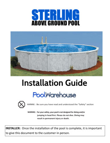
AQUASPORTS POOLS, LLC.OWNER’S MANUALMILANOABOVE GROUND RESIDENTIAL TYPE ONON-DIVING SWIMMING POOL52” HIGH, CORRUGATED WALLSROUND AND OVAL STEEL POOLS,INSTALLATION INSTRUCTIONSMEMBERTHESE PRODUCTS ARE MANUFACTURED INACCORDANCE WITH VOLUNTARY STANDARDSANSI/NSPI-4 DATED 1999 OR LATEST UPDATEAQUASPORTS POOLS, LLC. IS IN NO WAY AFFILIATED WITH ANY PROFESSIONALPOOL INSTALLER. THEREFORE, AQUASPORTS POOLS LLC. CANNOT ASSUMEANY RESPONSIBILITY FOR ERRORS IN INSTALLATION BY THE HOMEOWNER ORSAID PROFESSIONAL INSTALLER. IF YOU HAVE THE POOL, DECKING ANDFENCING INSTALLED BY OTHERS, PLEASE SUPERVISE TO BE SURE THEYCOMPLY WITH PROPER INSTRUCTION TECHNIQUES AS SHOWN.ISSUED MARCH 1, 1995TEXT UPDATED DECEMBER 1, 2005
SWIMMING POOL SAFETYINTRODUCTIONCongratulations on bringing swimming enjoyment to your family. Swimming is great fun for youngsters and grownupsalike. Having your own above ground pool is a satisfying delight, yet, there are a number of important above groundpool safety rules you must remember and enforce AT ALL TIMES. Failure to understand and enforce these safetyreminders can result in SERIOUS PERMANENT INJURIES, including, paralysis from a broken neck and damage tothe spinal cord or death from drowning or electrocution. You as the owner have the most important role in remindingusers of this above ground pool how to use it safely.DANGERSHALLOW WATERNEVER DIVE, SLIDE or JUMP into this ABOVE GROUND / ON GROUND POOL. ALWAYS supervise allusers, ESPECIALLY CHILDREN to prevent INJURY or DROWNING.PROVIDE MEANS OF INGRESS AND EGRESS FROM POOL BY MEANS OF LADDERS/STAIRCASES/STEPS ETCPERMANENT INJURY, PARALYSIS or DEATH can RESULT if you FAIL to OBEY this WARNING. ThisABOVE GROUND / ON GROUND POOL is designed for SWIMMING AND WADING ONLY! It is not DEEPENOUGH for SAFE DIVING, SLIDING or JUMPING.These Safety Reminders require pool users to EXERCISE COMMON SENSE. ALWAYS use COMMONSENSE in your use of this product in order to AVOID RISKS ASSOCIATED with electricity, and water to avoidserious injury resulting from JUMPS, DIVES, SLIDES, SLIPS, FALLS and ELECTRIC SHOCK.SAVE THESE INSTRUCTIONS!2
DANGERFAILURE to HEED THESE WARNINGS can RESULT in PERMANENT INJURY, PARALYSIS, or DEATH1. NEVER DIVE, SLIDE or JUMP into this ABOVE GROUND / ON GROUND SWIMMING POOL. It is tooshallow for safe jumping and diving.2. NEVER DIVE, SLIDE or JUMP from the LADDER, DECK, TOP LEDGE or ANYTHING ELSE.3. Always supervise small children to minimize the risk of drowning. Never allow children or adults to climb on theoutside structure of the pool. Do not put tables, chairs or other objects near the pool. Children may use these to enterthe pool and be injured or drown.4. Child Drowning Alert. US Consumer Product Safety Commission reports that drownings and near-drownings ofchildren, young adults and adults account for a substantial percentage of the risk of using this pool product.CHILDREN UNDER the AGE of 5 YEARS OLD are THE HIGH RISK. Please WATCH your CHILDREN!5. FOR YOUR ADDED SAFETY we urge you to install around the pool an additional four (4) foot tall (above groundlevel) fence, wall or enclosure that is made of durable material. ALL GATE AND ENTRIES must be self-closing andself-latching and equipped with hardware for permanent locking. ALL LATCHES MUST be installed fifty-four (54)inches above the ground surface and made inaccessible to toddlers from outside. If a building is part of the barrier, alldoors, windows and patio gates that could provide access to the pool MUST be SELF-CLOSING, SELFLATCHING, with PERMANENT LOCKS so that YOUR POOL CANNOT be ENTERED BY TODDLERS.Check all local and state building codes to insure your installation complies with all requirements.6. NEVER use your swimming pool AFTER DARK or when you cannot see all the parts of the pool. ALWAYSmaintain clean water in the pool. It is important that users must be able to see the shallow depth of the pool at all times.If you ignore this warning, you have the sole responsibility of providing adequate lighting and instructions so that allusers know and understand how to safely use this product. It is not safe to dive into shallow water because catastrophicpersonal injury or death could result. Because conditions and circumstances vary, you must consult with your electricalprofessional, such as a local electrical contractor or your power company, to provide adequate lighting for your intendeduse, and you must comply with all national and local electrical codes and safety requirements.7. NEVER use your swimming pool if you have been drinking alcoholic beverages or taking medications or drugs.Shock, unconsciousness, serious personal injury or drowning could result.8. NEVER attempt to contact or service electrical equipment, including your filter, when your body and/or the ground iswet. Electrocution or permanent personal injury due to high voltage (120V AC) could result.9. TO AVOID ELECTROCUTION HAZARD, never use an electrical power source for any electrical equipment oryour filter unless it is protected by a Class A (5 Milliampere Trip) Ground Fault Circuit Interrupter (GFCI) inaccordance with the National Electrical Code 680, latest revision 2002.10. For safe pool use the water must be clean, so that the bottom is visible at all times. The user must be able to see thatthe water is too shallow for jumping, sliding or diving, NO JUMPING---NO SLIDING--NO DIVING. FAILURE toHEED THESE WARNINGS can RESULT in PERMANENT INJURY, PARALYSIS, or DEATH.3
DANGER CONTINUED11. MOST SERIOUS PERMANENT INJURIES, PARALYSIS or DEATHS OCCUR when DIVES are made fromPOOL DECKS.12. BE SURE your pool and filter are installed as instructed in your OWNER’S MANUAL.13. NEVER allow horseplay in or around the pool.14. ALWAYS use Original Equipment Manufactured (OEM) parts for your replacement requirements.15. Make sure the filter is an Underwriters listed product for your own protection against electrical hazards.16. NEVER modify, remove or drill holes in the pool, deck, or ladder components unless instructed.17. NEVER INSTALL A SLIDE OR DIVING BOARD ON YOUR ABOVE GROUND / ON GROUNDSWIMMING POOL.18. If you COVER your POOL with a WINTER COVER, NEVER ALLOW ANYONE and ESPECIALLYSMALL CHILDREN to WALK or PLAY on the POOL COVER. SERIOUS INJURY AND DROWNINGCOULD RESULT!19. ALWAYS POST your “DO NOT JUMP---DO NOT SLIDE---DO NOT DIVE” signage in plain sight around oron your above ground / on ground swimming pool.20. PERIODICALLY check your pool and components for damage and be sure all screws are in place. Always replaceall damaged components and tighten all screws before you use the pool, deck or ladders.21. DO NOT CUT HOLES in your POOL WALL to INSTALL LIGHTS or ANYTHING ELSE UNLESS theHOLE LOCATIONS are FACTORY INSTALLED. FAILURE to OBEY this INSTRUCTION could CAUSESTRUCTURAL DAMAGE to the POOL WALL, VIOLENTLY RELEASING LARGE BODIES of WATER.WALL STRUCTURAL FAILURES may CAUSE SERIOUS INJURY, ELECTROCUTION, PROPERTYDAMAGE and VOID YOUR WARRANTY.22. IF YOUR “DO NOT JUMP---DO NOT SLIDE---DO NOT DIVE” SIGNAGE ARE MISSING, DAMAGED,OR NOT LEGIBLE, PLEASE WRITE OR CALL US FOR FREE REPLACEMENTS AT:AQUASPORTS POOLS LLCPO BOX 7283NORTH BRUNSWICK, NJ 08902Phone: 732-247-613423. Always have a light, strong, rigid pole (shepherds crook) not less than twelve feet (12’) long available at pool side incase of emergencies.24. ALWAYS post in a conspicuous place near your pool and telephone the following numbers:-Nearest Available Police, Fire or Rescue Unit-Nearest Available Physician-Nearest Available Ambulance Service-Nearest Available Hospital4
ABOVE GROUNDSWIMMING POOLINSTALLATIONINSTRUCTIONSINTRODUCTIONThese instructions have been prepared by themanufacturer to assist you in the installationof your new swimming pool. Read theseinstructions thoroughly before you begin thepool installation. Open the cartons andfamiliarize yourself with each part from itsdescription in the parts list. Then follow theinstallation procedure in the order given. Donot deviate from the instructions. Do not takeshort cuts. The warranty is not valid if theinstructions are not followed.IMPORTANTIf you are adding any additional added valuecomponents to your pool, such as fencing,patio decks, side decks, end decks, orcomplete walkarounds, it is important toreview those instructions before installing thepool. Pay particular attention to the priorattachment of fence/deck support bracketsto specific uprights and buttresses, beforeassembling these specific uprights andbuttresses to the bearing plates.SELECTION OF POOL SITEBefore proceeding with the installation,consider these items in choosing the locationof you pool. Look over your property for themost ideal location. A large area is best. Ifyou have no flat area large enough for thepool, then try to pick a spot where you wouldhave the least amount of digging to do. Donot install your pool with any of the pool walllocated in a major water drainage depressionor sewer drain field.B. The pool filter is electrically operated, soprovision must be made for an electric supply.C. It is important that the ground surface befirm and solid. The area must be free of glass,stones, roots, and sharp objects. Any stonesor roots flush or below the ground surfacemust be removed. The earth below the poolwill compress under the weight of the waterand will expose these items to the linercausing damage. Any grass under the poolwill rot and give off an unpleasant odor.D. Avoid installing your pool on ground thathas been recently treated with oil base weedkillers, chemicals, or heavily fertilized. Avoidareas growing nut grass or Bermuda grass.(These grasses can grow up through the poolliner.)E. Do not install the pool on asphalt, gravel,peat moss, wood, tar paper, or over any arearecently treated with chemicals.F. The pool should never be placed directlyunder overhead power lines for precautionarymeasures. In some communities this isagainst the law.G. Before you start digging into the ground tolevel the surfaces, it would be wise to checkwith your telephone, electric, and gas utilitiesfor the location of any underground lines orpipes.H. Trees and their occupants are not the bestof friends with swimming pools. Fallingleaves, branches and sap can be a constantproblem in keeping the pool water clean.(along with bird droppings and insects fallinginto the pool).These materials willnecessitate cleaning your filter unit moreoften. The further away from a tree the betterfor your pool.A. The area should be large enough to allowspace for lounging chairs, tables andaccessories as well as the pool ladder andfilter.5
IMPORTANTBefore beginning your pool installation, take afew minutes to consider the following points:1. Check easement requirement.2. Check wall clearances.3. Check decking clearance.4. Avoid overhanging eaves.5. Avoid overhead power lines.6. Avoid trees and leaves falling into thepool7. Avoid roots, underground piping andcables.8. No sudden slopes within 6 feet of pool.9. Keep sprinklers away from pool walls.10. Avoid sun reflection into residence.11. Allow 6 inches of undisturbed soilaround pool.12. Be able to view children near pool.13. Determine filter and pump location.14. Locate convenient electrical outlets forfilter and pump location.15. Check prevailing winds.16. Avoid windy days during installation.17. Do not install liner on any abrasive areasuch as concrete, asphalt, peat moss, tarpaper, gravel, wood, top of grass orrecently chemically treated soil.18. Do not install liner on nut grass orbermuda grass. See your dealer forspecial instructions.19. Rid pool area of burrowing pest andinsects such as gophers and termites.20. Have 2 or 3 helpers when installing pool.TOOLSThe following tools will be required forinstallation:Regular Screw Driver Measuring TapePhillips Screw Driver Smooth FileWrenchesLevelPeg or StakeHammerRakeStraight PlankShovelEmery ClothTamping ToolRoller (if available)Sharp knife/Razor BladeSilting screen (to remove 1/8” pebbles orlarger)MATERIALSThe following materials will be required forinstallation:12” X12” Patio Blocks, CordDuct or Masking Tape, Wood StakesELECTRICAL REQUIREMENTS;All Electrical Components installed in and /oradjacent to an aboveground/onground residentialswimming pool shall comply with the requirementsof Article 680 of the latest revision of the NationalElectrical Code 2002(NEC*) and any state orlocal code to apply the NEC’s interpretation ofthe electrical requirements .We refer you toANSI/NSPI-4 Dated 1999 Section 13.1.2WHICH STATES AS FOLLOWS:“The National Electrical Code 2002 definesPermanently Installed Swimming, Wading andTherapeutic pools as Pools that are constructed in theground or partially in the ground, and all otherscapable of holding water in a depth greater than fortytwo inches (42”), and all pools installed inside abuilding, regardless of water depth, whether or notserved by electrical circuits of any nature.If you elect to have the pool partially installed inthe ground, there are several areas of concernalerting you to potential significant problem areasthat must be addressed.A. The pool installed partially in the ground,appears to be an Inground Pool, and thereforecreates an invitation for an individual orindividuals, to dive into the pool, regardless of thesafety labels affixed to the Top Rails, Wall andLiner. Fill the pool with water prior to backfilling.B. Placing the pool structures partially in theground accelerates corrosion of the metal parts.Preventative measures must be taken to retardthis accelerated deterioration. Installer surfacepreparation and treatment must be administeredto all structural parts, prior to being placedpartially in the ground. This reduces theaccelerated deterioration. It does not eliminate theproblem.6
FILTERSFiltration is a mechanical means for removingsmall particles of dirt and sediment from thepool water. Your pool filter and otheraccessories are operated by electricity. Youmust have all outside electrical outletsinstalled by a qualified electrician inaccordance with National Electric Code 680.Filter, hand skimmers, and vacuum cleanersare available at your pool dealer.WATER CHEMICALSAll pools, whether filtered or not, requirepurifying or sanitizing of the water. Themost common pool chemical used for thispurpose is chlorine. It is available in variouscontainers as a powder (granular), tablets andliquid. Follow the directions on the container.Always dissolve the tablets or powder beforeputting it into the pool.Proper dailychlorination of pool water, even when thepool is not used, will insure a sparkling, algaefree, healthy pool. Familiarize yourself withcommon vocabulary terms in Advisory X.CAUTIONWe cannot over emphasize this phase of yourpool installation. While some tolerance inslope is allowed, (not more than 2” fromend to end or side to side) the ideal conditionwould be exact levelness and you should useextreme care to achieve that result. High andlow spots may not affect the overall shape ofthe site, but they should be eliminatedespecially where the pool wall will stand.Irregularities could make walking in the pooldifficult.DISASSEMBLE AND STORAGEDo not remove the water from your pool. Ithas been designed to remain installed andfilled with water all year round.Werecommend the use of a pool cover to protectit and keep it clean when not in use. If youdecide to disassemble the pool, drain andreverse the installation procedure.Clean and dry the pool liner before packingPut all hardware in a containerRecoil and tie the pool wallClean and dry all frame partsUPRIGHTS - STEELC. Attach Steel Upright, No. 2 to roundbottom joiner, No. 20B (Fig. 4) and fastensecurely with four (4) 10x5/8” washer headscrews No. 25B. Repeat this process for allinstalled Uprights, No. 2.). Be sure the holesfor fence bracket attachment are not at thebottom of the pool upright.ROUND POOL ASSEMBLYPOOL LOCATIONA. Locate the center of the pool. Drive thepeg into the ground. Cut pieces of string orcord equal to the radius (1/2 diameter) of yourpool. Mark off the circle (Fig. 1). Removeall the grass and sod inside the marked offarea and level ground (Fig. 2A). Use a strongplank to level (Fig. 2B). Remove all sharpstones and twigs. The entire pool area mustbe absolutely level.CURVED WALL RAILSB. Lay out lowered Curved Wall Rails, No.13, and Round Bottom Joiner, No. 20B (Fig.3), around circle. PLACE PATIO BLOCKSUNDER EACH ROUND BOTTOMJOINER.THISWILLPREVENTSINKING OR SETTLING OF THEUPRIGHT. Slide Curved Wall Rails, No.13, into Round Bottom Joiners, No. 20B,(Fig. 3).UPRIGHTS - RESINAttach Resin Upright, No. 2 to roundbottom joiner, No. 20B (Fig. 4) and fastensecurely with two (2) 10x5/8” washer headscrews No. 25B. on each side of the uprightand one (1) 10X3/4 screw No. 57 in the centerof the upright. Repeat this process for allinstalled Uprights, No. 2. ). Be sure theholes for fence bracket attachment are notat the bottom of the pool upright.7
WALL CARTOND. Place the Wall Carton and Pool Linercarton inside pool area (Fig. 2C)WALL SKIMMERE. If you are installing a through the wallskimmer on your pool, you must decide whereyou will locate your filter system since it isconnected to the skimmer. The skimmershould be placed in the direction of theprevailing wind so that it can effectivelyremove wind blown leaves and dust from thewater surface.WALL -- GET HELPF. The Wall is heavy, get help. Carefully andslowly unspool the Pool Wall. Start insertingthe Pool Wall into the Curved Wall Rail, No.13 (Fig. 6). Continue inserting the Pool Wallinto the curved rail all the way around thepool. If the end wall holes do not match,adjust the Curved Wall Rails and Joiners untilthe proper fit is attained. Close the Wall byinserting 1/4-20x5/8” screws and nuts, No.24A & 24B with the screw head toward theinside of the pool and the nuts on the outsideof the Wall. (Fig. 6 & 7) Remove any burrsraised on the screw heads and cover the screwheads and sharp edges with masking tape orduct tape.WALL CONNECTIONG. It is absolutely necessary and essential thatWall, No. 1, overlaps as shown in Fig 6 & 7.Due to the tremendous water pressure exertedon the pool wall, it is important that all (32)nuts must be securely tightened on all bolts.Do not leave any open holes.IMPORTANTWhen connecting the pool side wall, makesure that one Metal bar faces inside towardthe Liner and the other Metal Bar facesoutside the Pool Wall (Fig. 6 & 7). Seecorresponding instructional affixed walllabel.VINYL LINER INTRODUCTIONGeneral Procedures, Cautions, andMaintenance InformationPRIOR TO LINER INSTALLATION ITIS RECOMMENDED THAT YOU READTHE GENERAL PROCEDURES ANDINFORMATION1. The function of the pool liner is to act as awater envelope keeping the water in the pool.It is not a structural component, nor is itdesigned to support the weight of the water.The water pressure is held by the poolstructure, not the liner. The liner must beinstalled properly with all liner surfacestouching the ground, cove, and pool wall andthe liner not supporting the weight of thewater.2. The pool liner must be installed onsmooth, level ground.3. A COVE, approximately 6” high andforming a diagonal against the inner pool wallmust be constructed, using suitable siftedearth or dead sand (do not use peat moss)around the entire inner circumference of thepool where the pool comes in contact with theground. This COVE is necessary to providesupport at the critical point where the sidewall of the liner is joined to the liner bottom.It is essential that the seam joining the liner’sside wall and bottom rest on this cove. If itdoes not, the seam will tear from the weightof the water.4. Pool sizes vary slightly and above groundliners are generally cut slightly oversize toavoid damage by shrinkage. The appearanceof slight wrinkles during installation is notuncommon. DO NOT attempt to eliminatethese wrinkles by pulling the excess materialover the side of the pool, since this may causedamage to the liner. DO NOT pull or dragyour liner.5. Your pool and liner should be full of waterat all times. Emptying the pool may result instructural damage to the pool as well asshrinkage of the liner.8
POOL LINER WORKMANSHIPINSTALLATION INSTRUCTIONS1. Be sure the ground is level and properlyprepared.2. Build the cove around the entire innercircumference of the pool wall.3. Place the liner in the center of the pool andunfold. Be sure that the liner is centeredinside the pool.COVEH. Do not use any material that willcompress under pressure. The cove is animportant part of the pool installation. Usingneutral alkalinity sifted earth, or fine sandwithout pebbles, build a 2” base over theentire pool area to protect the liner. DO NOTUSE ANY SUBSTANCE WITH HIGHALKALINE OR ACID CONTENT,ESPECIALLY PEAT MOSS, AS IT WILLCORRODE METAL PARTS! Next, usingthe sifted earth or fine sand, build a pool cove6” high inside the metal wall along the entirecircumference. This will prevent the linerfrom creeping under the wall, and it will alsoprotect the liner from any metal edges of thepool framework. THIS STEP IS NOTOPTIONAL- IT MUST BE DONE! Sinceearth containing chemicals can causediscoloration or corrosion, it is suggested thatyou place polyethylene plastic sheeting underthe cove around the perimeter of the wall, sono earth comes in contact with the metal.Since the presence of such chemicals isbeyond the control of the manufacturer, suchdamage is not covered by the warranty.After the cove and the base are in place, rakeand tamp the entire pool area. Make sure thatno sand is allowed to remain on the wallabove the cove. This could cause pinholes inyour liner. (Fig. 8 & 9).CAUTION--LINER INSTALLATIONThere are two (2) types of liners used forabove ground/onground pools: The First Typeis called an Overlap Liner. This Liner isdraped over the Pool Wall and held in placewith the use of plastic coaming.The Second Type is called a Beaded or HungLiner. This Liner requires a Beaded LinerTrack, which is placed onto the corrugatedpool wall and the beaded portion of the lineris placed or snapped into the retainer portionof the beaded liner track.Before installing the Liner, remove anyburrs on the screw heads, or sharp edges andbe sure to Tape and Cover all Exposed MetalEdges, Sharp Corners, and knockout plugs inthe Skimmer, Wall Panel, Return Outlet.Place tape over the joints on the beadedreceiver with masking tape or duct tape on theinside of the pool as well as the Metal Barwhere the Wall is connected to protect theLiner from damage. (Fig. 6 & 7). Failure totape these areas may result in sharp edges,eventually cutting through the Liner, causingthe Liner to tear. It will also help to preventpool waters from getting between the Linerand the pool wall.4. FOR OVERLAP LINERS:Drape the Liner Side Wall over the top of thepool wall REMEMBER! The seam joiningthe Liner Side Wall to the bottom must rest onthe Cove! There should be approximately 4”6” overhang of the Liner over the pool wall.5. FOR BEADED LINERS:Drape the Liner inside the pool wall. Snap thebead of the Liner into the beaded linerreceptor at the top of the pool wall.6. Smooth out wrinkles by pushing themtoward the pool wall with a soft broom. DONOT eliminate wrinkles by pulling excessliner material over the side of the wall orpoking at the wrinkles with a stick or otherobject. This will damage the Liner.LINER---GET HELPI. Open the carton, No. 10, carefully. Do notuse a knife or other sharp object. YourVinyl Pool Liner has been carefully inspectedat the factory, but you should check thesurface and the seams of the Liner for defects,holes, cuts, tears, etc. before walking orstanding on the Pool Liner. Do not try to9
install the Pool Liner by yourself, as youmight accidentally tear or puncture the liner.It is heavy and to install it correctly you willneed help. Ask a few of your friends to help.Spread the Liner on the bottom of the pooland center the bottom seam on the cove. Fig.8 & 10.OVERLAP LINERSLift the sides of the Liner and carefully drapeover the top edge of the pool side wall aroundthe entire pool. The Overlap Liner shouldoverlap the Pool Wall approximately 6” fromthe top, Fig. 11. Secure the Liner, No. 10, totop of the pool side wall, No. 1, with strips ofPlastic Coping, No. 9, placed end to end.Continue around the pool. Before going on tothe next step, check to be sure that the bottomseam is positioned on the cove. If not,remove the Plastic Coping, No 9 and adjustthe Liner, No 10 Fig 8 & 11INSTALL BEADED RECEPTOR TRACKFOR BEADED LINERSThe Beaded Liner should be FITTED orSNAPPED into the Beaded Liner Track, No.13F, continuing around the entire tracksections. Next, SNAP or SLIDE a 6 ” pieceof wall rail, No. 13R over the joints of theBeaded Liner Receptor, No. 13F. Check to besure that the Bottom Seam of the LINER No.10, is positioned on the curve of the sandcove. See Fig. 9.INSTALL TOP CURVED WALL RAILSFOR OVERLAP LINERS ONLYJ. Around the entire top of the pool wall,install the Curved Wall Rails, No. 13, over thePlastic Coping. See Fig. 6 These CurvedWall Rails, No. 13 on the top, will be aboveand in-line to the previously installed curvedwall rails, No. 13 at the bottom. Fig. 3 & 4INSERT TOP JOINERSK. See Fig. 9. After installing either CurvedWall Rails, No. 13 over the Plastic Coping orBeaded Track, No. 9 insert the Round TopJoiners, No. 20A, over the Curved Wall Railsor Beaded Track, on the top which will beabove and in-line to the previously installedCurved Wall Rails, No. 13 at the bottom.Fig. 3 & 4.TOP RAILSL. Place the beveled Top Rails, No. 3 on topof the Round Top Joiners, No. 20A. Fastentogether with four (4) 10x5/8” screws, No.25B. See Fig. 12. Cover all exposed sharp cutmitres with masking or duct tape.TOP CAP SETSM. Place the Inside Cap, No. 12A and theOutside Cap, No. 12B, over and covering allthe exposed seams where the Top Rails, No. 3meet at the Round Top Joiners, No. 20A.Secure the Caps, No. 12A & 12B, to each TopJoiner, No. 20 with one 14x1” SS Screw, No.26 for STEEL toprails and for RESINtoprails use 14x1-1/2 SS Screw No 26A, Fig.13. For the Milano, attach the Outside Cap,No. 12B, to the Upright by drilling a 1/8” holein the Upright and secure with one 14x1” SSScrew, No. 26. See Fig 14OVAL POOL ASSEMBLYPOOL LOCATIONLocate the center of the pool. Drive the peginto the ground. Cut pieces of string or cordequal to the length of the straight side of yourpool. Cut pieces of string or cord equal to theradius (1/2 diameter) of your pool. Mark offthe circle (TABLE 1, Fig. 15). Remove allthe grass and sod inside the marked off areaand level ground (Fig. 2A). Use a strongplank to level (Fig. 2B). Remove all sharpstones and twigs. The entire pool area mustbe absolutely level.CAUTIONWe cannot over emphasize this phase of yourpool installation. While some tolerance inslope is allowed, (not more than 2” from endto end or side to side) the ideal conditionwould be exact levelness and you should useextreme care to achieve that result. High andlow spots may not affect the overall shape ofthe site, but they should be eliminatedespecially where the pool wall will stand.Irregularities could make walking in the pooldifficult.10
BOTTOM STRAP ASSEMBLYA. Lay out Bottom Strap, No. 17 as shown.(Fig 19, 19A, 19B, 19C, 19D & 19E)1. Attach Universal Aluminum Joiner, No. 21and Bottom Square Channel to Bottom Strapat indicated positions using 4 (four) 1/420x5/8 screws and nuts, No 24. (Fig. 21)ATTACH STRAP ANGLE2. Attach Strap Angle, No. 22 to BottomStrap, No. 17, using four (4) 1/4-20x5/8”screws and washer nuts, No. 24 (Fig. 22 &23). Connect each set of Bottom Straps, No.17 by overlapping each strap to correspondingholes. Secure with 1/4-20x5/8” screws andwasher nuts, No. 24. Make sure that allWasher Nuts are on the Bottom Side of thestrap. (Fig.19E & 21)Place your Bottom Straps parallel to eachother and 36” apart on 2x8 planks (Fig. 17,19D, & 25). PLACE PATIO BLOCKSUNDER EACH UNIVERSAL BOTTOMJOINER.THISWILLPREVENTSINKING OR SETTLING OF THEBUTTRESS UPRIGHT ASSEMBLY.Take Straight Wall Rails, No. 4 and sleevethem through the Universal Joiners, No. 21.(Fig 24 & 25)BUTTRESS/BRACE ASSEMBLYB. Buttress Assembly (Fig 21, 22, 24 & 25)1.Buttress Assembly is pre-assembledattaching a Buttress Bracket, No. 14, withsharp corners facing down using two (2) 3/816x1” screws and nuts, No. 23. Selecting theend of the Buttress Brace, No. 16, that hasside holes, Fig. 26, slide the Buttress Support,No. 16, over the Buttress Support Bracket,No. 14. Insert two (2) 1/4-20x5/8” screws,No. 24A & 24B on the inside of the ButtressSupport, No. 16. Fig. 26.2. Take the Buttress Assembly, Fig. 26, andslide into Buttress Support Angle, No. 22.Attach the Buttress Support, No. 16, to theStrap angle, No. 22, using two (2) 10x5/8”screws. (Fig. 27)3. Attach the Buttress Upright, No. 19, bysliding it over the Bottom Square Channel,No. 15 so that the Channel is inside theButtress Upright, No. 19, Fig. 28. Securewith four (4) 1/4-20x5/8” screws and washernuts, No. 24 and two (2) 10x5/8” self tappingscrews, No. 25B, Fig 28 & 29.BOTTOM CURVED RAILSC. For the round end of the pool, take theCurved Wall Rail, No. 13 and insert it halfway into the Universal Joiner, No. 21, Fig. 3.Next, take a Bottom Round Joiner, No. 20Band slide it half way over the other end of thejust installed Curved Wall Rail, No. 13.PLACE PATIO BLOCKS UNDER EACHROUND BOTTOM JOINER. THIS WILLPREVENT SINKING OR SETTLING OFTHE UPRIGHT. Continue connecting theCurved Wall Rails, No. 13 with RoundBottom Joiners, No. 20 until you reach theBottom Strap, No. 17 and connect into theUniversal Aluminum Joiner, No. 21 on theopposite side. Repeat this procedure for theother round end. After all Curved Wall Rails,No. 13 are in place, check to be certain thatend circles are round and centered on thecenter line of the pool. This is important. Ifthe round ends are off center, you mayexperience difficulty installing the pool TopRails. Fig. 30.SIFTED EARTHD. Cover all Bottom Strap Assemblies, Fig.19E with a minimum 1” of sifted earth ord
above ground / on ground pool. always supervise all users, especially children to prevent injury or drowning. provide means of ingress and egress from pool by means of ladders/staircases/ steps etc . permanent injury, paralysis. or . death. can . result. if you . failto obey. this . warning. this . above ground / on ground pool. is designed for .