Transcription
On Multiphase Flow Models inANSYS CFD SoftwareMaster’s Thesis in Applied MechanicsELIN STENMARKDepartment of Applied MechanicsDivision of Fluid DynamicsCHALMERS UNIVERSITY OF TECHNOLOGYGöteborg, Sweden 2013Master’s thesis 2013:11
MASTER’S THESIS IN APPLIED MECHANICSOn Multiphase Flow Models in ANSYS CFD SoftwareELIN STENMARKDepartment of Applied MechanicsDivision of Fluid DynamicsCHALMERS UNIVERSITY OF TECHNOLOGYGöteborg, Sweden 2013
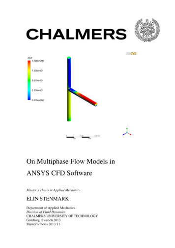
On Multiphase Flow Models in ANSYS CFD SoftwareELIN STENMARK ELIN STENMARK, 2013Master’s Thesis 11ISSN 1652-8557Department of Applied MechanicsDivision of Fluid DynamicsChalmers University of TechnologySE-412 96 GöteborgSwedenTelephone: 46 (0)31-772 1000Cover:Volume fraction of air in vertical T-junction with horizontal branch.Chalmers Reproservice / Department of Applied MechanicsGöteborg, Sweden 2013
On Multiphase Flow Models in ANSYS CFD SoftwareMaster’s Thesis in Applied MechanicsELIN STENMARKDepartment of Applied MechanicsDivision of Fluid DynamicsChalmers University of TechnologyABSTRACTMultiphase flow is a common phenomenon in many industrial processes, amongstthem the oil and gas industry. Due to the complexity of multiphase flow, developmentof reliable analysis tool is difficult. Computational fluid dynamics (CFD) has been anestablished tool for flow analysis in the field of single phase flow for more than 20years but has only started to become established in the multiphase field as well. To beable to use CFD in a meaningful way it is important to investigate, understand andvalidate the many models offered in commercial codes. The purpose of this thesis is tocompare multiphase models available in the ANSYS software Fluent and CFX andperform simulations using the different models. The simulations were based on anexperimental study concerning air-water mixtures in a vertical T-junction withhorizontal branch. When a gas-liquid mixture flows into a branching pipe junctionphase redistribution will occur and a higher proportion of gas will enter the sidebranch. The aim of the simulations was to find models/settings that accurately predictthe phase redistribution phenomenon and investigate the effect of changing simulationparameters. This was done by systematically changing parameters and validating theresults against the experimental data. Based on the simulations, it was evident that theEuler-Euler modelling approach was best suited for predicting the phase redistributionphenomenon in the T-junction. The choice of dispersed phase diameter was found tohave the largest effect on the results. Generally, the predicted average volume fractionin each arm was in quite good consistency with experimental data while the predictedvelocities were in low agreement. However, adding models to account forpolydispersed flow increased the agreement also for the velocity.Key words: Multiphase, Computational fluidredistribution, Euler-Euler, VOFdynamics,T-junction,PhaseI
II
RODUCTION11.1Objective21.2Delimitations21.3Thesis outline2THEORY2.1Multiphase flow theory2.1.1Modelling approaches2.2Computational fluid dynamics2.2.1The finite volume method2.2.2Coupled and segregated solvers3VISOFTWARE446111112143.1ICEM CFD143.2Fluent143.3CFX154EXPERIMENTAL STUDY175METHOD1865.1Geometry and Mesh185.2Simulation settings215.3Boundary conditions255.4Convergence criteria265.5Evaluation criteria27RESULTS AND DISCUSSION286.1Phase separation phenomenon286.2Prediction of global parameters326.3Prediction of local distributions356.4Comparison between Fluent and CFX41CHALMERS, Applied Mechanics, Master’s Thesis 2013:11III
6.5Effect of changing simulation parameters6.5.1Dispersed phase diameter6.5.2Phase formulation6.5.3Turbulence model6.5.4Discretisation scheme for volume fraction equation6.5.5Drag law6.5.6Turbulent dispersion6.5.7Mesh size6.5.8Time formulation4242434445454647516.6Investigation of models for polydispersed flow546.7Convergence issues and tips for convergence556.8Error Sources567CONCLUSIONS7.18IV58Future work58REFERENCES60CHALMERS, Applied Mechanics, Master’s Thesis 2013:11
PrefaceIn this thesis, the use of multiphase flow models in ANSYS CFD software has beeninvestigated. The work has been carried out from January 2013 to June 2013 at AkerSolutions in Gothenburg in collaboration with the Division of Fluid Dynamics at theDepartment of Applied Mechanics, Chalmers, Sweden.I am very grateful to Aker Solutions for giving me the possibility to do this work.Many thanks go out to my supervisor at Aker Solutions, Ph.D. Jonas Bredberg, for allthe support and the many ideas. Thanks to everybody at Aker Solutions, especially theEST group, for making me feel welcome. I would like to express my greatestappreciation to Professor Lars Davidson at the Division of Fluid Dynamics for beingwilling to take on the role as examiner for this thesis and for helping me with findingthis interesting project. Great thanks also go out to Docent Srdjan Sasic at the divisionof Fluid Dynamics for helpful ideas and comments.Last but not least, thank you Sami Säkkinen for always supporting me and for beingmy best friend.CHALMERS, Applied Mechanics, Master’s Thesis 2013:11V
NotationsGreek symbols Volume fraction DensityτViscous stress tensorRoman symbolsBBBirth due to breakageBCBirth due to coalescenceDBDeath due to breakageDCDeath due to coalescenceGGrowth termgGravitynNumber density of particlespInstantaneous pressurePMean pressure shared between the phasesSSource termuInstantaneous velocityUMean velocityVVolumey Dimensionless distance from the wallAbbreviationsCFDComputational Fluid DynamicsDNSDirect Numerical SimulationsFMVFinite Volume MethodGVFGas Volume FractionHRICHigh Resolution Interface CapturingIACInterfacial Area ConcentrationMUSIGMultiple Size GroupPBMPopulation Balance ModelQMOMQuadrature Method of MomentsVICHALMERS, Applied Mechanics, Master’s Thesis 2013:11
SIMPLESemi-Implicit Method for Pressure-Linked EquationsSSTShear Stress TransportSSMStandard Method of MomentsVOFVolume of FluidSubscriptsBBreakageCCoalescencefFluid phasekk:th phasemMixed propertiesmassMasspParticle phaseCHALMERS, Applied Mechanics, Master’s Thesis 2013:11VII
1IntroductionMultiphase flow is common in many industrial processes, amongst them the oil andgas industry. Enormous quantities of oil and gas are consumed on a daily basis (CIA2013) and even a slight enhancement in extraction efficiency will have a significantinfluence on revenues for companies in the oil and gas industry. Hence, findingreliable analysis tools for understanding and optimisation of multiphase flows is apriority for these companies. One of these companies is Aker Solutions, wherecomputational fluid dynamics (CFD) is used in the development of subsea equipment.CFD was developed during the second half of the 20th century and became anestablished analysis tool for single-phase flow calculations during the 90ies with theappearance of commercial CFD software such as ANSYS Fluent and ANSYS CFX.The use of CFD in the area of multiphase flow is not as established. However, withthe development of computer resources, making more complex analyses possible,along with the incorporation of multiphase flow models in commercial codes such asthose previously mentioned, CFD is now gaining more importance also in this field(Crowe et. al 2012).Several error sources exist for numerical simulations. Numerical approximation errorswill always occur but another error source, which often is difficult to detect, is usageerror. Unintended application of models, badly chosen parameters or wrongfullyapplied boundary conditions can lead to unphysical and inaccurate results. With theextended use of CFD simulations in engineering work it is of high importance toinvestigate the accuracy of commercial codes as well as understanding the choice ofmodels. This is particularly important for multiphase flow where the complexity ofboth physical laws and numerical treatment makes the development of general modelsdifficult (Wachem and Almstedt 2003).Not much published work has been done on comparing commercial CFD codes andas models and codes may be intended and developed for a certain multiphase area,what is accurate and applicable for one business area might be unsuitable to use foranother area. Therefore, there is a need to examine and compare the models availableto create a knowledge base for multiphase flow simulations using commercialsoftware in the oil and gas industry.CHALMERS, Applied Mechanics, Master’s Thesis 2013:111
1.1ObjectiveThe objective of this thesis is to, through numerical simulations and validation againstexperimental data, build up a knowledge base that can be used for defining multiphaseCFD procedures at Aker Solutions. Multiphase models available in ANSYS CFDsoftware will be investigated to find their usefulness for different flow cases as well astheir limitations. Simulations will be performed with systematic parameterisation toinvestigate the effect of changing models and parameters. The simulations will bebased on an experimental study to enable validation of the results. The findings of themodel survey and simulations will result in general recommendations for multiphaseCFD simulations including guidance on the effect of choice of models, settingsetcetera.1.2DelimitationsOnly the multiphase models available in the ANSYS CFD codes CFX and Fluent willbe investigated. The reason for this delimitation is that this is the software presentlyused for flow simulations at Aker Solutions. Restrictions are also made in the numberof models and settings that can be tested as it is not feasible to investigate all themodels that are available in the ANSYS CFD software during the 20 weeks in whichthis project is to be carried out.1.3Thesis outlineThis thesis is organised in eight chapters. After the introduction, Chapter 2 containsbasic theory about fluid flow in general, multiphase flow and the most commonmodelling approaches for multiphase flow. In addition, some basic theory about CFDis given.Chapter 3 presents the software used and in Chapter 4 a short review of theexperiment used as benchmark for the simulations is given.2CHALMERS, Applied Mechanics, Master’s Thesis 2013:11
In Chapter 5 the methodology is described. Geometry, mesh, simulation settings andboundary conditions are presented and convergence and evaluation criteria arediscussed.The results are presented and discussed in Chapter 6 and in Chapter 7 conclusionsfrom the study are drawn. Finally, the references are stated in Chapter 8.CHALMERS, Applied Mechanics, Master’s Thesis 2013:113
2TheoryEquations are used to mathematically describe the physics of fluid flow. Thecontinuity equation and the momentum equation, also known as the Navier-Stokesequation, are needed to describe the state of any type of flow and are generally solvedfor all flows in CFD modelling, see equation 2.1 and 2.2, respectively (ANSYS CFXSolver Theory Guide 2011). Additional equations, such as for example the energyequation and/or turbulence equations, might be needed to properly describe a flowdepending on the nature of the particular flow. ( u) 0 t(2.1) u ( uu) p τ g t(2.2)Here ρ is density, u is instantaneous velocity, p is pressure, τ is the viscous stresstensor and g is the gravity vector.Solving the governing equations without any modelling is called direct numericalsimulations (DNS). Running DNS-simulations is very time consuming. In practice, allflows are turbulent and turbulent flow exhibits time scales of such significantlydifferent magnitudes that the mesh resolution needs to be so fine that the calculationtimes become unfeasible. Therefore, modelling is often employed to account for theturbulent effects and the topic of turbulence modelling has been the main focus ofsingle-phase CFD research for the last couple of years (Crowe et. al 2012).Multiphase flow requires even further modelling due to the complex behaviour ofinteraction between the phases. Even when doing DNS-simulations for multiphaseflow, modelling is needed. Section 2.1 gives the basics of multiphase flow and inSection 2.2 some of the fundamental concepts of CFD are given.2.1Multiphase flow theoryMultiphase flow is flow with simultaneous presence of different phases, where phaserefers to solid, liquid or vapour state of matter. There are four main categories ofmultiphase flows; gas-liquid, gas-solid, liquid-solid and three-phase flows. Furthercharacterisation is commonly done according to the visual appearance of the flow as4CHALMERS, Applied Mechanics, Master’s Thesis 2013:11
separated, mixed or dispersed flow. These are called flow patterns or flow regimesand the categorisation of a multiphase flow in a certain flow regime is comparable tothe importance of knowing if a flow is laminar or turbulent in single-phase flowanalysis (Thome 2004).A flow pattern describes the geometrical distribution of the phases and the flowpattern greatly affects phase distribution, velocity distribution and etcetera for acertain flow situation. A number of flow regimes exist and the possible flow patternsdiffer depending on the geometry of the flow domain. For some simple shapes, forexample horizontal and vertical pipes, the flow patterns that occur for different phasevelocities etcetera have been summarised in a so called flow map. Figure 2.1visualises the flow configuration for some possible flow regimes and Figure 2.2shows an example of a flow maps for horizontal pipe flow.Figure 2.1 Example of typical flow patterns for flow in horizontal pipesCHALMERS, Applied Mechanics, Master’s Thesis 2013:115
Figure 2.2 Example of flow map for two phase flow in horizontal pipes. Based on figure by Brill andArlrachakaran (1992).The two extremes on a flow map is dispersed flow and separated flow. In separatedflow there is a distinct boundary between the phases. Examples of separated flow isstratified f
computational fluid dynamics (CFD) is used in the development of subsea equipment. CFD was developed during the second half of the 20th century and became an established analysis tool for single-phase flow calculations during the 90ies with the appearance of commercial CFD software such as ANSYS Fluent and ANSYS CFX.
