Transcription
Computational Domain Selection forCFD Simulation
Scope of the this PresentationThe guidelines are very generic in nature and has been explained with examples.However, the users may need to check their problem set-up with the intendedoperating conditions, testing environment to establish a realistic simulation setup.1.Why selection of computational domain is important?2.Basic principles of selection (size and envelop) of the computational domain3.Geometry simplification recommendation for computational domain4.Examples
Domain Selection: A PreludeThe underlying assumptions and mathematical constraints involved with Computational FluidDynamics has made it an ART rather than a science or industrial engineering application. Ascientifically correct simulation not only demand the correct understanding of underlyingphysics of the problem at hand (which is true in most of the engineering applications), a keensense of testing, measurement and instrumentation is equally important. For example, if a CFDengineer (for purist “CFD analyst”) is planning to generate the performance characteristics of aVenturi-meter or an Orifice-meter, he must give attention to the test set-up historically usedfor this purpose. It will involve asking questions like “What is the length of pipe upstream theactual measurement section?”, “Where is the pressure measured downstream the Venturi?”, Isthe pressure measured at only one location or at multiple angular position at a given cross-section? If yes, why?”, so on and so forth.In the following section, we will see how answer to these questions help (rather lead) us todecide the computational domain scientifically correct.
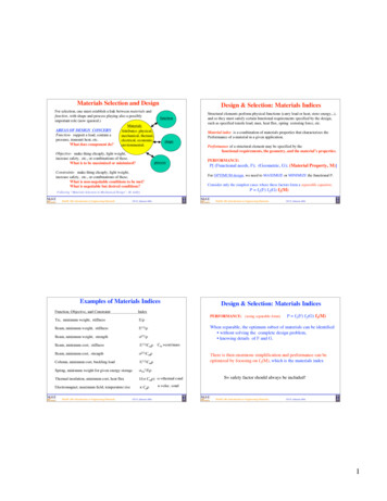
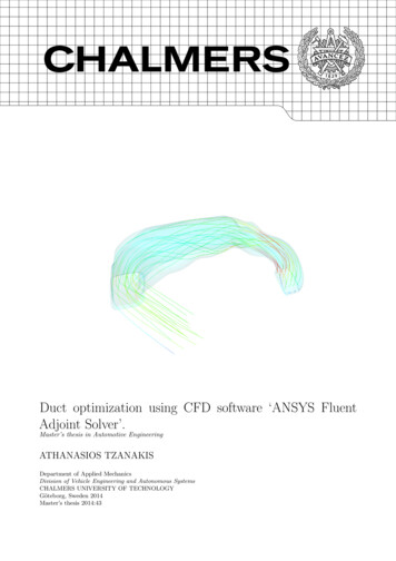
Domain Selection - BasicsBasic:Any CFD simulation involves 3D region or its simplified 2D counterpart) where fluid issupposed to occupy the space and flow. Hence, if one says that he is simulating flow through aU-bend, it is always assumed that the complete space inside the tube is filled with fluid underconsideration.Selection of computational geometry is not only dependent on the actual shape and size of theproduct. At the same time it must address the mathematical constraints under which a CFDsoftware solves the governing Differential Equations. The applicability of “Fully Developed” and“Developing” flow should be carefully thought of while deciding the computational domain. Letsus start with some examples before going into other details. In example below, for Outlet-1,clearly CFD will never produceDInlet X2DOutlet1(4 6)xDOutlet2
Domain Selections: Exemplifiedcorrect result even though the pipe length downstream the orifice-meter or control valve isvery short in actual application. Hence, to get a fairly accurate performance characteristics ofan orifice-meter or a Control Valve, it is vital to have a prior understanding of the highlyturbulent zone & length formed downstream such narrow passages. It must be emphasized thatthis requirement of knowledge should come from your basic understandings of Fluid Mechanicsand not from theory behind CFD. Questions such as the following was encountered in a forum, “Ihave written a CFD program to calculate laminar flows. Can someone provide me a benchmarkdata to validate my code?” I wonder who is the actual author of the code being refereed by themember! It is ironic to develop a CFD code development expertise without having the knowledgeof Hagen-Poiseuille flow equations.Symmetry: Domain simplification is a very common approach and if used judiciously, results inaccurate results faster with lesser computational resources. However, the inherent nature oflack-of-symmetry found in most industrial flow problems warns us to use this approach with apinch of salt.
Domain Selections: ExemplifiedExample-1: The much read and common flow configuration, flow over a cylinder (“Bluff Body”) isnot symmetrical at Reynolds Number typically encountered in industrial applications.Example-2: Flow with sudden expansion tend to be asymmetric even though geometry issymmetrical.
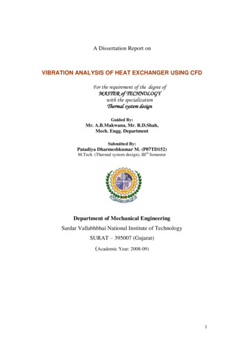
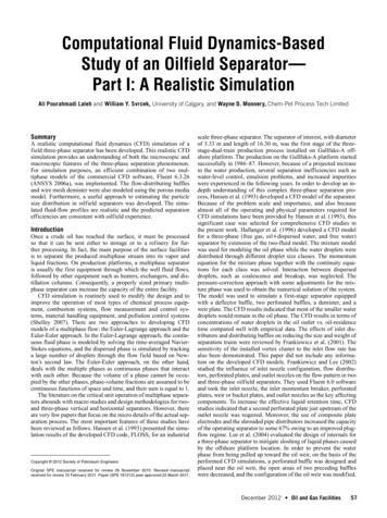
Domain Selections: Translation SymmetryExample-3: In the figure below, the flow domain proposed by dashed lines is incorrect sincethe flow in the wake region (region behind any “bluff body”, here the cubical step) is far frombeing symmetrical or periodic.InletOutletHeat Flux
Domain Selection: Tips and TricksC1C2Tips & Tricks-1: The above picture demonstrates flow over a extended surface also calledHeat Sinks and an integral part of CPUs. Assuming that the end effects are negligible and thereis no conduction losses in transverse direction (LH Fin RH Fin), there are two possiblescenario to select a domain incorporating “SYMMETRY”. Given the fact that the fin thicknesscannot be neglected as compared to gap between two consecutive fins, which configurationwould you choose and why?Answer: C1, Why?
Domain Selection: Automotive External AerodynamicsTips & Tricks-2: Domain length downstream the car (shown as “5 20 L”) can only be guessed byan expert aero-dynamist or by trial & error. These lengths have been selected based on typicalwind-tunnel used in industry. If you are simulating aerodynamics for a racing car, this size ofdomain may not suffice.2L5 20 LL2L2L2L
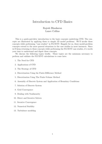
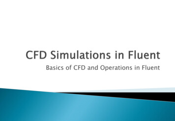
Computational Domain: Buoyancy Driven Flow over a Vertical Heated PlateTips & Tricks-3: The dimension ‘w’ should be large enough to affect the Boundary Layer growthon the vertical wall.OutletbLwIsothermalPlate at 100 CaInletFarfield at25 Cw/L 0.5b/L 0.1a/L 0.1
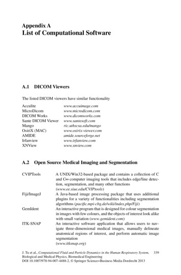
Computational Domain Selection: A Prior Insight in Flow Field is Equally ImportantTips & Tricks-4: Systematic experiments on 2D flows with pressure drop and pressure rise inconvergence and divergent channel with flat walls have been carried out by F. Doench, J. Nikuradse,H. Hochschild and J. Polzin. The included angle of the channels ranged over -16 , -8 , -4 , 0 , 2 , 4 ,6 , 8 .For included angles up to 8 in a divergence channel the velocity profile is fully symmetric overthe width of the channel and shown no feature associated with separation. On increasing the includedangle beyond 8 , there is a remarkable shift in velocity profile which cease to be symmetrical forchannels with 10 , 12 and 16 included angle.With 10 deg angle of divergence, no back flow can yet be discerned, but separation is about tobegin on one of the channel walls. In addition the flow becomes unstable so that, depending onfortuitous disturbances, the stream adheres alternatively to the one or the other wall of the channel.Such an instability is characteristic of incipient separation and 1st occurrence at an angle between4.8 and 5.1 was observed by J. Nikuradse.
Computational Domain Selection: A Prior Insight in Flow Field
Computational Domain Selection: A Prior Insight in Flow Field
Computational Domain Selection: Summary Inlet and Outlet boundary conditions should be always free from recirculation zones. Overall dimension of the numerical domain should match the actual experimental set-up such as Windtunnel for car External Aerodynamics. Choice of Porous domain or detail modelling of the geometry should be made judiciously on pastexperimental data and the complexity of the flow domain Use of ‘Symmetry’ should be used keeping in mind actual flow phenomena. A “Geometric Symmetry”does not necessarily imply a “Flow Symmetry” such as “Flow with a Sudden Expansion” over ageometrically symmetric domain. Main parameter which gives a preview of symmetrical behaviour is the Reynolds number. If theReynolds number is high the flow tends to be asymmetric. Geometry simplifications such as reducing a 3D problem to 2D should be done keeping in mindboundary effects. The length scale which is being simplified should be at least an order of magnitudelarger than the other flow length scales.
Geometry Clean-up inNumerical Simulations
Scope of the this PresentationThe guidelines are very generic in nature and has been explained with examples.However, the users may need to check their software user manual to understandall the features available.1.Why geometry cleaning is required?2.Basic operations of geometry clean-up tools3.ExamplesWhat happens when geometry information is translated from CAD format to a neutral file format? Theanswer to this question will require a knowledge of not only the way CAD data are stored but also theuniversal way (read mathematics) to store the geometrical information such as lines and curves. The mostnatural way to make a design is to use “regular curves” such as straight lines, circle and arcs, ellipses.However when the same information is translated into a neutral format say IGES, they are recorded intoa more universal way of representing the curves ‘Spline’ and ‘NURBS’!
Geometry Clean-up: A PreludeGeometry clean-up or defeaturing is an inevitable activity of most of the numerical simulations. Thisextra activity may be required to simplify the CAD geometry by deleting the spurious details fromNumerical Simulation point of view or to compensate for the data loss that might arise during the dataconversion form CAD-kernel to FE-Kernel. There are two international neutral formats widelyrecognized and used for data transfer from native CAD format namely IGES (International GraphicsExchange Standard - American standard) and STEP (STandard for Exchange of Product model data - aEuropean Standard).The understanding of mathematical description and storage of geometrical entities by CAD kernelsand FE-kernels will help the two set of engineers to smoothen the process. But, it may not becompletely eliminated. Lot of resources are being allocated by the software development vendors tominimize or eliminate the data loss that may arise during geometry data translation. This article isaimed at:1. Compiling all nomenclature and geometric transformation available in contemporary CAD and FEGUIs
Geometry Clean-up: A Prelude2. Developing a comparative summary of defeaturing methods available in various meshing softwares3. Making a summary of mathematical operations being used in data creation, translation and theirlimitations4. Preparing Best Practice Guidelines forDesign Engineers, CAD Operators and FE Analysts tominimize the "Defeaturing" efforts.The information collected below is in nascent stage and lot of efforts is being put to make it acomprehensive and reliable resource on the subject. Any comments and feedback are welcome!
Geometry Clean-up: Summary of RNREDBLUREDYLOBLUREDSuppressed Edge/CurvexBLUNot VisiblexTopology Correction NomenclaturexGeom CleanupBuildGeometryxLine Collapse xX Create Lines Shared Edge, attached to 2 surf.Non-manifold EdgeConnect VerticesTrim Curves Split/Break Curves Extend Curvesxx Bridge Curvesxx Join Curvesxx Equivalencex xEdge Re-trim (ICEM)/Edge Toggle (HM) x xLine Merge Area Merge
Geometry Clean-up: Summary of FeaturesOPERATION/DESCRIPTIONANSYSHMArea Collapse Edge FilletsxArea Fill Non-manifold surfacesxSurface FilletsSplit/Trim Areas by Curve/Plane/3-Points ICEMGAMBITx xx x xxxxxSurface from Curves x Sweep Surface Along Curve x xSweep Surface Along Vector x xSurface by Revolution x xLoft Over Several CurveOffset Surface xxExtend Surface Standard Shapes x Line Merge Area Merge
Geometry Clean-up: Virtual TopologyVirtual Topology: A virtual entity doesn't have a geometric definition of its own, but is based on otherentities. Virtual topological entities are (a) Surface Trim or split (b) Surface merge, etc. GAMBIT, FEMAP,HM supports this concept. ICEM does not follow this concept even though they support the operations ofsurface trim, merge, suppress, etc.
Geometry Clean-up: References from Softwares - Ansys
Geometry Clean-up: References from Softwares - Ansys
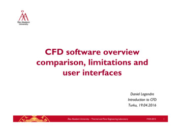
Geometry Clean-up: References from Softwares - HypermeshRemove Small FilletsRemove Interior HolesA powerful technique for finding problem areas is to usethe auto-mesh panel in interactive mode to preview amesh on the surfaces. Use your target element size andreview areas with a node density of 1. These are anindication that the feature may be too small for theelement size you plan on using. This helps identify shortsurface edges to be suppressed or any fixed points thatshould be combined.
Geometry Clean-up: Topological DefinitionAn incongruency problem means that two (or more) surfaces, appearing to have an edge in common, donot share same edge vertices.1. Two points are coincident if they are separated by a distance equal to or less than the global modeltolerance. If, upon creation, two points are coincident, they are considered the same and thesecond point is not created.2. Two surfaces sharing the same edge are topologically congruent. Similarly, any two surfaces notseparated by a distance greater than the global model tolerance are considered to be the same andonly one is created.3. Two solids sharing the same face are topologically congruent.4. When you perform meshing, if the resulting mesh does not match at boundaries between twosurfaces and they appear to be topologically congruent, it is probably because the global modeltolerance was too small at the time the surfaces were created. To prevent this from occurring, werecommend a tolerance of 0.05% of the expected maximum model size. The correct tolerance mayvary, however, based on the size of the smallest mesh element or geometric entity you plan tomodel. If gaps greater than the
Geometry Clean-up: Topological Definitiontolerance exist where geometry should connect, you may need to increase the global modeltolerance. Too large a tolerance value can result in problems with other parts of the model, soconsider carefully before you increase the tolerance.5. CFX-Build determines connectivity (topology) of the model during the creation phase, or via CADaccess or import of geometry. Once connectivity is determined you cannot modify it unless youfirst delete the geometry
At the same time it must address the mathematical constraints under which a CFD software solves the governing Differential Equations. The applicability of “Fully Developed” and “Developing” flow should be carefully thought of while deciding the computational domain. Lets us start with some examples before going into other details. In example below, for Outlet-1, clearly CFD will never .