Transcription
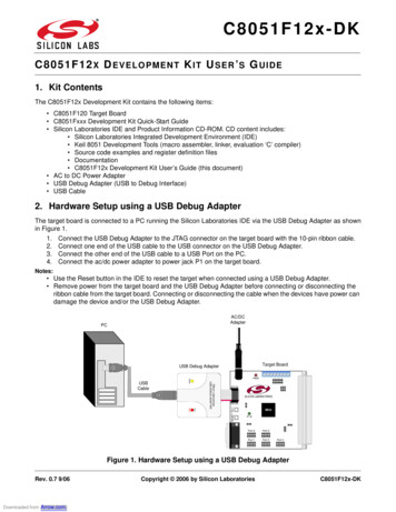
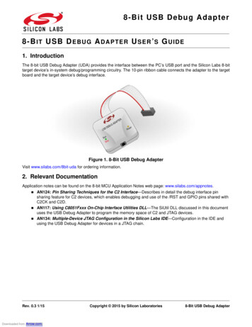
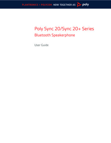
AN13515USB CAN Adapter based on LPC55S16Rev. 0 — 18 January 20221 Introduction1.1 OverviewThis application note aims to build a USB-CAN adapter where the USB dataretransmit to CAN-bus and vice versa. NXP LPC55S16 has a high-speedUSB port and CANFD controllers. HSUSB can reach up to 480 Mbit/stransmission speed, which is enough for transmitting CANFD frame at highestCAN baud rate.To make the system easy to use and compatible with other devices, we useUSB CDC virtual COM port as communication interface with PC and a simpleASCII protocol inherited from open-source project USBtinViewer.2 ImplementationApplication 1Overview. 1Implementation.1Overview. 1Related SDK example. 1Hardware. 2Serial communication protocol.2Hands on with USBtinViewer. 5Connecting hardware toUSBtinViewer.6Third-party and communityresources.9Schematic of USB-CAN-adapter. 10Reference.10Revision history. 102.1 OverviewAs shown in Figure 1, USB CDC uses two USB physical buck endpoints to transfer data between PC and MCU. Each endpointis responsible for uni-directional data transfer.SDK already provides MCAN driver and USB Stack. In software, add two buffers for each pipe, one for USB - CAN bus and theother for CAN bus - USB. To ensure the best performance, the two pipes are independent.Figure 1. System block diagram2.2 Related SDK exampleBefore continuing the task, we need the background knowledge of USB CDC and CAN usage. Fortunately, SDK providestwo examples. MCAN loopback example
NXP SemiconductorsImplementationMCAN example is a simple CAN loopback example which demonstrates usage of LPC54608’s CAN module. This exampleenables the internal loopback of CAN module and send a CAN frame. The CAN frame loops back into CAN receiver and MCUdisplays any received CAN frames on UART terminal. To get familiar with this example, read the readme documentation andrun the example.Example location: \boards\lpcxpresso55s16\driver examples\mcan\loopback usb device cdc vcom exampleThis example is USB CDC class example to enumerate USB as a communication device class. When USB enumerationcompletes, a COM port pops out on the device. Any character sent through this COM port is loop back to display. See thereadme documentation for this example for how to install device driver and run the demo.Example location: \boards\lpcxpresso55s16\usb examples\usb device cdc vcom\bmBe familiar with above two examples before continue reading. Those two examples are building blocks for USB-CANadapter design.2.3 HardwareTable 1 describe GPIO pins used in USB-CAN adapter.Table 1. GPIO pins used in USB-CAN adapterGPIOFunctionDescriptionPIO1 2CAN0 TXCAN bus signalPIO1 3CAN0 RXCAN bus signalUSB1 DMUSB1 DMHSUSB DMUSB1 DPUSB1 DPHSUSB DPPIO0 29UART RXDDebug UART RXDPIO0 30UART TXDDebug UART TXDFor full schematic, see Schematic of USB-CAN-adapter.2.4 Serial communication protocolUSB-CAN adapter registers as a virtual serial port on the host computer. With simple ASCII commands, CAN bus configurationcan be controlled over this serial port. You can send/receive commands from any serial terminal program or from yourown program.Table 2. ASCII protocol commands list:ASCII commandsResponseDescriptionO[CR][CR]Open CAN channelC[CR][CR]Close CAN channeliii: Identifier in hexadecimal format (000-7FF)tiiildd.[CR]Transmit standard (11 bit) frame. l: Data length (0-8)dd: Data byte value in hexadecimal format (00-FF)Table continues on the next page.USB CAN Adapter based on LPC55S16 , Rev. 0, 18 January 2022Application Note2 / 11
NXP SemiconductorsImplementationTable 2. ASCII protocol commands list: (continued)ASCII commandsResponseDescriptionx: Bitrate id (0-8)S0 10 kBaudS1 20 kBaudS2 50 kBaudSx[CR]Set baud rateS3 100 kBaudS4 125 kBaudS5 250 kBaudS6 500 kBaudS7 800 kBaudS8 1 MBaudTiiiiiiiildd.[CR]Transmit extended (29bit) frame.iiiiiiii: Identifier in hexadecimalformat (0000000-1FFFFFFF)l: Data length (0-8) dd:Data byte value in hexadecimal format (00-FF)riiil[CR]Transmit standard RTR (11bit) frame.Riiiiiiiil[CR]Transmit extended RTR (29bit) frame.iii: Identifier in hexadecimal format (000-7FF)l: Data length (0-8)iiiiiiii: Identifier in hexadecimalformat (0000000-1FFFFFFF)l: Data length (0-8)SJA1000 format (AM0.AM3).mxxxxxxxx[CRSet acceptance filter maskOnly first 11bit are relevant.xxxxxxxx: Acceptance filter maskSJA1000 format (AC0.AC3).Mxxxxxxxx[CR]Set acceptance filter code.Only first 11bit are relevant.xxxxxxxx: Acceptance filter codeExample:Set 10 kBaud, open CAN channel, send CAN message (id 001 h, dlc 4, data 11 22 33 44), and close CAN.Table 3. CAN messageCommandResponseS0[CR][CR]O[CR][CR]Table continues on the next page.USB CAN Adapter based on LPC55S16 , Rev. 0, 18 January 2022Application Note3 / 11
NXP SemiconductorsImplementationTable 3. CAN message CR][CR]With a state machine, the software accepts serial stream from CDC port, parses the ASCII, and applies the command. Below listssome of the important code snippet used in the software. For full source code, see AN13515SW. To send a CAN txFrame.dlctxFrame.idtxFrame.datatxFrame.size kMCAN FrameIDStandard;kMCAN FrameTypeData;0;0;len;id STDID OFFSET;buf;CAN DATASIZE;txXfer.frame &txFrame;txXfer.bufferIdx 0;MCAN TransferSendNonBlocking(EXAMPLE MCAN, &mcanHandle, &txXfer); To receive a CAN frame,static void mcan callback(CAN Type *base, mcan handle t *handle, status t status, uint32 tresult, void *userData){switch (status){case kStatus MCAN RxFifo0Idle:{memcpy(rx data, rxFrame.data, rxFrame.size);MCAN TransferReceiveFifoNonBlocking(EXAMPLE MCAN, 0, &mcanHandle, &rxXfer);can rx cb(rxFrame.id STDID OFFSET, rx data, rxFrame.dlc);}break;case kStatus MCAN TxIdle:{}break;default:break;}} To send data via USB CDC,void usbd cdc send(uint8 t *buf, uint32 t len){USB DeviceCdcAcmSend(s cdcVcom.cdcAcmHandle, USB CDC VCOM BULK IN ENDPOINT, buf, len);}USB CAN Adapter based on LPC55S16 , Rev. 0, 18 January 2022Application Note4 / 11
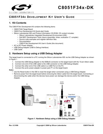
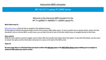
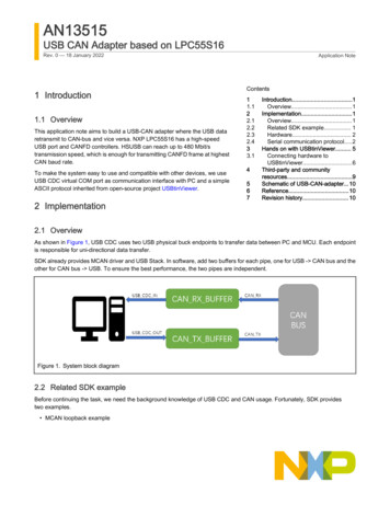
NXP SemiconductorsHands on with USBtinViewer To receive data from USB CDC,usb status t USB DeviceCdcVcomCallback(class handle t handle, uint32 t event, void *param){switch (event){ case kUSB DeviceCdcEventRecvResponse:{if ((1 s cdcVcom.attach) && (1 s cdcVcom.startTransactions)){uint8 t rx size;rx size epCbParam- length;{error USB DeviceCdcAcmRecv(handle, USB CDC VCOM BULK OUT ENDPOINT,cdc rx buf, g c rx cb(cdc rx buf, rx size);}}break;}}3 Hands on with USBtinViewerTo verify the functionality USB-CAN adapter, in this section, we use open-source software USBtinViewer and a commercialUSB-CAN-adapter (PCAN-USB).USBtinViewer can be download from https://www.fischl.de/usbtin/#usbtinviewer.We use PCAN-USB for commercial USB-CAN adapter and busmaster for software.Busmaster can be download from https://rbei-etas.github.io/busmaster/.Figure 2 shows the hardware test environment.USB CAN Adapter based on LPC55S16 , Rev. 0, 18 January 2022Application Note5 / 11
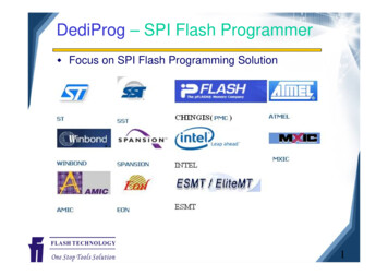
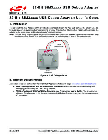
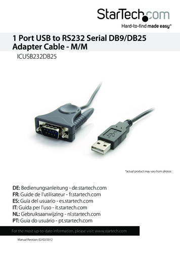
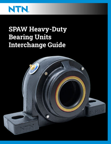
NXP SemiconductorsHands on with USBtinViewerFigure 2. Test environment setup3.1 Connecting hardware to USBtinViewer1. Download USBtinViewer and connect the USB port of USB-CAN-adapter to the PC. A USB CDC COM port pops up.NOTEThe COM port number varies from PC to PC.Figure 3. USB CDC port enumerationOpen USBtinViewer, select COM port and CAN baud rate (500 K in this example). Click Connect, and the USBtinViewerreturns the firmware information, as shown in Figure 4. The information means that connection succeeds.USB CAN Adapter based on LPC55S16 , Rev. 0, 18 January 2022Application Note6 / 11
NXP SemiconductorsHands on with USBtinViewerFigure 4. Connecting USB-CAN adapter to USBtin viewer2. Open busmaster and connect PCAN-USB. Select 500 K baud rate, as shown in Figure 5.Figure 5. Connecting PCAN-USB to busmaster3. Send CAN data from USBtinViewer and received by busmaster.Connect USB-CAN adapter and PCAN-USB. In the CAN TX box, at the bottom of USBtinViewer, enter the CAN messageID, DLC, and data field. Click Send, and the USB-CAN adapter sends the CAN message.USB CAN Adapter based on LPC55S16 , Rev. 0, 18 January 2022Application Note7 / 11
NXP SemiconductorsHands on with USBtinViewerFigure 6. Sending CAN data from USBtinViewer and received by busmasterIn the Message window of busmaster, the same CAN message can be received, as shown in Figure 6.4. Send CAN data from busmaster and verify by USBtinViewer.In busmaster, open Transmit Window. Click the empty space under the Message Name column. Enter the new messagename, DLC, and frame data field. Click Send message, and the busmaster sends the CAN message. On USBtinViewer,this CAN message can be monitored, as shown in Figure 8.Figure 7. Sending CAN data from busmaster and received by USBtinViewerUSB CAN Adapter based on LPC55S16 , Rev. 0, 18 January 2022Application Note8 / 11
NXP SemiconductorsThird-party and community resourcesFigure 8. USBtinViewer received CAN message4 Third-party and community resourcesMany useful third-party resources are available on USBtin web page. It includes libraries and tools supporting USBtin. It providesrich resources and supports varies programming languages.Figure 9. Third-party tools support USBtinUSB CAN Adapter based on LPC55S16 , Rev. 0, 18 January 2022Application Note9 / 11
NXP SemiconductorsSchematic of USB-CAN-adapter5 Schematic of USB-CAN-adapterFigure 10. Schematic of USB-CAN-adapter6 Reference1. https://www.fischl.de/usbtin/#usbtinviewer2. https://rbei-etas.github.io/busmaster/7 Revision historyRev.0DateDescription18 January 2022 Initial releaseUSB CAN Adapter based on LPC55S16 , Rev. 0, 18 January 2022Application Note10 / 11
How To Reach UsHome Page:nxp.comWeb Support:nxp.com/supportLimited warranty and liability — Information in this document is provided solely to enable system and software implementers to use NXPproducts. There are no express or implied copyright licenses granted hereunder to design or fabricate any integrated circuits based onthe information in this document. NXP reserves the right to make changes without further notice to any products herein.NXP makes no warranty, representation, or guarantee regarding the suitability of its products for any particular purpose, nor doesNXP assume any liability arising out of the application or use of any product or circuit, and specifically disclaims any and all liability,including without limitation consequential or incidental damages. “Typical” parameters that may be provided in NXP data sheets and/orspecifications can and do vary in different applications, and actual performance may vary over time. All operating parameters, including“typicals,” must be validated for each customer application by customer's technical experts. NXP does not convey any license underits patent rights nor the rights of others. NXP sells products pursuant to standard terms and conditions of sale, which can be found atthe following address: nxp.com/SalesTermsandConditions.Right to make changes - NXP Semiconductors reserves the right to make changes to information published in this document, includingwithout limitation specifications and product descriptions, at any time and without notice. This document supersedes and replaces allinformation supplied prior to the publication hereof.Security — Customer understands that all NXP products may be subject to unidentified or documented vulnerabilities. Customeris responsible for the design and operation of its applications and products throughout their lifecycles to reduce the effect of thesevulnerabilities on customer’s applications and products. Customer’s responsibility also extends to other open and/or proprietarytechnologies supported by NXP products for use in customer’s applications. NXP accepts no liability for any vulnerability. Customershould regularly check security updates from NXP and follow up appropriately. Customer shall select products with security featuresthat best meet rules, regulations, and standards of the intended application and make the ultimate design decisions regarding itsproducts and is solely responsible for compliance with all legal, regulatory, and security related requirements concerning its products,regardless of any information or support that may be provided by NXP. NXP has a Product Security Incident Response Team(PSIRT) (reachable at PSIRT@nxp.com) that manages the investigation, reporting, and solution release to security vulnerabilities ofNXP products.NXP, the NXP logo, NXP SECURE CONNECTIONS FOR A SMARTER WORLD, COOLFLUX,EMBRACE, GREENCHIP, HITAG,ICODE, JCOP, LIFE, VIBES, MIFARE, MIFARE CLASSIC, MIFARE DESFire, MIFARE PLUS, MIFARE FLEX, MANTIS, MIFAREULTRALIGHT, MIFARE4MOBILE, MIGLO, NTAG, ROADLINK, SMARTLX, SMARTMX, STARPLUG, TOPFET, TRENCHMOS,UCODE, Freescale, the Freescale logo, AltiVec, CodeWarrior, ColdFire, ColdFire , the Energy Efficient Solutions logo, Kinetis,Layerscape, MagniV, mobileGT, PEG, PowerQUICC, Processor Expert, QorIQ, QorIQ Qonverge, SafeAssure, the SafeAssure logo,StarCore, Symphony, VortiQa, Vybrid, Airfast, BeeKit, BeeStack, CoreNet, Flexis, MXC, Platform in a Package, QUICC Engine, Tower,TurboLink, EdgeScale, EdgeLock, eIQ, and Immersive3D are trademarks of NXP B.V. All other product or service names are theproperty of their respective owners. AMBA, Arm, Arm7, Arm7TDMI, Arm9, Arm11, Artisan, big.LITTLE, Cordio, CoreLink, CoreSight,Cortex, DesignStart, DynamIQ, Jazelle, Keil, Mali, Mbed, Mbed Enabled, NEON, POP, RealView, SecurCore, Socrates, Thumb,TrustZone, ULINK, ULINK2, ULINK-ME, ULINK-PLUS, ULINKpro, µVision, Versatile are trademarks or registered trademarks of ArmLimited (or its subsidiaries) in the US and/or elsewhere. The related technology may be protected by any or all of patents, copyrights,designs and trade secrets. All rights reserved. Oracle and Java are registered trademarks of Oracle and/or its affiliates. The PowerArchitecture and Power.org word marks and the Power and Power.org logos and related marks are trademarks and service markslicensed by Power.org. M, M Mobileye and other Mobileye trademarks or logos appearing herein are trademarks of Mobileye VisionTechnologies Ltd. in the United States, the EU and/or other jurisdictions. NXP B.V. 2022.All rights reserved.For more information, please visit: http://www.nxp.comFor sales office addresses, please send an email to: salesaddresses@nxp.comDate of release: 18 January 2022Document identifier: AN13515
Debug UART TXD For full schematic, see Schematic of USB-CAN-adapter. . USB-CAN adapter registers as a virtual serial port on the host computer. With simple ASCII commands, CAN bus configuration can be controlled over this serial port. You can send/receive commands from any serial terminal program or from your own program. Table 2. ASCII .