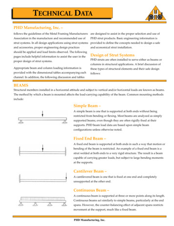
Transcription
ONLINEA GUIDE TO LIFTINGBEAMSAND SPREADERSSelectionSafe useVerificationDesignManufacturea comprehensive guide forspecifiers, buyers, andresponsible persons
OverviewThis easy-to-read and comprehensive guide to lifting beams andspreaders contains information extracted from the LEEA guidance - Theverification of spreader beams, lifting beams and lifting frames.It covers all aspects of the selection, design, manufacture,verification, testing, repair, modification, storage, inspection and safeuse of lifting beams and spreader beams.The table of contents (Next page) lists the sections covered andcontains links to each section. For ease of use, each section is linkedback to the table of contents.Tel: 0845 270 2919 - INT: 00 44 161 223 1990 - Email: sales@dale-lifting.co.uk - Web: www.dlhonline.co.uk1
Table of 2232425TitleWhy use a lifting beam?Lifting beam –v – Lifting spreaderVariationsMaking sure the load is stableMulti-purpose designsStandards for lifting beams and spreadersDocumentationDesign standardTechnical fileVerification methodsVerification through calculationVerification through testLoad testing with weightsLoad testing by means of an applied forceVerification of lifting beam with moving partsVerification of ancillary itemsAttaching the lifting beam to the crane and loadBeam markings and identificationMarkingsConsiderations for headroomStorageInstructions for safe use and maintenanceIn-service inspection of lifting beamsVerification of repairs and modificationsOur ServicesContacting 72829303233Tel: 0845 270 2919 - INT: 00 44 161 223 1990 - Email: sales@dale-lifting.co.uk - Web: www.dlhonline.co.uk2
1. Why use a lifting beam?Lifting beams, frames and spreaders are usually designed and built fora specific purpose. The range of designs and capacities is thereforeonly limited by practicality.It is important to take care in selecting the right type of beam to beused and to plan the lift taking the following into account: Application requirements - to reduce headroom, provide multiplelifting points, to provide adjustable lifting centres, to handle outof balance loads, to remove or control inward or crushing forces,to allow for special load attachments. Calculations to be made will include the capacity, both of theoverall beam and of the loading of the individual lifting points. Another important consideration is the centre of gravity of theload to be lifted, together with any accessories and orattachments used - slings, grabs, shackles, hooks, magnets,vacuum pads etc.(Back to table of contents)Tel: 0845 270 2919 - INT: 00 44 161 223 1990 - Email: sales@dale-lifting.co.uk - Web: www.dlhonline.co.uk3
2.Lifting beam – v – Lifting SpreaderLifting beams, Lifting frames and Lifting spreaders are a means ofproviding two or more lifting points from the hook of the liftingmachine or crane spaced so as to match the position of the liftingpoints on the load. The difference lies in the way the forces aretransmitted.A lifting beam is loaded in bending.Typically a simple lifting beam will have asingle lifting eye above the beam whichengages with the lifting machine hook andlower lifting eyes at points on the undersideof the beam to connect to the load.A spreader, often called a spreader beam,is actually a strut loaded in compression.Typically a simple spreader will have asuspension sling which connects the liftingmachine hook to the ends of the spreaderwhich are then connected to the load. Thisarrangement enables the sling to lift, e.g. Acable reel from its axle whilst preventingthe sling legs damaging the drum flanges.The design of modern spreaders is usually much more sophisticated butthe principle is the same. In practice a combination of beam andspreader is often used and whilst the terms are often usedinterchangeably, the equipment itself is not interchangeable. It mustbe loaded in the manner for which it was designed.(Back to table of contents)Tel: 0845 270 2919 - INT: 00 44 161 223 1990 - Email: sales@dale-lifting.co.uk - Web: www.dlhonline.co.uk4
3. VariationsAnother variation of the lifting beam is one designed to connect twooverhead travelling cranes and provide one or more lifting points.This facilitates tandem lifting.The total lifting capacity canbe that of the two cranes lessthe self-weight of the beamand any allowance foruncertainty in the sharing ofthe load.Most lifting beams and spreaders will bedesigned for specific applications e.g. Alifting beam for use with vacuum pads orlifting magnets to lift long flexible loadswhich needs support at regular intervals topreventsagging.A spreader might be designed to lift a loadsuch as a vehicle or boat, lifting it fromthe base but keeping the slings clear ofeasily damaged areas.Tel: 0845 270 2919 - INT: 00 44 161 223 1990 - Email: sales@dale-lifting.co.uk - Web: www.dlhonline.co.uk5
4. Making sure the load is stableLifting beams and spreaders are often used whenthere is limited headroom. Ideally it is best if theattachment points on the load are above its centre ofgravity as that will ensure that the load will alwayshang in a stable position.However if the lifting beam or spreader is connectedto the load by slings which attach to the load belowits centre of gravity, care is needed to ensure that the load will bestable when lifted.A typical application of thiskind might be a containerlifted from the base. Thelifting beam is connected tothe container base by fourvertical single leg slings.When viewed from the side,the lifting beam, containerand slings form the four sidesof a rectangle.Without triangulation the foursides form a mechanism which can deform into the shape of aparallelogram. That is what happens if the load is unstable and startsto topple.(Continued next page)Tel: 0845 270 2919 - INT: 00 44 161 223 1990 - Email: sales@dale-lifting.co.uk - Web: www.dlhonline.co.uk6
Looked at from the side, thefigure left illustrates the situation.The forces which prevent or causetoppling come from the verticaldistance from the seat of thelifting machine hook to the slingattachment points on the liftingbeam (A) and the distance of thecentre of gravity above theattachment points on the skid (B).The centre of gravity will alwaystry to be as far from the hook aspossible. If (A) is greater than (B)the arrangement will be stable.The larger the difference, themore stable the arrangement willbe. However if (B) is greater than (A), the arrangement will beunstable and will topple. The relationship between dimensions (C) and(D) also affect stability. If (C) is greater than (D) the arrangement willbe less stable.The issue of stability should be considered at the lift planning stageand not left to checking at the time of rigging.The static friction at the pivot points can be sufficient to allow a wellbalanced load to be lifted vertically. However when a travel motion isstarted this can be sufficient to break the frictional grip and, once theload starts to topple, there is no going back.(Continued next page)Tel: 0845 270 2919 - INT: 00 44 161 223 1990 - Email: sales@dale-lifting.co.uk - Web: www.dlhonline.co.uk7
The example described is a four pointlifting arrangement but the sameproblem can occur with otherarrangements.For example a load held by two slingsin basket hitch, one at either endconnected to a straight lifting beam.Viewed end on, the load is heldsecurely with triangulation providedby the basket hitch.However, viewed from the side,there is the rectangular mechanismsupporting the load from below thecentre of gravity with only thefriction between the slings and theload to stabilise it.Lifting beams often have a profiledplate eye to engage with the lifting machine hook. This keepsdimension (A) to a minimum but can cause stability problems for thesetypes of applications. The obvious way to ensure stability is fordimension (A) to be significantly greater than (B) and this is where aspreader, suspended by a sling, often has the advantage over a liftingbeam.Alternatively the combination design previously referred to can beused. In this the beam is suspended from a sling connected part wayalong the beam rather than at the ends. It increases the (A) dimensionand the forces in the beam are a combination of bending andcompression.(Back to table of contents)Tel: 0845 270 2919 - INT: 00 44 161 223 1990 - Email: sales@dale-lifting.co.uk - Web: www.dlhonline.co.uk8
5. Multi-purpose designsLifting beams and spreaders can also be designed for multi-purposeapplications.There are two basicapproaches to this.Lifting beams canhave adjustablelifting points whichcan be moved alongthe beam to suit theparticular load.Spreaders can be made in modules which are assembled into theconfiguration required.Lifting beams andspreaders of these typesmake it cost effective forone off or limitedapplications.Lifting beams can also bedesigned for applicationswhere the load is to beintentionally tilted or where the position of the top suspension eyeneeds to be adjusted to match the centre of gravity of the load.Designs which incorporate adjustable lifting points or tilting facilitiesshould take account of the possible operator errors in not adjusting ortilting accurately.(Back totable ofcontents)Tel: 0845 270 2919 - INT: 00 44 161 223 1990 - Email: sales@dale-lifting.co.uk - Web: www.dlhonline.co.uk9
6. Standards for lifting beams andspreadersThere is a harmonised European Standard, EN 13155, which specifiesthe requirements for lifting beams and spreaders. It deals with allthese variations as well as specifying the fundamental requirements.Buyers are advised to specify this standard.Lifting beams are classified as lifting accessories and fall within thescope of the Supply of Machinery (Safety) Regulations 2008. Thecurrent harmonized standard BSEN13155:2003 A2:2009m: Cranes –Safety – Non Fixed Load lifting attachments. This standard should beadopted as best practice to ensure conformity to the minimumrequirements of the Machinery Directive.Prior to this standard and the Directive there was no specific standardfor the manufacture of Lifting Beams. Manufacturers would often,therefore, work to the requirements of other standards for weldablestructural steels, such as BS 449 and BS 2573.For the verification of lifting beams, the International LabourOrganisations (ILO) code of practice for Safety and Health in Portsincluded a sliding scale of proof forces linked to the capacity of thelifting beam.However these values were not adopted in EN 13155 and, for highercapacities, are in conflict with the minimum requirements of theMachinery Directive.Once in service lifting beams fall under the Provision of Use of WorkEquipment Regulations and the Lifting Operations and LiftingEquipment Regulations (LOLER).(Back to table of contents)Tel: 0845 270 2919 - INT: 00 44 161 223 1990 - Email: sales@dale-lifting.co.uk - Web: www.dlhonline.co.uk10
7. DocumentationLifting beams are classified as lifting accessories and fall within thescope of the Supply of Machinery (Safety) Regulations 2008.It is therefore required that they are supplied with an EC Declarationof Conformity and instructions for use and maintenance (refer to 3.3).The EC Declaration must contain the followinginformation: The name and address of the manufacturer. The name and address of the manufacturers authorisedrepresentative. The name and address of the person responsible for compilingthe technical file. Description of the equipment, Type, serial number, WLL, selfweight (including ancillary equipment, details of the ancillaryequipment supplied attached or to be used with the equipment. Standards and specifications used. Place and date of the declaration. A declaration claiming conformance with the essential health andsafety requirements as defined in the directive 2006/42/EC Name, position and signature of the person making thedeclaration.(Back to table of contents)Tel: 0845 270 2919 - INT: 00 44 161 223 1990 - Email: sales@dale-lifting.co.uk - Web: www.dlhonline.co.uk11
8. DesignWhen designing Lifting Beams and spreaders it is important that theminimum requirements of the Supply of Machinery (Safety) Regulationsare met in full. This part of the guidance will address the criteria thatmust be considered, though it is also recommended that BS EN 13155 isfollowed.(Back to table of contents)9. Technical FileThe technical file is very important and must contain all theinformation that went into the manufacture of the lifting beam.Should a lifting beam fail in service, then it is this technical file thatwill be scrutinised. If it cannot be proven that other factors, such asmisuse, were not to blame for the failure, then it is vital thatinformation within the technical file shows that the manufacturer hasdone everything reasonably practicable to ensure the safety of theequipment.The technical file does not have to be a physical entity, but it must beable to be assembled from various sources should the need arise.See next page for information required.Tel: 0845 270 2919 - INT: 00 44 161 223 1990 - Email: sales@dale-lifting.co.uk - Web: www.dlhonline.co.uk12
Information required for a technicalfileTypical information that should form a technical file for lifting beam isas follows: A list of the EHSRs which apply to the lifting beamA description of the methods used to eliminate hazards or reducerisksA list of standards to which the equipment has been made. Thisshould include standards used for accessories that are suppliedfitted to the beam, such as shackles, chains, wire ropes, etc.Information from the user. This should include such detail as tothe geometry and mass of the load, including the centre ofgravity. Details of the lifting appliance should be included, suchas the size of the hook, the SWL and the work envelope betweenthe appliance and the load is also important.Design information. Calculations, detailed drawings andfabrication
01.01.1993 · 15 Verification of lifting beam with moving parts 20 16 Verification of ancillary items 22 17 Attaching the lifting beam to the crane and load 23 18 Beam markings and identification 24 19 Markings 25 20 Considerations for headroom 26 21 Storage 27 22 Instructions for safe use and maintenance 28 23 In-service inspection of lifting beams 29
