Transcription
EZ-SCREEN SystemInstruction ManualFeatures An optoelectronic safeguarding device Compact package for smaller production machines,robust for large power presses Creates a screen of synchronized, modulatedinfrared sensing beams. Choose from 20 sizes in150 mm (6") increments:– 14 mm (0.55") resolution models with definedareas from 150 mm to 1.2 m (6" to 48")– 30 mm (1.18") resolution models with definedareas from 150 mm to 1.8 m (6" to 71") Remote Test input terminals for simulating a“blocked” condition Easily configured Reduced Resolution (FloatingBlanking) Three-digit display provides diagnostic informationand indicates number of beams blocked Zone indicators identify blocked beams FMEA tested to ensure control reliability Receiver LEDs provide system status andemitter/receiver alignment indications Highly immune to EMI, RFI, ambient light, weldflash, and strobe light Two-piece design with External Device Monitoring Vibration-tolerant, factory burned-in emitter andreceiver circuitry for toughness and dependabilitySection Contents9714 10th Avenue North Minneapolis, MN 55441Phone: 763.544.3164 http://www.bannerengineering.comEmail: sensors@bannerengineering.comPrinted in USASection 1Introduction . . . . . . . . . . . . . . . . . . . . . . . . . . . . . . . .Page 3Section 2System Components and Specifications . . . . . . . . . . .Page 8Section 3Installation and Alignment . . . . . . . . . . . . . . . . . . . . .Page 16Section 4System Operation . . . . . . . . . . . . . . . . . . . . . . . . . . .Page 35Section 5Troubleshooting and Maintenance . . . . . . . . . . . . . . .Page 40Section 6Checkout Procedures . . . . . . . . . . . . . . . . . . . . . . . .Page 4509/03P/N 112852
EZ-SCREENTable of ContentsTable of Contents1. System Overview . . . . . . . . . . . . . . . . . . . . . . . . page 31.1 Introduction . . . . . . . . . . . . . . . . . . . . . . . . . . . . . . . 31.2 Applications and Limitations . . . . . . . . . . . . . . . . . . . 41.3 Control Reliability: Redundancy and Self-Checking . . . 41.4 Operating Features . . . . . . . . . . . . . . . . . . . . . . . . . . 52. System Components and Specifications . . . . . . . . Page 82.1 Emitter and Receiver Models . . . . . . . . . . . . . . . . . . . 82.2 Cables . . . . . . . . . . . . . . . . . . . . . . . . . . . . . . . . . . . . 92.3 Accessories . . . . . . . . . . . . . . . . . . . . . . . . . . . . . . . . 92.4 Replacement Parts . . . . . . . . . . . . . . . . . . . . . . . . . . 122.5 Literature . . . . . . . . . . . . . . . . . . . . . . . . . . . . . . . . . 122.6 Specifications . . . . . . . . . . . . . . . . . . . . . . . . . . . . . . 133. Installation and Alignment . . . . . . . . . . . . . . . . Page 163.1 Mechanical Installation Considerations . . . . . . . . . . . 163.2 Mechanical Mounting Procedure . . . . . . . . . . . . . . . . 233.3 Electrical Connections . . . . . . . . . . . . . . . . . . . . . . . 243.4 Light Screen Initial Checkout . . . . . . . . . . . . . . . . . . . 253.5 Electrical Interface to the Guarded Machine (PermanentHookup) . . . . . . . . . . . . . . . . . . . . . . . . . . . . . . . . . . 293.6 Preparing for System Operation . . . . . . . . . . . . . . . . 314. System Operation . . . . . . . . . . . . . . . . . . . . . . Page 354.1 Security Protocol . . . . . . . . . . . . . . . . . . . . . . . . . . . 354.24.34.44.54.6System Configuration Settings . . . . . . . . . . . . . . . . . 35Reset Procedures . . . . . . . . . . . . . . . . . . . . . . . . . . . 36Status Indicators . . . . . . . . . . . . . . . . . . . . . . . . . . . 37Normal Operation . . . . . . . . . . . . . . . . . . . . . . . . . . . 39Periodic Checkout Requirements . . . . . . . . . . . . . . . 395. Troubleshooting and Maintenance . . . . . . . . . . . Page 405.1 Troubleshooting Lockout Conditions . . . . . . . . . . . . . 405.2 TEST Mode . . . . . . . . . . . . . . . . . . . . . . . . . . . . . . . 435.3 Electrical and Optical Noise . . . . . . . . . . . . . . . . . . . . 445.4 Servicing and Maintenance . . . . . . . . . . . . . . . . . . . . 446. Checkout Procedures . . . . . . . . . . . . . . . . . . . . Page 456.1 Schedule of Checkouts . . . . . . . . . . . . . . . . . . . . . . . 456.2 Commissioning Checkout . . . . . . . . . . . . . . . . . . . . . 456.3 Shift/Daily Checkout . . . . . . . . . . . . . . . . . . . . . . . . . 476.4 Semi-Annual (Six-Month) Checkout . . . . . . . . . . . . . 47Glossary of Terms . . . . . . . . . . . . . . . . . . . . . . . . Page 48Safety Standards and Regulations . . . . . . . Inside Back CoverInstruction ManualImportant .read this page before proceeding!In the United States, the functions that EZ-SCREEN Systems areintended to perform are regulated by the Occupational Safety andHealth Administration (OSHA). Outside of the United States, thesefunctions are regulated by other agencies, organizations, andgovernments. Whether or not any particular EZ-SCREEN Systeminstallation meets all applicable requirements depends uponfactors that are beyond the control of Banner Engineering Corp.These factors include the details of how the EZ-SCREEN System isapplied, installed, wired, operated, and maintained. It is theresponsibility of the purchaser and user to apply this EZSCREEN System in full compliance with all relevant applicableregulations and standards.EZ-SCREEN Systems can guard against accidents only when theyare properly installed and integrated into the machine, properlyoperated, and properly maintained. Banner Engineering Corp. hasattempted to provide complete application, installation, operation,and maintenance instructions. In addition, please direct anyquestions regarding application or use of EZ-SCREEN Systems tothe factory applications department at the telephone number oraddresses shown on the back cover.In addition to OSHA regulations, several other organizationsprovide information about the use of safeguarding devices. Referto the American National Standards Institute (ANSI), the RoboticsIndustries Association (RIA), the Association for ManufacturingTechnology (AMT), and others (see below). Banner EngineeringCorp. makes no claim regarding a specific recommendation of anyorganization, the accuracy or effectiveness of any informationprovided, or the appropriateness of the provided information for aspecific application.The user has the responsibility to ensure that all local, state,and national laws, rules, codes, and regulations relating to theuse of this safeguarding system in any particular applicationare satisfied. Extreme care is urged to ensure that all legalrequirements have been met and that all installation andmaintenance instructions contained in this manual arefollowed.U.S. Standards Applicable to Use of EZ-SCREEN SystemsOSHA 29CFR1910 Occupational Safety and Health StandardsANSI B11 Standards Safeguarding of Machine ToolsANSI/RIA R15.06 Safety Requirements for Robot SystemsNFPA 79 Electrical Standard for Industrial MachinerySee inside back cover for information pertaining toapplicable U.S., European and International standards,and where to acquire copies.Banner Engineering Corp. Minneapolis, U.S.A.2P/N 112852www.bannerengineering.com Tel: 763.544.3164
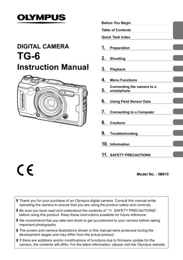
EZ-SCREENSystem OverviewInstruction Manual1. System Overview1.1 IntroductionThe Banner EZ-SCREEN System provides a redundant,microprocessor-controlled, opposed-mode optoelectronic“curtain of light,” or “safety light screen.” It is generally usedas a point-of-operation safeguarding device, and is suited tosafeguard a variety of machinery.EZ-SCREEN Systems are extensively FMEA (Failure Mode andEffects Analysis) tested to establish an extremely high degreeof confidence that when properly installed, no systemcomponent will (even if it should fail) cause a failure todanger.In typical operation, if any part of an operator’s body (or anyopaque object) of more than a pre-determined cross sectionis detected, the OSSD solid-state safety outputs will turn off.These safety outputs are connected to the guarded machine’sFinal Switching Devices (FSDs) that control the primarycontrol elements (MPCEs) which immediately stop the motionof the guarded machine.Electrical connections are made through M12 (or Euro-style)quick-disconnects. The emitter has a 5-pin connector forpower, ground and Test input. The receiver has an 8-pinconnector for power, ground, reset, EDM #1 and #2, andOSSD #1 and #2.Functions such as Trip/Latch select, Reduced Resolution(Floating Blanking), Scan Code select, and External DeviceMonitoring are described in Section 1.4. All models require asupply voltage of 24V dc 15%. Optional interface modulesare also available with 3 N.O. output relays @ 6 amps (IM-T9A) or with 2 N.O. and 1 N.C. output relays @ 6 amps(IM-T-11A).Both emitter and receiver feature 7-segment DiagnosticDisplays and individual LEDs to provide continuous indicationof the System’s operating status, configuration and errorconditions. See Section 1.4.6 for more information.ReceiverThe OSSD (Output Signal Switching Device) safety outputsare capable of performing a “handshake” communication withthe Muteable Safety Stop Interface (MSSI) or Universal SafetyStop Interface (USSI) found on other Banner Engineeringsafety products. The handshake protocol is satisfied by anyBanner Engineering Safety Category 4 (per ISO 13849-1/EN954-1) device with OSSD outputs or MSSI/USSI inputs.This handshake verifies that the interface between the twodevices is capable of detecting certain unsafe failures thatmay occur (such as a short circuit to a secondary source ofpower or to the other channel, high input resistance or loss ofsignal ground).Banner EZ-SCREEN Systems can be described as “two-piece”or “two-box” systems – comprising an emitter and a receiver,but no external controller. The External Device Monitoring(EDM) function ensures the fault detection capability requiredby U.S. Control Reliability and ISO13849-1 Categories 3 and4 without a third box, a controller or a “smart” (i.e., selfchecking) safety module required of systems without EDM.Emitters have a row of synchronized modulated infrared(invisible) light-emitting diodes (LEDs) in a compactrectangular metal housing. Receivers have a correspondingrow of synchronized photodetectors. The dimensions of thelight screen created by the emitter and receiver are called the“defined area”; its width and height are determined by thelength of the sensor pair and the distance between them. Themaximum range is dependent on the resolution, whichdecreases if corner mirrors are used. Emitter and receiverpairs with 14 mm (0.55") resolution have a maximum rangeof 6 m (20'), and pairs with 30 mm (1.18") resolution have amaximum range of 18 m (60').Specified Test Piece(2 diameters suppliedwith receiver)Status indicatorsand configurationswitches behindclear access panelEmitterDefinedAreaQD sconnectCableFigure 1-1. Banner EZ-SCREEN High-Resolution System: emitter,receiver, and two interconnecting cablesBanner Engineering Corp. Minneapolis, U.S.A.www.bannerengineering.com Tel: 763.544.3164P/N 1128523
EZ-SCREENSystem OverviewInstruction Manual1.2 Applications and LimitationsThe Banner EZ-SCREEN system is intended for point-ofoperation machine guarding applications and othersafeguarding applications. It is the user’s responsibility toverify whether the safeguarding is appropriate for theapplication and is installed, as instructed by this manual, by aQualified Person.Before installing the EZ-SCREEN System, read this manualin its entirety, paying particular attention to this sectionand all of Section 3. The System’s ability to perform itssafeguarding function depends upon the appropriateness ofthe application and upon its proper mechanical and electricalinstallation and interfacing to the guarded machine. If allmounting, installation, interfacing, and checkoutprocedures are not followed properly, the System cannotprovide the protection for which it was designed.EZ-SCREEN Systems are typically used, but are not limitedto, the following applications:!The user is responsible for satisfying alllocal, state, and national laws, rules, codes,or regulations relating to the installation and use of thiscontrol system in any particular application. Take extremecare to meet all legal requirements and follow all installationand maintenance instructions contained in this manual.The user has the sole responsibility to ensure that theEZ-SCREEN System is installed and interfaced to theguarded machine by Qualified Persons in accordance withthis manual and applicable safety regulations.Carefully read this manual in its entirety, paying particularattention to Section 1.2 and all of Section 3, before installingthe System. Failure to follow these instructions could resultin serious bodily injury or death. Small assembly equipment Molding presses Automated production equipment Robotic work cells Power pressesEZ-SCREEN Systems may NOT be used with the followingmachinery or unsuitable applications: Any machine that cannot be stopped immediately after astop signal is issued, such as single-stroke (or “fullrevolution”) clutched machinery. Any machine with inadequate or inconsistent machineresponse time and stopping performance. Any machine that ejects materials or component partsthrough the defined area. In any environment that is likely to adversely affectphotoelectric sensing system efficiency. For example,corrosive chemicals or fluids or unusually severe levels ofsmoke or dust, if not controlled, may degrade the efficiencyof the System. As tripping devices to initiate machine motion (PSDIapplications) on mechanical power presses, per OSHAregulation 29 CFR 1910.217.If an EZ-SCREEN System is installed for use as a perimeterguarding system (i.e., where a pass-through hazard mayexist), the dangerous machine motion can be initiated bynormal means only after the safeguarded area is clear ofindividuals and the EZ-SCREEN System has been reset. SeeSection 3.2.1 for further information.Approvals are pending. See www.bannerengineering.com forfurther information.WARNING . . . Read this SectionCarefully Before Installing the System!CAUTION . . . Install System Only onAppropriate ApplicationsBanner EZ-SCREEN Systems are for use only onmachinery that can be stopped immediately aftera stop signal is issued at any point in the machine’s stroke orcycle, such as part-revolution clutched machines. Under nocircumstances may the EZ-SCREEN System be used on fullrevolution clutched machinery or in unsuitable applications asthose listed at left. If there is any doubt about whether or notyour machinery is compatible with the EZ-SCREEN System,contact Banner’s Application Engineers at the factory.1.3 Control Reliability: Redundancy and Self-CheckingRedundancy requires that EZ-SCREEN System circuitcomponents be “backed up” to the extent that, if the failure ofa single component will prevent effective machine stoppingaction when needed, that component must have a redundantcounterpart which will perform the same function. TheEZ-SCREEN System is designed with redundantmicroprocessors.Redundancy must be maintained for as long as theEZ-SCREEN System is in operation. Because a redundantsystem is no longer redundant after a component has failed,the System is designed to monitor itself continuously. Acomponent failure detected by or within the self-checkingsystem causes a “stop” signal to be sent to the guardedmachine and puts the System into a Lockout condition.Recovery from this type of Lockout condition requires: replacement of the failed component (to restoreredundancy) and the appropriate reset procedure (see Section 1.4.7).The Diagnostic Display is used to diagnose causes of aLockout condition (see Section 5.1).Banner Engineering Corp. Minneapolis, U.S.A.4P/N 112852www.bannerengineering.com Tel: 763.544.3164
EZ-SCREENSystem OverviewInstruction Manual1.4 Operating FeaturesThe Banner EZ-SCREEN Systems described by this manualfeature several standard selectable functions: Reduced Resolution (Floating Blanking), Trip or Latch Output, External Device Monitoring (EDM), and Scan Code setting.These functions are configured within the sensors, behind theaccess port on the front of each sensor and in the sensorwiring configuration; see Sections 3.4.2 and 4.2 for moreinformation and configuration DIP switches.The resolution and the maximum range can be determined bythe model number on the emitter and receiver. See Section2.1 for a list of model numbers.1.4.1 Selectable Trip/Latch OutputThe setting for Trip or Latch Output also determines whetherthe System will enter RUN mode automatically or if it willrequire a manual reset first (see Sections 1.4.7 and 4.2). If theSystem is set for Trip Output, other measures must be takento prevent a pass-through hazard; see Section 3.1.2 and thewarning below for more information.!WARNING . Use of Trip/Latch OutputApplication of power to the EZ-SCREENSystem, the clearing of the defined area, orthe reset of a Latch condition MUST NOTinitiate dangerous machine motion. Machine control circuitrymust be designed so that one or more initiation devices mustbe engaged (i.e., a conscious act) to start the machine – inaddition to the EZ-SCREEN System going into RUN mode.Failure to follow these instructions could result in seriousbodily injury or death.If Trip Output is selected, the OSSD outputs will turn ON afterpower is applied, and the receiver passes its internal selftest/synchronization and recognizes that all beams are clear.The Trip Output will also automatically reset after allinterruptions of one or more beams are cleared. If LatchOutput is selected, the EZ-SCREEN requires a manual resetfor the OSSD outputs to turn ON, after power is applied andall beams are clear (see Section 4.5).Figure 1-2. EZ-SCREEN emitter and receiver models1.4.2 External Device Monitoring (EDM)This feature allows the EZ-SCREEN System to monitor thestatus of external devices, such as MPCEs. The choices areOne- or Two-Channel Monitoring, or No Monitoring. EDM isused when the EZ-SCREEN OSSD outputs directly control theenergizing and de-energizing of the MPCEs or other externaldevices; see Sections 3.5.3 and 4.2 for more information.1.4.3 Remote Test InputA pair of wires is provided from the emitter (seeSection 3.5.6) for an external switch, typically a normallyopen contact, held closed. Opening a switch connectedbetween these two terminals “turns off” the emitter,simulating an interruption of one or more light beams. Thisremote Test input may be useful for EZ-SCREEN System setupand to verify machine control circuit operation.1.4.4 Scan Code ConfigurationThe emitter and receiver may be configured to one of twoScan Code positions (1 or 2). Scan codes enable a receiver torecognize beams only from an emitter with the same ScanCode setting. This helps minimize the effects of crosstalkbetween multiple emitter/receiver pairs, and allows multiplepairs to operate in close proximity in certain situations. SeeSections 3.1.5 and 3.1.8 for proper mounting configurations.The Scan Code is set using the selection switch in eachsensor’s configuration port; see Section 4.2 for moreinformation. Both the emitter and its corresponding receivermust be set to the identical setting.Banner Engineering Corp. Minneapolis, U.S.A.www.bannerengineering.com Tel: 763.544.3164P/N 1128525
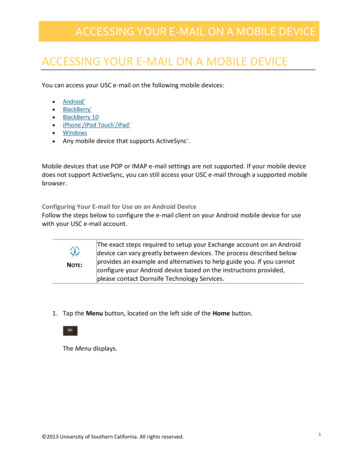
EZ-SCREENSystem OverviewInstruction Manual1.4.5 Reduced Resolution (Floating Blanking)Reduced Resolution increases the minimum diameter of anobject that the light screen can reliably detect anywhere withinits defined area. Reduced Resolution is generally used toallow one or more objects (usually workpiece materials) tomove through the defined area, at any point, without trippingthe OSSD safety outputs.Selecting two-beam Reduced Resolution will reduce theoverall minimum object sensitivity, which allows multipleobjects to move through the defined area (see Section 3.4.2).The effect is every two consecutive beams can be blocked,but not cause a Trip condition (OSSDs turn OFF). This is alsocalled “multiple-point Floating Blanking.”Resolution directly affects the minimum allowable distancebetween the defined area of a light screen and the nearestBeams ofDefined Areahazard point (separation distance, see Section 3.1.1). Thegreen status indicator on the receiver flashes when ReducedResolution is enabled. The ignored object size and resultantReduced Resolution are listed in Section 3.1.1.1.4.6 Status IndicatorsStatus indicators on both the emitter and receiver are clearlyvisible on each sensor’s front panel. Emitter:Bi-color red/green Status indicator – shows whetherpower is applied, and whether the emitter is in RUNmode, TEST mode, or Lockout condition.1-Digit Diagnostic Display – indicates specific error orconfiguration conditions. Receiver:Bi-color red/green Zone indicators – show status of agroup of beams:- aligned and clear, or- blocked and/or misaligned.Yellow Reset indicator – shows System status:- RUN mode or- waiting for a reset.Bi-color red/green Status indicator – shows Systemstatus:- Reduced Resolution enabled,- outputs are ON or OFF, or- the System is in Lockout condition.3-Digit Diagnostic Display – indicates specific error,configuration conditions, or total number of blockedbeams.WorkpiecePress BreakDieSee Sections 4.4 and 5.1 for more information about specificindicator and Diagnostic Display code meanings.Figure 1-3. Reduced one Indicators(each shows statusof approx. 1/8 of thetotal beams)Yellow ResetIndicatorZone 1 Indicator(indicates beamsynchronization status)Status Indicator(Red/Green)Figure 1-4. EZ-SCREEN emitter and receiver status indicatorsBanner Engineering Corp. Minneapolis, U.S.A.6P/N 112852www.bannerengineering.com Tel: 763.544.3164
EZ-SCREENInstruction ManualSystem Overview1.4.7 Manual Resets and Lockout ConditionsReset RoutineThe EZ-SCREEN System requires a manual reset to clear aPower-Up Lockout or Latch condition, and after correcting thecause of a Lockout condition. This function is designed toprovide a “monitored manual reset” (i.e., open-closed-openaction), such that a shorted or tied-down button cannot causea reset. When a key-operated switch is used, this is typicallycalled a key reset.To perform a manual reset, close the normally open switch forat least 1/4 second, but no longer than 2 seconds, and thenre-open the switch. See Sections 3.1.3. and 4.1 for furtherinformation.A Lockout condition will cause the System OSSD outputs toturn OFF. A Lockout condition is indicated by a flashing RedStatus indicator and an error number displayed on theDiagnostic Display. Internal Lockout conditions require amanual reset routine to return the system to RUN mode afterthe failure has been corrected and the input has beencorrectly cycled. A description of possible lockouts, theircauses, and troubleshooting hints are listed in Section 5.Banner Engineering Corp. Minneapolis, U.S.A.www.bannerengineering.com Tel: 763.544.3164P/N 1128527
EZ-SCREENComponents and SpecificationsInstruction Manual2. System Components and SpecificationsAn EZ-SCREEN System includes: An emitter and receiver of equal length, number of beams, and resolution (available separately orin pairs, including mounting hardware), and Two cables.Optional interface module (model IM-T-9A or IM-T-11A), or two positively guided contactors(models 11-BG00-31-D-024, 11BF16C01-024, or user-supplied), and/or optional muting module(model MM-TA-12B) also may be used with the System.2.1 Emitter and Receiver Models14 mm Resolution Models30 mm Resolution Models0.1 m to 6 m (4" to 20') range0.1 m to 18 m (4" to 60') rangeDefined AreaHeightModel150 mm (5.9")300 mm (11.8")450 mm (17.7")600 mm (23.6")750 mm (29.5")900 mm (35.4")1050 mm (41.3")1200 mm (47.2")1350 mm (53.1")1500 mm (59")1650 mm (65")1800 mm rPairNumberof BeamsResponseTime2011 ms4015 ms6019 ms8023 ms10027 ms12032 ms14036 ms16040 rReceiverPairNumberof BeamsResponseTime109 ms2011 ms3013 ms4015 ms5017 ms6019 ms7021 ms8023 ms9025 ms10027 ms11030 ms12032 msBanner Engineering Corp. Minneapolis, U.S.A.8P/N 112852www.bannerengineering.com Tel: 763.544.3164
EZ-SCREENComponents and SpecificationsInstruction Manual2.2 Cables (one 5-pin QD cable for each emitter, one 8-pin for each receiver)ModelNumberLengthWireFor n Color5 m (15')8 m (25')15 m (50')23 m (75')30 m (100')5-pin Eurostyle female22 gauge connector onone end; cut tolengthFor anner CablePinout/Color CodeTermination12345BrWhBuBkGn/YePin Color5 m (15')8 m (25')15 m (50')23 m (75')30 m (100')128-pin Euro3style female422 gauge connector on5one end; cut to6length78BnOr/BkOrWhBkBuGn/YeViFunction 24V dcTest #2OV dcTest #1Gnd/ChassisFunction 24V dcEDM #2EDM #1OSSD #2OSSD #10V dcGnd/ChassisResetEuropean M12Specification*Pin Color12345BrWhBuBkShieldPin Color12345678WhBrGnYeGyPkBuRdConnector(female face view)Function 24V dcTest #20V dcTest #1Gnd/Chassis12543Function 24V dcEDM #2EDM #1OSSD #2OSSD #10V dcGnd/ChassisReset17685234* The European M12 Specification pin assignment and color codes are listed as a customer courtesy. The user must verify suitabilityof these cables for each application.2.3 AccessoriesInterface ModulesProvide isolated safety contacts for the EZ-SCREEN System. See Banner data sheet p/n 62822,and Figures 3-18 and 3-19 for more information.Interface module (3 N/O redundant-output contacts)IM-T-9AInterface module (2 N/O redundant-output contacts, plus 1 N/C auxiliary contact)IM-T-11AContactorsIf used, two contactors per controller are required. (See Figure 3-17.)10 amp positive-guided contactor 3 N/O, 1 NC11-BG00-31-D-02416 amp positive-guided contactor 3 N/O, 1 NC11-BF16C01-024Muting ModuleProvides muting capability for the EZ-SCREEN System. See Banner manual p/n 63517 for furtherinformation.Muting module (2 OSSD outputs, 2 or 4 muting inputs, USSI, override input)MM-TA-12BCable to interface EZ-SCREEN Receiver with MM-TA-12B MutingModule – 22Ga, 8-pin Euro-style (M12) female connector to7-pin Mini-style male connector; double-endedDESE4-508DDESE4-515DDESE4-525D2.5 m (8')5 m (15')8 m (25')Banner Engineering Corp. Minneapolis, U.S.A.www.bannerengineering.com Tel: 763.544.3164P/N 1128529
EZ-SCREENComponents and SpecificationsInstruction ManualMSA Series StandsStand Mirror Length Mirror Length Sensor Length Sensor LengthHeight (Brackets Outward) (Brackets Inward) (Brackets Outward) (Brackets Inward)StandModelPartNumber24"4" to 8"4" to 12"4" to 12"4" to 16"MSA-S24-14317442"4" to 24"4" to 28"4" to 32"4" to 36"MSA-S42-14317566"4" to 48"4" to 48"4" to 48"4" to 48"MSA-S66-14317684"4" to 48"4" to 48"4" to 72"4" to 72"MSA-S84-152397UsableStandHeightPole40 mm(1.58") Squ(4) M10Lens ShieldsBaseNOTE: The total range decreases by approximately 10% per shield.Sensor DefinedArea HeightLens ShieldLengthLens ShieldModel Number6.4 mm (0.25")PartNumber150 mm258 mm (10.2")EZS-15071452300 mm368 mm (14.5")EZS-30071453450 mm518 mm (20.4")EZS-45071454600 mm667 mm (26.3")EZS-60071455750 mm817 mm (32.2")EZS-75071456900 mm967 mm (38.1")EZS-900714571050 mm1116 mm (43.9")EZS-1050714581200 mm1266 mm (49.8")EZS-1200714591350 mm1416 mm (55.7")EZS-1350714601500 mm1565 mm (61.6")EZS-1500714611650 mm1800 mm1715 mm (67.5")1865 mm (73.4")EZS-1650EZS-18007146271463MSM Series Corner MirrorsNOTE: The total sensing range decreases by approximately 8% per mirror.SensorLengthReflective AreaYMountingL1HeightL2267 mm(10.5")356 mm(14")559 mm(22")660 mm(26")267 mm(10.5")356 mm(14")559 mm(22")660 mm(26")323 mm(12.7")411 mm(16.2")615 mm(24.2")716 mm(28.2")292 mm(11.5")381 mm(15")584 mm(23")686 mm(27")864 mm(34")965 mm(38")1168 mm(46")1270 mm(50")864 mm(34")965 mm(38")1168 mm(46")1270 mm(50")919 mm(36.2")1021 mm(40.2")1224 mm(48.2")1326 mm(52.2" )889 mm(35")991 mm(39")1194 mm(47")1295 SM20A43166MSM24A43167M4 x 10 mmScrew(8 supplied)53.8 mm(2.12")YL1L2MSM32A43169MSM36A4317050.8 mm(2.00")MSM44A43172MSM48A4317372.9 mm(2.87")Banner Engineering Corp. Minneapolis, U.S.A.10P/N 112852www.bannerengineering.com Tel: 763.544.3164
EZ-SCREENComponents and SpecificationsInstruction ManualSSM Series Corner MirrorsM6 x 19 mmscrew(4 supplied)101.2 mm(3.98") Rear-surface glass mirrors rated at 85% efficiency for the guarding of multi-sidedapplications with one emitter/receiver pair. Robust construction, two mounting brackets and hardware included.M5 x 10 mmscrew(4 supplied)YL3 EZA-MBK-2 adapter bracket is required for use with MSA Series stand, see page 9. See the specific mirror data sheet or the Banner Safety catalog for further information.L1 Stainless steel reflective surface models also available. See data sheet 67200.L2100 mm(3.94")115 mm(4.53")Note: Brackets may be inverted from thepositions shown a
System Overview EZ-SCREEN Instruction Manual 1.2 Applications and Limitations The Banner EZ-SCREEN system is intended for point-of-operation machine guarding applications and other safeguarding applications. It is the user’s responsibility