Transcription
Table 1a: The complete MSP430 instruction set of 27 core instructionscore instruction mnemonicscore instruction binarySingle-operand arithmetic1501401301211101009RRC Rotate right through carry000100000SWPB Swap bytes000100001RRA Rotate right arithmetic000100010SXT Sign extend byte to word000100011PUSH Push value onto ion9JNE/JNZ Jump if not equal/zero00100010-bit signed offsetJEQ/JZ Jump if equal/zero00100110-bit signed offsetJNC/JLO Jump if no carry/lower00101010-bit signed offsetJC/JHS Jump if carry/higher or same00101110-bit signed offsetJN Jump if negative00110010-bit signed offsetJGE Jump if greater or equal (N V)00110110-bit signed offsetJL Jump if less (N ! V)00111010-bit signed offsetJMP Jump (unconditionally)00111110-bit signed offset151143opcode121 191 0sourceCALL Subroutine call; push PC and move source toPCRETI Return from interrupt; pop SR then pop PCConditional jump; PC PC 2 offsetTwo-operand arithmetic765 4 ceAssource1B/W0Assource1000 0 00008765 4 3210210opcodeMOV Move source to destination0100sourceADD Add source to destination0101sourceADDC Add w/carry: dst (src C)0110sourceSUBC Subtract w/ carry: dst - (src C)0111sourceSUB Subtract; dst - src1000sourceCMP Compare; (dst-src); discard result1001sourceDADD Decimal (BCD) addition: dst src1010sourceBIT Test bits; (dst & src); discard result1011sourceBIC Bit clear; dest & src1100sourceBIS "Bit set" - logical OR; dst src1101sourceXOR Bitwise XOR; dst src1110source1111sourceAND Bitwise AND; dst & src821010-bit signed offset8765 4 stinationAsdestinationAsdestination
The source and destination of an instruction are defined by the following fields:srcThe source operand defined by As and S-regdstThe destination operand defined by Ad and D-regAsThe addressing bits responsible for the addressing mode used for the source (src)S-reg The working register used for the source (src)AdThe addressing bits responsible for the addressing mode used for the destination (dst)D-reg The working register used for the destination (dst)B/WByte or word operation:0: word operation1: byte operationTable 1b: The emulated instructionsemulatedcore instructionsinstructionsADC.x dstADDC.x #0,dstadd carry to destinationCLRCBIC #1,SRclear carry bit0xc312CLRNBIC #4,SRclear negative bit0xc222CLRZBIC #2,SRclear zero bit0xc322DADC.x dstDADD.x #0,dstdecimal add carry to destinationDEC.x dstSUB.x #1,dstdecrementDECD.x dstSUB.x #2,dstdouble decrementDINTBIC #8,SRdisable interrupts0xc232EINTBIS #8,SRenable interrupts0xd232INC.x dstADD.x #1,dstincrementINCD.x dstADD.x #2,dstdouble incrementINV.x dstXOR.x # 1,dstinvertNOPMOV #0,R3no operationPOP dstMOV @SP ,dstpop from stackRETMOV @SP ,PCreturn from subroutineRLA.x dstADD.x dst,dstrotate left arithmetic (shift left 1 bit)RLC.x dstADDC.x dst,dstrotate left through carrySBC.x dstSUBC.x #0,dstsubtract borrow (1 carry) from destinationSETCBIS #1,SRset carry bit0xd312SETNBIS #4,SRset negative bit0xd222SETZBIS #2,SRset zero bit0xd322TST.x dstCMP.x #0,dsttest destination0x43030x4130
Table 2. Summary of addressing modesAs0srcSyntaxDescriptionnRn1nx(Rn)Indexed. The operand is in memory at address Rn x.2n@RnRegister indirect. The operand is in memory at the address held in Rn.3n@Rn Register direct. The operand is the contents of Rn.Indirect autoincrement. As above, then the register is incremented by 1 or 2.Addressing modes using R0 (PC)10(PC)label30(PC)#xSymbolic. x(PC) The operand is in memory at address PC x.Immediate. @PC The operand is the next word in the instruction stream.Addressing modes using R2 (SP) as CG1 and R3 as CG2, constant generation02(SP)-12 (SP)&LABEL22 (SP)#4Constant. The operand is the constant 4.32 (SP)#8Constant. The operand is the constant 8.03(R3)#0Constant. The operand is the constant 0.13 (R3)#1Constant. The operand is the constant 1. There is no index word.23 (R3)#2Constant. The operand is the constant 2.33 (R3)#-1Constant. The operand is the constant -1.register modeAbsolute. The operand is in memory at address x.As/Ad Addressing ModeSyntaxDescription00/0Register modeRnRegister contents are operand01/1Indexed modeX(Rn)(Rn X) points to the operand. X is stored in the next word.01/1Symbolic modeADDR(PC X) points to the operand. X is stored in the next word.Indexed mode X(PC) is used.01/1Absolute mode&ADDR The word following the instruction contains the absolute address.X is stored in the next word. Indexed mode X(SR) is used.10/ Indirect register mode@Rn11/ Indirect autoincrement @Rn Rn is used as a pointer to the operand. Rn is incrementedafterwards by 1 for .B instructions and by 2 for .W instructions.11/ Immediate modeThe word following the instruction contains the immediateconstant N. Indirect autoincrement mode @PC is used.#NRn is used as a pointer to the operand.
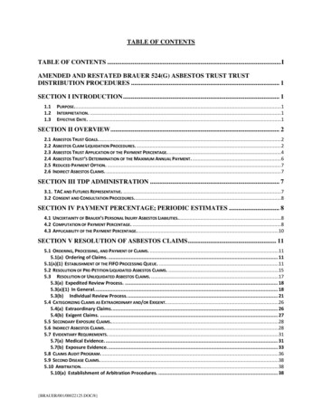
Table 3: Example program layout in memorymemorylocationbyteThe table to the left shows how the binary executableis to be stored in the flash memory. Notice that it isusual to show memory locations with the lowestaddresses at the bottom of the table. The memorylocations available for the program start at f800. Theinformation is organized in 2 bytes words. The lowbyte is stored in a location of the lower address andhigh byte of the word goes into the location with thehigher address in the contiguous flash memory. This iscalled a little-endian format as shown in the table.(The big-endian format stores the high bytes in thelower addresses),. Program code segment growsupward. The stack pointer is set at top of the ram, thebytes pushed into the stack go downward. Vectors arestored in a specially reserved flash memory 4031F80A-.40F2 00F7 002240B2 5A80 01204031 0280 mov#0x280, sp
Table 4: Memory map of G2231address inhexffffmemory mapfunctional blocksusedphysical addressesinterrupt vector table.power-up/mainfffe f800programorg f800ramstack pointer0280 (push pre-decrement;pop post-increment)16-bit peripheralswatchdog timer,0120 5a808-bit peripheralsport 1P1OUT 0021 x.ffe0ffdfflash.f80010ffinformation memory (factory).1000027f.020001ff.010000ff.P1DIR 0022 1.0010000f.0000Special function registers
Table 5: Decimal/Binary/Hexadecimal Reference Tabledecimalbinary, b0x, hexadecimal, hThere are 3 popular ways of representing the numbers used inprogramming: our familiar decimal system, binary system (digits0 and1) and hexadecimal system (digits 0-9,a,b,c,d,e,f). Prefix0x or suffix h is used to indicate hexadecimal numbers, suffix b isused to indicate binary. To convert a number from binary tohexadecimal (see the table) you should group the binary digitsthem into 4-bit groups and assign a hexadecimal digit to eachgroup.When you prepare bit patterns to write into registers the binarynotation, for example 11110111b is much more descriptive thanthe hexadecimal one 0xF3.Executable program is always stored in the computer memory asbinary, to assemble the instruction is to convert them from themnemonics format into binary, to disassemble is the reverseprocess. You will try both during lab 1.00000 00000010000 00010120000 00100230000 00110340000 01000450000 01010560000 01100670000 01110780000 10000890000 100109100000 10100A110000 10110B120000 11000C130000 11010D140000 11100E150000 11110F160001 000010
.
Examples of Dissasembling a Command (using first 3 directives of lab1 program):Instruction 1:It is standard procedure is to initialize the RAM for stack operation using the instruction :mov #0x280, spUse Table 1. To understand the binary format of this instruction shown below. This instructionmoves the hexadecimal number 280 (0x280) to register sp which is a second register in the cpumemory map (Fig.2.),· two-operand move opcode becomes 4 (0100b)· source register (S-reg): we are using here the immediate addressing which means thatthe number is stored directly in the command. It is pointed out by the number in theprogram counter (PC) so that field becomes 0, (0000b). For immediate addressingmode the source register is always PC.· for word bit B/W becomes 0 (this bit is 1 when the instruction deals with bytes of 8bitseach or is 0 if the instruction deals with words of 16bits each)· immediate mode As/Ad becomes 11/- (- means either 0 or 1), consult the table 2 ofaddressing modes· so the field Ad B/W As is 0011b or 0x3 (hexadecimal 3)· destination register (D-Reg) field of sp (stack pointer) is 1· 0280 will be the operand which follows the instructionMOV Move source to destinationMov.b #0x280, spwhich disassemble tobinary01000100S-reg0000Ad0B/W0As1 1D-Reg00014031 0280this hexadecimal number is the instruction in a format ready to send to the flushmemory of the microprocessor.Instruction 2The following instruction will stop the watchdog timer:mov.w # WDTPW WDTHOLD, & WDTCTLWDTPW and WDTHOLD are constants defined in the include file, the symbol indicates thatthey are added to become 0x5A80, When send to the register at the address WDTCTL which ishexadecimal 0120 it stops the watchdog timer.· two-operand move opcode, green columns, becomes 4 · Source in immediate addressing is 0x0· bit B/W becomes 0· immediate mode As/Ad becomes 11/· destination is an absolute address specified in the command, D-Reg field becomes 2.· 5A80 is the word to send to watchdog timer to stop it and 0120 is thewatchdog timer’s absolute address which is the operands which follows theinstruction –MOV Move source to destination0100S-regAdB/WAsD-Reg
mov.w #WDTPW WDTHOLD, &WDTCTL01000000101 1001040B2 5A80 0120 is a 6 byte instruction. It will take 5 cycles of CPU clock to execute.Instruction 3:To assemble the instructionmov.b #11110111b, & P1DIR······two-operand move opcode is 4byte B/W becomes 1 (byte operation)immediate mode As/Ad becomes 11/source S-reg is implied to PC that field becomes 0destination is absolute address , D-Reg becomes 2#N 00f7 (binary 11110111) absolute address 0022 of port P1 direction register will be theoperands which follows the instruction –MOV Move source to destination0100mov.b #11110111b, &P1DIRbinary0100which disassemble toS-reg0000Ad1B/W1As1 1D-Reg001040F2 00F7 0022To assemble the instruction mov.b #0, & P1OUT· We can use exactly the same format as the previous one and obtain: 40F2 0000 0021where 0021 is the address of the P1OUT register· but instead we can use the fact that certain numbers like 0 can be generated by aconstant generation register As becomes 0, S-reg becomes 3, which results in fastermore efficient code.MOV Move source to destination0100mov.b #0, &P1OUTbinary0100which disassemble toS-reg0011Ad1B/W1As0 0D-Reg002043C2 0021 is a 4 byte instruction. It will take 4 cycles of CPU clock to execute.Similarly we can use constant #1 in assembling the instruction bis #1, &P1OUT will yield D3E20021. The list of As values for constant generation using source register 3 is in Table3 2.Values of Constant Generators CG1, CG2 of the MSP430x2xx Family User’s GuideUse the instructions described above with appropriate values of the parameters to create aprogram, which when run by the microprocessor will display first 4 digits of your student numberon the seven segment display.
Instruction 1: It is standard procedure is to initialize the RAM for stack operation using the instruction: mov #0x280, sp Use Table 1. To understand the binary format of this instruction shown below. This instruction moves the hexadecimal number 280 (0x280) to register sp File Size: 238KBPage Count: 9