Transcription
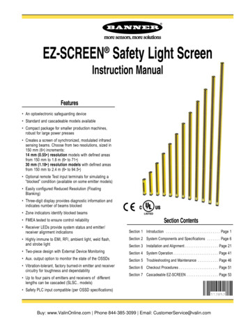
EZ-SCREEN Safety Light Screen Instruction ManualFeatures An optoelectronic safeguarding device Standard and cascadeable models available Compact package for smaller production machines,robust for large power presses Creates a screen of synchronized, modulated infraredsensing beams. Choose from two resolutions, sized in150 mm (6 ) increments:14 mm (0.55 ) resolution models with defined areasfrom 150 mm to 1.8 m (6 to 71 )30 mm (1.18 ) resolution models with defined areasfrom 150 mm to 2.4 m (6 to 94.5 ) Optional remote Test input terminals for simulating a“blocked” condition (available on some emitter models) Easily configured Reduced Resolution (FloatingBlanking) Three-digit display provides diagnostic information andindicates number of beams blocked Zone indicators identify blocked beams FMEA tested to ensure control reliability Receiver LEDs provide system status and emitter/receiver alignment indicationsCRUSNIPF(7)UL1998, UL61496Section ContentsSection 1 Introduction . . . . . . . . . . . . . . . . . . . . . . . . . . . . . Page 1 Highly immune to EMI, RFI, ambient light, weld flash,and strobe lightSection 2 System Components and Specifications . . . . . . . Page 6 Two-piece design with External Device MonitoringSection 4 System Operation . . . . . . . . . . . . . . . . . . . . . . . . Page 41 Aux. output option to monitor the state of the OSSDs Vibration-tolerant, factory burned-in emitter and receivercircuitry for toughness and dependability Up to four pairs of emitters and receivers of differentlengths can be cascaded (SLSC. models)Section 3 Installation and Alignment . . . . . . . . . . . . . . . . . . Page 21Section 5 Troubleshooting and Maintenance . . . . . . . . . . . Page 46Section 6 Checkout Procedures . . . . . . . . . . . . . . . . . . . . . Page 51Section 7 Cascadeable EZ-SCREEN . . . . . . . . . . . . . . . . . Page 53 Safety PLC input compatible (per OSSD specifications)Buy: www.ValinOnline.com Phone 844-385-3099 Email: CustomerService@valin.com
Table of ContentsEZ-SCREENInstruction Manual1. System Overview. . . . . . . . . . . . . . . . . . . . . . . . . . . . . . . . . . . . . . page 11.11.21.31.4Introduction . . . . . . . . . . . . . . . . . . . . . . . . . . . . . . . . . . . . . . . . . . . . . .Applications and Limitations . . . . . . . . . . . . . . . . . . . . . . . . . . . . . . . . .Control Reliability: Redundancy and Self-Checking. . . . . . . . . . . . . . .Operating Features. . . . . . . . . . . . . . . . . . . . . . . . . . . . . . . . . . . . . . . .12232. System Components and Specifications . . . . . . . . . . . . . . . . . Page 62.12.22.32.42.52.62.7Emitter and Receiver Models – 14 mm . . . . . . . . . . . . . . . . . . . . . . . . 7Emitter and Receiver Models – 30 mm . . . . . . . . . . . . . . . . . . . . . . . . 8Cables. . . . . . . . . . . . . . . . . . . . . . . . . . . . . . . . . . . . . . . . . . . . . . . . . . 9Accessories. . . . . . . . . . . . . . . . . . . . . . . . . . . . . . . . . . . . . . . . . . . . . 10Replacement Parts . . . . . . . . . . . . . . . . . . . . . . . . . . . . . . . . . . . . . . . 16Literature. . . . . . . . . . . . . . . . . . . . . . . . . . . . . . . . . . . . . . . . . . . . . . . 16Specifications . . . . . . . . . . . . . . . . . . . . . . . . . . . . . . . . . . . . . . . . . . . 173. Installation and Alignment . . . . . . . . . . . . . . . . . . . . . . . . . . . . . Page 213.13.23.33.43.53.63.7Mechanical Installation Considerations . . . . . . . . . . . . . . . . . . . . . . . 21Mechanical Mounting Procedure . . . . . . . . . . . . . . . . . . . . . . . . . . . . 28Initial Electrical Connections. . . . . . . . . . . . . . . . . . . . . . . . . . . . . . . . 29Light Screen Initial Checkout . . . . . . . . . . . . . . . . . . . . . . . . . . . . . . . 30Electrical Interface to the Guarded Machine (PermanentHookup) . . . . . . . . . . . . . . . . . . . . . . . . . . . . . . . . . . . . . . . . . . . 34Preparing for System Operation . . . . . . . . . . . . . . . . . . . . . . . . . . . . . 38Sensor “Swapability” and the Optional Emitter Hookup . . . . . . . . . . . .384. System Operation . . . . . . . . . . . . . . . . . . . . . . . . . . . . . . . . . . . . Page 414.14.24.34.44.54.6Security Protocol. . . . . . . . . . . . . . . . . . . . . . . . . . . . . . . . . . . . . . . . .System Configuration Settings . . . . . . . . . . . . . . . . . . . . . . . . . . . . . .Reset Procedures . . . . . . . . . . . . . . . . . . . . . . . . . . . . . . . . . . . . . . . .Status Indicators . . . . . . . . . . . . . . . . . . . . . . . . . . . . . . . . . . . . . . . . .Normal Operation . . . . . . . . . . . . . . . . . . . . . . . . . . . . . . . . . . . . . . . .Periodic Checkout Requirements . . . . . . . . . . . . . . . . . . . . . . . . . . . .4141424346465. Troubleshooting and Maintenance. . . . . . . . . . . . . . . . . . . . . . Page 475.15.25.35.4Troubleshooting Lockout Conditions. . . . . . . . . . . . . . . . . . . . . . . . . .Test Mode . . . . . . . . . . . . . . . . . . . . . . . . . . . . . . . . . . . . . . . . . . . . . .Electrical and Optical Noise . . . . . . . . . . . . . . . . . . . . . . . . . . . . . . . .Servicing and Maintenance . . . . . . . . . . . . . . . . . . . . . . . . . . . . . . . .475051516. Checkout Procedures. . . . . . . . . . . . . . . . . . . . . . . . . . . . . . . . . Page 526.16.26.36.4Schedule of Checkouts. . . . . . . . . . . . . . . . . . . . . . . . . . . . . . . . . . . .Commissioning Checkout . . . . . . . . . . . . . . . . . . . . . . . . . . . . . . . . . .Shift/Daily Checkout . . . . . . . . . . . . . . . . . . . . . . . . . . . . . . . . . . . . . .Semi-Annual (Six-Month) Checkout . . . . . . . . . . . . . . . . . . . . . . . . . .525253537. Cascadeable EZ-SCREEN . . . . . . . . . . . . . . . . . . . . . . . . . . . . . .Page 547.17.27.37.47.57.67.77.87.9Overview of Cascading. . . . . . . . . . . . . . . . . . . . . . . . . . . . . . . . . . . . 54Cascadeable Emitter and Receiver Models – 14 mm . . . . . . . . . . . . 55Cascadeable Emitter and Receiver Models – 30 mm . . . . . . . . . . . . 56Determining Interconnect Cable Lengths . . . . . . . . . . . . . . . . . . . . . . 57Response Time for Cascaded Light Screens . . . . . . . . . . . . . . . . . . . 59Cascaded Sensor Configuration Settings. . . . . . . . . . . . . . . . . . . . . . 61Programming for Cascaded Operation. . . . . . . . . . . . . . . . . . . . . . . . 61E-Stop Buttons and Rope/Cable Pulls . . . . . . . . . . . . . . . . . . . . . . . . 62Positive-Opening Safety Interlock Switches . . . . . . . . . . . . . . . . . . . . .63Important .read this page before proceeding!In the United States, the functions that EZ-SCREEN is intendedto perform are regulated by the Occupational Safety and HealthAdministration (OSHA). Outside of the United States, thesefunctions are regulated by other agencies, organizations, andgovernments. Whether or not any particular EZ-SCREENinstallation meets all applicable requirements depends uponfactors that are beyond the control of Banner Engineering Corp.These factors include the details of how the EZ-SCREEN isapplied, installed, wired, operated, and maintained. It is theresponsibility of the purchaser and user to apply thisEZ-SCREEN System in full compliance with all relevantapplicable regulations and standards.EZ-SCREEN can guard against accidents only when it isproperly installed and integrated into the machine, properlyoperated, and properly maintained. Banner Engineering Corp.has attempted to provide complete application, installation,operation, and maintenance instructions. In addition, pleasedirect any questions regarding application or use of EZ-SCREENto the factory applications department at the telephone numberor addresses shown on the back cover.In addition to OSHA regulations, several other organizationsprovide information about the use of safeguarding devices.Refer to the American National Standards Institute (ANSI),the Robotics Industries Association (RIA), the Association forManufacturing Technology (AMT), and others (see below).Banner Engineering Corp. makes no claim regarding aspecific recommendation of any organization, the accuracy oreffectiveness of any information provided, or the appropriatenessof the provided information for a specific application.The user has the responsibility to ensure that all local, state,and national laws, rules, codes, and regulations relatingto the use of this safeguarding system in any particularapplication are satisfied. Extreme care is urged to ensurethat all legal requirements have been met and that allinstallation and maintenance instructions contained in thismanual are followed.U.S. Standards Applicable to Use of EZ-SCREENGlossary of Terms. . . . . . . . . . . . . . . . . . . . . . . . . . . . . . . . . . . . . . . . Page 65Safety Standards and Regulations . . . . . . . . . . . . . . . . Inside Back CoverOSHA 29CFR1910 Occupational Safety and Health StandardsANSI B11 Standards Safeguarding of Machine ToolsANSI/RIA R15.06 Safety Requirements for Robot SystemsNFPA 79 Electrical Standard for Industrial MachinerySee inside back cover for information pertaining toapplicable U.S., European and International standards,and where to acquire copies.Buy: www.ValinOnline.com Phone 844-385-3099 Email: CustomerService@valin.com
EZ-SCREENInstruction ManualOverviewOverview1. System Overview1.1 IntroductionThe Banner EZ-SCREEN provides a redundant, microprocessorcontrolled, opposed-mode optoelectronic “curtain of light,” or“safety light screen.” It typically is used for point-of-operationsafeguarding, and is suited to safeguard a variety of machinery.EZ-SCREEN is extensively FMEA (Failure Mode and EffectsAnalysis) tested to establish an extremely high degree ofconfidence that when properly installed, no system componentwill (even if it should fail) cause a failure to danger.In typical operation, if any part of an operator’s body (or anyopaque object) of more than a pre-determined cross sectionis detected, the OSSD solid-state safety outputs will turn off.These safety outputs are connected to the guarded machine’sFinal Switching Devices (FSDs) that control the primary controlelements (MPCEs), which immediately stop the motion of theguarded machine.The OSSD (Output Signal Switching Device) safety outputsare capable of performing a “handshake” communication withthe Muteable Safety Stop Interface (MSSI) or Universal SafetyStop Interface (USSI) found on other Banner Engineering safetyproducts.Electrical connections are made through M12 (or Euro-style)quick-disconnects. Some emitter models have a 5-pin connectorfor power and the Test function. Other emitters and all receivershave an 8-pin connector for power, ground, inputs and outputs.Functions such as Trip/Latch select, Display Invert, Cascading,Fixed Blanking, Reduced Resolution (Floating Blanking), ScanCode select, and External Device Monitoring are described inSection 1.4. All models require a supply voltage of 24V dc 15%. See Section 2.4 for interfacing solutions.Both emitter and receiver feature 7-segment DiagnosticDisplays and individual LEDs to provide continuous indicationof the EZ-SCREEN’s operating status, configuration and errorconditions. See Section 1.4.7 for more information.This manual contains numerous WARNING and CAUTIONstatements. Warnings refer to situations that could lead tosignificant or serious personal injury or death. Cautions refer tosituations that could lead to slight personal injury or potentialdamage to equipment.Banner EZ-SCREEN is a two-piece (“two-box”) system –comprising an emitter and a receiver, but no external controller.The External Device Monitoring (EDM) function ensures thefault detection capability required by U.S. Control Reliability andISO13849-1 Categories 3 and 4 without a third box, a controlleror a “smart” (i.e., self-checking) safety module required ofsystems without EDM.An auxiliary (aux.) output may be used to signal the state of theOSSDs to a process controller; see Section 1.4.3.Emitters have a row of synchronized modulated infrared(invisible) light-emitting diodes (LEDs) in a compact rectangularmetal housing. Receivers have a corresponding row ofsynchronized photodetectors. The dimensions of the light screencreated by the emitter and receiver are called the “definedarea”; its width and height are determined by the length of thesensor pair and the distance between them. The maximumrange is dependent on the resolution; range decreases if cornermirrors are used. Emitter and receiver pairs with 14 mm (0.55")resolution have a maximum range of 6 m (20'), and pairs with 30mm (1.18") resolution have a maximum range of 18 m (60').Figure 1-1. A typical EZ-SCREEN application: weld cellBuy: www.ValinOnline.com Phone 844-385-3099 Email: CustomerService@valin.com
Overview1.2 Applications and LimitationsThe Banner EZ-SCREEN is intended for point-of-operationmachine guarding applications and other safeguardingapplications. It is the user’s responsibility to verify whether thesafeguarding is appropriate for the application and is installed,as instructed by this manual, by a Qualified Person.Before installing the EZ-SCREEN, read this manual in itsentirety, paying particular attention to this section and all ofSection 3. The EZ-SCREEN’s ability to perform its safeguardingfunction depends upon the appropriateness of the applicationand upon its proper mechanical and electrical installationand interfacing to the guarded machine. If all mounting,installation, interfacing, and checkout procedures are notfollowed properly, the EZ-SCREEN cannot provide theprotection for which it was designed.EZ-SCREEN is typically used, but is not limited to, thefollowing applications: Small assembly equipment Molding and power presses Automated production equipment Robotic work cells Assembly and packaging machines Lean manufacturing systemsEZ-SCREEN may NOT be used with the following machineryor unsuitable applications: Any machine that cannot be stopped immediately after a stopsignal is issued, such as single-stroke (or “full-revolution”)clutched machinery. Any machine with inadequate or inconsistent machineresponse time and stopping performance. Any machine that ejects materials or component parts throughthe defined area. In any environment that is likely to adversely affectphotoelectric sensing efficiency. For example, corrosivechemicals or fluids or unusually severe levels of smoke ordust, if not controlled, may degrade sensing efficiency. As a tripping device to initiate or reinitiate machine motion(PSDI applications), unless the machine and its control systemfully comply with the relevant standard or regulation (seeOSHA 29CFR1910.217, ANSI/NFPA 79, ANSI B11, ANSI/RIA R15.06, ISO 12100, IEC 60204-1, IEC 61496, or otherappropriate standard).If an EZ-SCREEN is installed for use as a perimeter guard(i.e., where a pass-through hazard may exist), the dangerousmachine motion can be initiated by normal means onlyafter the safeguarded area is clear of individuals and theEZ-SCREEN has been manually reset. See Section 3.1.2.EZ-SCREENInstruction ManualWARNING . . . Read this Section CarefullyBefore Installing the SystemThe user is responsible for satisfying all local, state, and nationallaws, rules, codes, or regulations relating to the installation anduse of this control system in any particular application. Takeextreme care to meet all legal requirements and follow all installationand maintenance instructions contained in this manual.The user has the sole responsibility to ensure that theEZ-SCREEN is installed and interfaced to the guarded machineby Qualified Persons in accordance with this manual andapplicable safety regulations.Carefully read this manual in its entirety, paying particular attention toSection 1.2 and all of Section 3, before installing the System. Failureto follow these instructions could result in serious bodily injuryor death.WARNING . . . Install EZ-SCREEN Only onAppropriate ApplicationsBanner EZ-SCREEN is for use only on machinery that can bestopped immediately after a stop signal is issued at any point inthe machine’s stroke or cycle, such as part-revolution clutchedmachines. Under no circumstances may EZ-SCREEN be usedon full-revolution clutched machinery or in unsuitable applicationsas those listed at left. If there is any doubt about whether ornot your machinery is compatible with EZ-SCREEN, contactBanner’s Application Engineers at the factory.1.3 Control Reliability: Redundancy and Self-CheckingRedundancy requires that EZ-SCREEN System circuitcomponents be “backed up” to the extent that, if the failure ofa single component will prevent effective machine stoppingaction when needed, that component must have a redundantcounterpart which will perform the same function. TheEZ-SCREEN is designed with redundant microprocessors.Redundancy must be maintained for as long as the EZ-SCREENis in operation. Because a redundant system is no longerredundant after a component has failed, EZ-SCREEN isdesigned to monitor itself continuously. A component failuredetected by or within the self-checking system causes a“stop” signal to be sent to the guarded machine and puts theEZ-SCREEN into a Lockout condition.Recovery from this type of Lockout condition requires: replacement of the failed component (to restore redundancy)and the appropriate reset procedure (see Section 1.4.8).The Diagnostic Display is used to diagnose causes of a Lockoutcondition (see Section 5.1).Buy: www.ValinOnline.com Phone 844-385-3099 Email: CustomerService@valin.com
EZ-SCREENInstruction Manual1.4 Operating FeaturesOverviewOverview1.4.2 Emitter QD and Hookup OptionsThe Banner EZ-SCREEN models described by this manualfeature several standard selectable functions: Reduced Resolution (Floating Blanking), Trip or Latch Output, External Device Monitoring (EDM), Auxiliary Output, Scan Code setting, Fixed Blanking, Inverted Display, and Cascading (available on SLSC. models).An EZ-SCREEN emitter with an 8-pin connector can beconnected to its own power supply or to the receiver cablecolor-for-color (see Figures 3-19 and 3-20). The color-forcolor hookup allows the emitter and receiver positions to beinterchanged without rewiring.These functions are configured within the sensors, behind theaccess cover on the front of each sensor and in the sensorwiring configuration; see Sections 3 and 4.2 for more informationand configuration DIP switches.This feature allows the EZ-SCREEN System to monitor thestatus of external devices, such as MPCEs. The choices are1- or 2-channel monitoring, or no monitoring. EDM is used whenthe EZ-SCREEN OSSD outputs directly control the MPCEs orother external devices; see Sections 3.5.3 and 4.2 for moreinformation.The resolution and the maximum range can be determined bythe model number on the emitter and receiver. See Section 2 fora list of model numbers.1.4.1 Selectable Trip/Latch OutputThe setting for Trip or Latch Output also determines whether theSystem will enter RUN mode automatically or if it will require amanual reset first (see Sections 1.4.8 and 4.2). If the System isset for Trip Output, other measures must be taken to prevent apass-through hazard; see Section 3.1.2 and the warning belowfor more information.If Trip Output is selected, the OSSD outputs will turn ON afterpower is applied, and the receiver passes its internal self-test/synchronization and recognizes that all beams are clear. TheTrip Output will also automatically reset after all beams arecleared. If Latch Output is selected, the EZ-SCREEN requiresa manual reset for the OSSD outputs to turn ON, after power isapplied and all beams are clear (see Section 4.5).WARNING . . . Use of Trip/Latch OutputApplication of power to the EZ-SCREEN components, theclearing of the defined area, or the reset of a Latch conditionMUST NOT initiate dangerous machine motion. Machine controlcircuitry must be designed so that one or more initiation devicesmust be engaged (i.e., a conscious act) to start the machine – inaddition to the EZ-SCREEN going into RUN mode. Failure to followthese instructions could result in serious bodily injury or death.NOTE: An EZ-SCREEN emitter with 5-pin connector and Testfunction (see Section 1.4.4) is not capable of the colorfor-color hookup.1.4.3 External Device Monitoring (EDM)Auxiliary (Aux.) OutputAn aux. output function is available when the receiver isconfigured for 1-channel EDM (for receivers with date code0834 or newer). This current sourcing (PNP) solid-state output(75 mA max.) is used for control functions that are not safetyrelated. A typical use is to signal the state of the OSSDs to aprogrammable logic controller (PLC). The aux. output followsthe state of the OSSDs. Pin 2 (orange/black) supplies theconnection; see Section 3.5.5 and Figure 3-23.1.4.4 Remote Test InputOn 5-pin EZ-SCREEN emitter models (model numbers SLSE.-.Q5; see Tables 2.1 and 2.2), a Test function is provided. A pairof wires is connected from the emitter (see Section 3.5.6) to anexternal switch, typically a normally open contact, held closed.Opening a switch connected between these two terminals “turnsoff” the emitter, simulating an interruption of one or more lightbeams. This remote Test input may be useful for EZ-SCREENSystem setup and to verify machine control circuit operation.1.4.5 Scan Code ConfigurationThe emitter and receiver may be configured to one of twoScan Code positions (1 or 2). Scan codes enable a receiverto recognize beams only from an emitter with the same ScanCode setting. This helps minimize the effects of crosstalkbetween multiple emitter/receiver pairs, and allows multiplepairs to operate in close proximity in certain situations. SeeSections 3.1.5 and 3.1.8 for proper mounting configurations.The Scan Code is set using the selection switch in eachsensor’s configuration port; see Section 4.2 for moreinformation. Both the emitter and its corresponding receivermust be set to the identical setting.Buy: www.ValinOnline.com Phone 844-385-3099 Email: CustomerService@valin.com
EZ-SCREENInstruction ManualOverview1.4.6 Reduced Resolution (Floating Blanking)Reduced Resolution increases the minimum diameter of anobject that the light screen can reliably detect anywhere withinits defined area. Reduced Resolution is generally used to allowone or more objects (usually workpiece materials) to movethrough the defined area, at any point, without tripping theOSSD safety outputs.Selecting two-beam Reduced Resolution will reduce the overallminimum object sensitivity, which allows multiple objects tomove through the defined area (see Section 3.4.2). The effectis that every two consecutive beams (except for the sync beam)can be blocked, but not cause the OSSDs to turn OFF. This isalso called “Multiple-Point Floating Blanking.”Beams ofDefined AreaResolution directly affects the minimum allowable distancebetween the defined area of a light screen and the nearesthazard point (separation distance, see Section 3.1.1). Thegreen status indicator on the receiver flashes when ReducedResolution is enabled. The ignored object size and resultantReduced Resolution are listed in Section 3.4.2.1.4.7 Status IndicatorsStatus indicators on both the emitter and receiver are clearlyvisible on each sensor’s front panel. Emitter:Bi-color red/green Status indicator – shows whether power isapplied, and whether the emitter is in RUN mode, TEST mode,or Lockout condition.1-Digit Diagnostic Display – indicates specific error orconfiguration conditions. Receiver:Bi-color red/green Zone indicators – show status of a group ofbeams:- aligned and clear (green ON), or- blocked and/or misaligned (red ON), or- fixed blanked area (flashing green).Yellow Reset indicator – shows System status:- RUN mode (ON) or- waiting for a reset (flashing).Bi-color red/green Status indicator – shows System status:- Reduced Resolution enabled (flashing green),- outputs are ON or OFF (green ON or red ON), or- the System is in Lockout condition (flashing red).WorkpiecePress BreakDie3-Digit Diagnostic Display – indicates specific error,configuration conditions, or total number of blocked beams.Figure 1-2. Reduced ResolutionSee Sections 4.4 and 5.1 for more information about specificindicator and Diagnostic Display code ne Indicators(each showsstatus of approx.1/8 of the totalbeams)1-digitDiagnosticDisplayYellow ResetIndicatorStatus IndicatorStatus Indicator(Red/Green)(Red/Green)Zone 1 Indicator(indicates beam synchronization status)Figure 1-3. EZ-SCREEN emitter and receiver status indicatorsBuy: www.ValinOnline.com Phone 844-385-3099 Email: CustomerService@valin.com
EZ-SCREENInstruction Manual1.4.8 Manual Resets and Lockout ConditionsReset RoutineThe EZ-SCREEN requires a manual reset to clear a PowerUp Lockout or Latch condition, and after correcting the causeof a Lockout condition. This function is designed to provide a“monitored manual reset” (i.e., open-closed-open action), suchthat a shorted or tied-down button cannot cause a reset. When akey-operated switch is used, this is typically called a key reset.To perform a manual reset, close the normally open switch forat least 1/4 second, but no longer than 2 seconds, and thenre-open the switch. See Sections 3.1.3 and 4.3 for furtherinformation.A Lockout condition will cause the EZ-SCREEN OSSD outputsto turn OFF. A Lockout condition is indicated by a flashingRed Status indicator and an error number displayed on theDiagnostic Display. Internal Lockout conditions require amanual reset routine to return the system to RUN mode afterthe failure has been corrected and the input has been correctlycycled. A description of possible lockouts, their causes, andtroubleshooting hints are listed in Section 5.Trip Output/Auto ResetWhile the use of a reset switch is recommended, it is notrequired for receivers configured for Trip Output (automaticreset). Cycling the supply power (OFF for 2 seconds, then ON)will also clear lockouts if their cause has been corrected. If areset switch is not used, leave pin 8 (violet wire) not connected(open) and secure it against shorting to a source of power orground.1.4.9 Fixed BlankingThe fixed blanking feature allows for a stationary object(s),such as tooling, to be ignored while it remains positioned inthe defined area. A flashing Green Zone indicator denotes thelocation of a blanked area. If the object is moved or removed,the System goes into a lockout mode. This ensures that anunexpected hole in the sensing field is not created.OverviewOverview1.4.10 Inverted DisplayA push button, located under the access cover, can be used toinvert the display. This is desirable when an emitter and receiverare mounted with the QD connector ends up. A replacementaccess cover with an inverted label is included with each emitterand receiver to accommodate inverted mounting. (See Section4.4).1.4.11 Cascadeable ModelsEmitter and receiver models SLSC.* (see Section 7) arecapable of interconnecting up to four emitter/receiver pairs –regardless of the resolution, the total number of beams, or thesize of the defined area. EZ-SCREEN cascadeable models canalso be used individually as stand-alone systems.Special cabling is not required, but the double-ended 22 awgcordsets listed in Section 2.3 are recommended. See Section7.4 for maximum cable lengths. Pigtail QD models may be usedto reduce the number of required cables.Response time is dependent on the number of beams in thelight screen, and the light screen’s position in the cascade.Maximum system response time can be calculated easily forthese cascaded systems, in two ways: Individually for each light screen in the cascade (separationdistance is calculated for each light screen in the cascade), or Based on the worst-case maximum for the entire cascade(all light screens in the cascade have the same separationdistance).See Section 7.5 for more information.*Models SLSC.-150. not available.Fixed blanking is easily programmed, simply by positioning theobjects, flipping two DIP switches and resetting the System, asdescribed in Section 3.4.3.Buy: www.ValinOnline.com Phone 844-385-3099 Email: CustomerService@valin.com
EZ-SCREENInstruction ManualOverview ions2. Components and SpecificationsAn EZ-SCREEN System includes a compatible emitter and receiver (equal length andresolution; available separately or in pairs), and two cables. Mounting hardware isincluded with each emitter and receiver. Interfacing solutions include IM-T-. modules,redundant positively guided contactors, or an optional muting module; see Section 2.4.Standard models (as listed in the following tables) feature a yellow painted aluminumhousing. Other housing finishes are also available, including black, white, and silver(nickel-plated); contact the factory for more information.Standard models are listed with integral QD fitting; for a 300 mm (12") pigtail with M12/Euro-style 8-pin QD fitting, replace the “Q” in the model number with “P”. The 13 mm(0.5") minimum bend radius accommodates low-clearance installations. When used ina cascade installation, the pigtail models can reduce the number of cables and improveclearance and cable management.Electro-static Dissipative ModelsElectro-static dissipative (ESD-safe) versions with nickel-plated housing are alsoavailable, with a static-dissipative polymer coating which protects nearby componentsfrom damaging ESD voltages.NOTE: ESD-safe models are not available with the pigtail QD option.ReceiverSpecified Test Piece(2 diameters suppliedwith each receiver)Status indicatorsand configurationswitches behindclear access panelEmitterDefinedAreaQD FittingQD CordsetsFigure 2-1. Banner EZ-SCREEN: emitter, receiver, and twointerconnecting cablesBuy: www.ValinOnline.com Phone 844-385-3099 Email: CustomerService@valin.com
EZ
EZ-SCREEN Instruction Manual Table of Contents 1. System Overview. page 1 1.1 Introduction .

