Transcription
A LOGICAL APPROACH TOROADWAY LIGHTING DESIGNM.G. El GazzarDewberry
“To David Dean for years of inspiration, continuous demand ofhigh quality roadway lighting design, relentless questioning,editing this paper, and for making it readable.”Dewberry
TABLE OF CONTENTSABSTRACTINTRODUCTIONROADWAY LIGHTING DESIGNInitial StudyDesign CriteriaSelecting Fixtures and PolesCase StudyLocating the Fixtures and the PolesVerifying Lighting Design CriteriaLIGHTING POLLUTIONGlareLight TrespassUrban Sky GlowConfusionOTHER IMPORTANT ISSUESEnergy ConsumptionAestheticsTunnel LightingUnderbridge LightingCONCLUSIONFiguresFigure 1Figure 2Figure 3Figure 4Figure 5Figure 6Lighting Design Flow ChartRoadway Fixture Cutoff ClassificationRoadway Fixture Type ClassificationThe Cosine Cubed LawRendering – Case StudyPlan and Elevation – Case StudyTable 1Table 2Roadway Lighting Design CriteriaCalculations - Case StudyTablesDewberry
A LOGICAL APPROACH TOROADWAY LIGHTING DESIGNM. G. ElGazzarABSTRACT:The roadway lighting design process is of sufficient complexity that a logical and systematicapproach is needed. This paper describes such an approach using a flow chart as a guiding tool,with careful attention to critical points in making decisions, quality control, and budgeting timeand resources. This approach provides a logical basis for selecting lighting fixtures, fixturemounting heights, setbacks, configurations, and fixture spacing.Special attention is given to lighting pollution issues with emphasis on solving the problems ofglare, urban sky glow, and light trespassing. Illuminance, luminance, and small target visibilitycalculations methods are discussed. 3D light rendering tools provide a complete picture for thelighting system performance.Several tables, diagrams, examples, and formulas are included.INTRODUCTIONRoadway lighting design is changing. There is an increasing understanding of lighting and itsinfluence on safety. There is also an awareness of the all too often negative aspects of lightingon the built environment. We have better tools now - software is available to help perform themassive and complex computations and analysis that is required for even a simple roadway.Manufacturers have and continue to improve lighting products at a rapid rate. The industry isstepping forward to be an advocate for better lighting. The lighting designer has an obligation to“raise the bar” and elevate design performance. The old ways are not good enough.Very often a person new to roadway lighting design gets overwhelmed with the factorscontributing to the design process, the available choices, and the possible solutions. It becomeseven difficult to find the starting point. I have tried in this paper to help the designer narrowdown the choices and help establish a method for roadway lighting design. This advice does notreplace a good text in road way lighting design, or the designer’s research and practice forarriving into an optimum design. This advisory is basically an attempt to focus the designer’sefforts to make good, common sense design decisions.ROADWAY LIGHTING DESIGNThere are four basic steps to roadway lighting design; an initial study to become familiar with theproject and design requirements, selection of the general types of fixtures and poles to be used,locating the fixtures, and performing appropriate computations to assure conformance to designcriteria. The more familiar you are with the design requirements the easier it is to select theappropriate fixtures. If you understand the various fixture types and nomenclature used,selecting fixtures is simplified. If the “best” fixtures are selected for the various applications,optimizing the locations of the fixtures and demonstrating compliance with the design criteria isrelatively easy. The number of iterations required is minimized.1
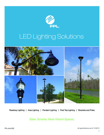
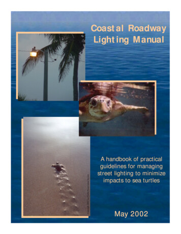
Figure 1 presents a flow chart that shows the design process, including the design of the powerdistribution system. Quality control steps are identified.Initial StudyStudy the project including the roadways, the interchanges, etc. and identify the followingfeatures: Names of the different segments of the project, including streets, ramps, bridges,overpasses, tunnels, etc.Identify diverging lanes, converging lanes, abrupt curves, accelerating, and deceleratingtraffic lanes. These locations will need careful attention.Identify segments of the project where the road is categorized as major, collector, and localstreets. It is important that you determine the pedestrian crossings locations.Identify structures, walls, fences, ditches, water ponds, lakes, or rivers.Identify pedestrian walkways, sidewalks and bikeways. They require different lightingcriteria.Identify any hospitals, residential areas, airports, observatories, industrial, commercialzones or any other critical locations close by.Identify public rights of way.Identify the elevations of the different roads, ramps, overpass, etc. on the project. This isespecially important whether you intend to use high mast fixtures for lighting roads atdifferent elevations (See the Case Study), or if you use offset lighting.Determine the width of the different pavements, shoulders, medians, barriers, etc.Visit the project site to get a feeling for the area. Is the project an extension of an existingarea with existing patterns and/or existing types of fixtures that need to be matched?Identify parts where you can use the median for lighting. This might be a good ideaprovided that it does not cause problems for traffic during maintenance.Identify the clear zones where you intend to locate poles. Try to locate the poles behindguardrails, girders, and ditches whenever you can, you might consider fixtures that allowsfor large setbacks.Are there any trees near by? Which kind? How large can they grow? It is important thatyou know this information; you might consider moving some of the poles, to avoidobscuring the lights, or cutting the trees.Talk to the transportation engineers and ask for their comments, ideas, or concerns.Listen to the customer’s requirements and identify their interests and concerns.Establish the lighting criterion for each segment of the projects. Different roadclassifications have different criterion, so do not treat them the same. We have combinedthe road way lighting criteria in one table (See Table 1).Identify the appropriate Pavement Classification (R1, R2, R3, or R4).2
Figure 1Lighting Design Flow Chart.3
calLocalLocal0.4FreewayClass BExpressway0.6RoadAverageLuminanceL(avg)Cd/m 2FreewayClass g/LminRatioRatioMax.Lmax/Lmin Lvmax/LavgallowedMax allowed Max. ntained MaintainedAverageAverageAverageIlluminance Illuminance Illuminanceon Pavement on Pavement on PavementR1 in fcR2&R3 in fcR4 in fcTable 1Roadway Lighting Design Criteria 0.40.5STV Criteria LavgCd/mWeighting 2 MedianAverage VL 7.3 m0.30.30.40.40.40.50.60.70.80.40.30.4LavgCd/m 2Median 7.3 m
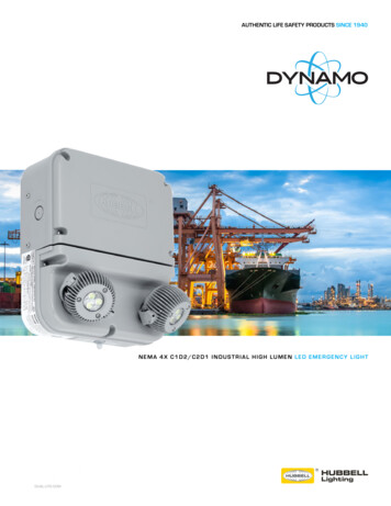
Beside the RP-8-00 you may find useful information in other publications such as the AASHTOinformal guide for roadway lighting, and publications from your state department oftransportationSelecting Fixtures and Poles“THE GOAL IS AN OPTIMUM FIXTURE ON AN OPTIMUM POLE”Although there are hundreds of fixtures available in the market, you can simplify and optimizethe selection process, by selecting only fixtures that are designed for roadway application. Theperformance characteristics of each fixture and lamp are unique. The characteristics may beobtained from the manufacturer graphically or as an electronic file.Roadway fixtures are classified, Figure 2, as non-cutoff, semi-cutoff, cutoff, and full-cutoff,based on the amount of light permitted above the horizontal. A full cutoff fixture permits nolight at or above the horizontal, which minimizes lighting pollution such as Urban Sky glow.CANDELA 5% OFRATED LUMEN90 DEGREES90 DEGREES80 DEGREES80 DEGREESNO INTENSITYLIMITSCANDELA 20%OF RATED LUMENNON-CUTOFFSEMI-CUTOFFCANDELA 2.5%OF RATED LUMEN90 DEGREESNO LIGHT AT ORABOVE 90 DEGREES80 DEGREES80 DEGREESCANDELA 10%OF RATED LUMENCANDELA 10%OF RATED LUMENCUTOFFFULL-CUTOFFFigure 2Roadway Fixture Cutoff ClassificationMany jurisdictions are moving towards limiting fixtures used on roadways to cutoff or fullcutoff. From the designer’s perspective it just produces a better design if you adopt that as astandard.5
Select the fixtures to be of cutoff-type or full cutoff with zero tilt, and zero roll angles tominimize glare, and urban sky glow. When luminaries are tilted, or rolled upward, they can emitlight above the horizontal.Fixtures for roadway applications are further classified as Short, Medium, and Long. Thisclassification essentially relates the type of fixture, the spacing, and the mounting height: Short - the maximum luminaire spacing is generally less than 4.5 times the mountingheight. Medium - the maximum luminaire spacing is generally less than 7.5 times the mountingheight. Long - the maximum luminaire spacing is generally less than 12 times the mountingheight.The IESNA Lighting Handbook Reference & Applications presents a more exact definition ofvertical light distributions.Fixtures for roadway applications are classified as type I, II, III, or IV (Figure 3). Notice therelationships between different fixtures types and width of the road. Type I fixtures are generallyused for narrow roadways. Type IV is used for wide, multi-lane roads.Figure 3Roadway Fixture Type Classification6
Now that we understand the roads and have selected the fixtures, we can select the mountingpoles. Although we have taken several steps in the design process, we will have to confirm thecorrectness of our selections later.The primary selection of the poles will depend on several factors, such as width of the road, andthe location of the project: As a rule of thumb use shorter poles for narrower roads, taller poles for wider roads. Useshort poles close to residential areas.Select poles designed for roadway applications.For safety, and unless poles are behind walls, guard rails, or ditches, select poles of breakaway design, even if the poles will be located well off the road.Select the poles to withstand the wind force in the project area.Pole foundation and/or mounting design must be considered carefully and coordinated inthe overall design of the roadway, bridges, etc.Select poles aesthetically appealing, and suitable for the project, especially in down town,and historical areas.Consider high power factor fixtures and ballasts.The mounting height of a fixture is very important. It can affect the results of the designconsiderably. The horizontal illumination is inversely proportional to the square of the verticaldistance, as measured from the light source. In general the relationship is expressed as;E ( I cos3 θ ) / h2Where:“ The Cosine Cubed Law”E illuminanceI source intensityH vertical distance from the sourceθ the angle as measured from the vertical to the incident ray.ØdhcEFigure 4The Cosine Cubed Law7
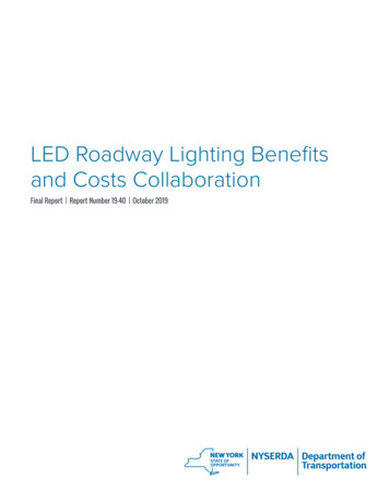
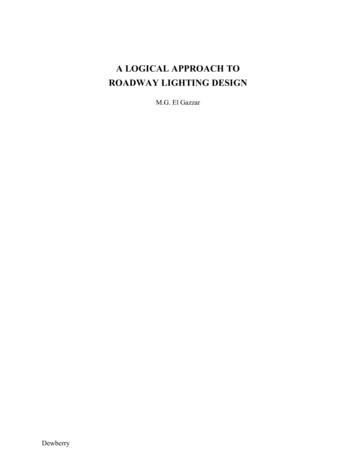
Notice that there can be a difference between the height of a pole and the mounting-height of thefixture. If a 35-foot-high pole is placed on a 4-foot-high wall, the mounting height is 39 foot.As with everything, there are tradeoffs to be made in lighting design. Pole height impacts thefixture spacing. Shorter poles, a relative term, are less costly and typically use lower wattagelamps than higher poles, but more fixtures are needed to obtain the required uniformity.Also notice that when you illuminate roads at different elevations from one fixture (or groups offixtures) you should expect different levels of illumination at the different road surfaces. Fromthe Cubed Cosine Law above, and considering the simplified case where θ 0, we can say thatthe illuminance at two different elevations E1 and E2, if illuminated from the same source, can becalculated from:E1/E2 h22/h12If, for example, h1 is 50 feet and h2 is 20 feet, then the E1/E2 (20)2/(50)2 0.16. This means thatthe illuminance at the lower roadway is only 16 percent of the upper roadway. This isparticularly important when high mast fixtures are used to illuminate roadways or ramps atdifferent elevations. A ramp is continuously changing elevation, so the lighting at the lower partof the ramp could be very different from the lighting on the upper part of the ramp, if the lightingis from the same source.Again, the fixture manufacturers give you guidance on the appropriate fixture to use for variousmounting heights.Case StudyAt an interchange, a secondary road passes 25 feet above a multi-lane divided highway. A longcurved ramp climbs from the highway level to a height of 50 feet and then descends down to thesecondary road level.A conceptual design of the interchange was prepared using high mast fixtures mounted on 100foot-high poles. However, a 3D rendering of the interchange produced both very bright andcompletely dark areas on the ramp. Three problems were identified:1.2.3.The level of illuminance was significantly different from one road to another.The level of illuminance was significantly different throughout the climb and ascent ofthe ramp.The higher roadway caused shadows on the lower roadway.Figure 5 shows the 3D rendering of the ramp.Figure 6 shows a plan and an elevation. On the plan you will find the statistical zones, point-bypoint illuminance levels, in footcandles (fc), on the ramp, on the secondary roadway, and on themain roadway. The dashed lines relate the statistical zones on the plan to the ramp, and theroadways in the elevations. Also, the source of light at the top of the high mast in the elevationis connected to the projection of the 0.2-footcandle templates in the elevation.The iso-footcandle template of 0.2 fc appears as a perfect circle on the plan and indicatesilluminance levels of higher than 0.2 fc inside the circle; however we have to remember twobasics pieces of information:8
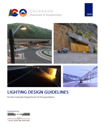
1.The iso-footcandle template shows the performance on the road surface of the mainroadway (elevation of 0 foot).2.The light from the high mast fixture forms a cone of light not a cylinder.So, at higher elevations, although the ramp appeared within the iso-footcandle template in theplan view, parts of the ramp are outside of the light cone in the elevation view.The solution to the problem was to move the high mast away from the ramp, and to use 35-foothigh poles with 150 watts full-cutoff fixtures to illuminate the ramp. The main roadway and thesecondary roadways were lit using high masts with various distributions of fixtures and locatedsuch that the lighting criteria was achieved on each roadway. Illuminance was calculatedconsidering the slope of the ramp to verify that the lighting design criteria were also met for theramp.Table 2 summarizes the results of the calculations.Figure 5-ARendering (The Problem)– Case Study9
Figure 5-BRendering (The Solution)– Case Study10
Figure 6Plan and Elevation – Case Study11
Table 2Calculations - Case StudyCriteriaZone 2Zone 3Zone 4Zone 5Zone 6Zone 7Zone 8Zone 9UnitsAvgMaxMinAvg/MinMax/MinLuminanceCd/sq 0.00Veiling LuminanceCd/sq m0.000.030.000.000.00LuminanceCd/sq 1.00Veiling LuminanceCd/sq m0.020.060.000.000.00LuminanceCd/sq ng LuminanceCd/sq m0.000.000.000.000.00LuminanceCd/sq 13.00Veiling LuminanceCd/sq m0.000.000.000.000.00LuminanceCd/sq 13.00Veiling LuminanceCd/sq m0.070.160.023.508.00LuminanceCd/sq m0.300.60Illuminancefc0.731.300.107.3013.00Veiling LuminanceCd/sq m0.000.040.000.000.00LuminanceCd/sq 72.33Veiling LuminanceCd/sq m0.000.030.000.000.00LuminanceCd/sq 4013.00Cd/sq m0.030.170.000.000.00Veiling Luminance12
Locating the Fixtures and the PolesModern lighting design software will allow you to import the CAD files of the roadway. TheCAD files typically contain more information than you need. For simplicity (and fasterprocessing), activate only the layers you need for your work such as the edge of pavement,shoulder of the road, stationing, structures, curbs, sidewalks, etc. Eliminate the layers you don’tneed. You can combine the layers into one layer. Pay attention to the scales used in the files(hopefully they are at full scale) and the units.The photometric characteristics of a fixture are available as an electronic file that presents theresults of tests conducted by the manufacturers. A common type of file is the IES file. Usually atest number identifies the IES file. These test results are based on testing of a fixture with aspecific lamp. Results may differ greatly if, say, a 400-watt lamp is replaced with a 250-wattlamp, even if the fixture is available with the smaller lamp. Performance is not necessarilyscalable.Most probably the software will allow you to select the fixture by selecting the IES file.Iso-footcandle templates are an easy way to locate the fixtures (Remember you have alreadycalculated the spacing during modeling of the sample areas of the roadway, use the spacing as aninitial guidance for locating the fixtures). This method is not much different from what was donemanually before software became available, but software makes it easier. There are many waysto use templates, but I have found out that, if you use a template with the minimum requiredilluminance for the road or a template with the average required illuminance, you will be able tobetter manipulate the location of the fixtures.Play with the templates to get an idea of the influence of various design parameters on thelighting performance. Locate a few fixtures at a suitable distance from the edge of the pavement,or over the roadway if you are using arms. Place templates using various degrees of overlap andperform the pertinent lighting calculations.In selecting the poles locations, make sure that you stay out of the clear zone of the roadway,behind manmade or natural deflectors. Install the poles behind the shoulder of the road. Stayaway from signs and traffic signal lights. Also consider the hazard of servicing the poles. If youdecided to put poles in the median make sure that the median is large enough to install the poles,and the shoulders are large enough to accommodate a maintenance truck.Verifying the Lighting Design CriteriaMost designers now use commercially available software to model the lighting design, to locatethe fixtures and perform lighting calculations. Point-by-point calculations produced using thesoftware permits a level of design and analysis that was, until recently, not practical.There are usually three criteria considered in roadway lighting: Luminance, Illuminance, andSmall Target visibility. Luminance, in Candela/meter2 (Cd/sq m) is a measure of how bright the roadway is, takinginto consideration the amount of light reflected from the pavement.Illuminance, in Lux, is a measure of the amount of light incident on the roadway.(In the United States footcandle is usually used as the unit for illuminance)13
Small target visibility is affected by factors such as the luminance of the target, theluminance of the immediate background, the adaptation level of the adjacentsurroundings, and the disability glare. Small target visibility is a weighted average.These criteria are typically computed for a discrete area (zone) of interest. Of more interest thatspecific values are the minimum, maximum, and average values within the zone and the ratios ofaverage-to-minimum and maximum-to-minimum. The calculated values should be within therecommended design criterion.As a rule-of-thumb, you can increase the average illuminance level by locating the fixtures closertogether. In other words, the average illuminance will increase as the iso-footcandle templatesoverlap more. Alternately, you can use higher wattage lamps (higher Lumens) - you have tocheck first with the manufacturers to verify that you can do that.Often you can meet the required average level of illumination but the minimum level of lightingis well below the requirement. You have to look at the area you selected to conduct thecalculations. Select an area that traces the edge of the pavement, and covered with templates.Notice that the average-to-minimum illumination ratio is important, and if the minimumillumination is low, then the average to minimum illumination ratio will be high. You can takeone of these measures in order to increase the minimum, and improve the average to minimumratio: add another fixture, aim or reorient a fixture or several fixtures toward the point ofminimum illumination level.Sometimes an area receives more light than the rest of the calculations zone. This might happendue to a concentration of fixtures or due to spillover from fixtures outside of the calculationzone. Make sure that you identify the point or points of maximum illumination, and try toeliminate the reason for this level of higher illumination. You might relocate, remove, orreorient fixtures.Table B1 of the RP-8-00 shows valuable relationships between the different factors.LIGHTING POLLUTIONAn important issue that the roadway lighting designer must be concerned with is lightingpollution caused by glare, light trespass and “urban sky glow”. Lighting pollution has become asignificant political issue. It has been found that 35-to-50 percent of lighting pollution in theU.S. is caused by roadway lighting. This means that the solution to a significant part of theproblem is in the hands of the lighting designer.GlareThere are several types of glare; the one that we are most concerned with is disability glare glare that causes reduced visual performance. Disability glare, or “veiling luminance” as we willrefer to it, reduces the ability of the driver to distinguish objects clearly.The veiling luminance, Lv, can be calculated as:Lv Σ 10 Evi / (θ2 1.5 θ )14
Where:Lv:Ev:θ:N:Veiling Luminance, at the observer location, in Candela/meter2.Vertical illuminance, on the plane of the observer’s eye.Angle between the line of sight and luminaries, in degrees.Number of luminaries in sight.Notice that θ depends on the fixture mounting height and other factors like the width of the road,the height of the observer’s eyes, and the observer’s location. Also notice that there is acontribution in the value of the glare due to the other fixtures that the observer can see.This simply means that we can reduce the value of the Veiling Luminance by decreasing thevertical illuminance and increasing the angle θ. This can be achieved by:1.2.3.Selecting luminaries of low vertical illuminance. (Remember we still have to meet thecriteria)Increase the mounting height.Increase the spacing between poles.Something to consider is that increasing the mounting height may result in a considerable priceincrease to the project. Increasing fixtures spacing will generally result in a less costly design.Light TrespassBe aware that when you illuminate a roadway you are also illuminating the area around the pole.Light may fall in places where it is not wanted such as residential areas, annoying people andpossibly depriving them of sleep. It might interfere with the performance of security cameras.An acceptable level of light trespass is typically 0.01-footcandle, which is equivalent to moonlight. An easy way to find the limit of trespass is to utilize a fixture template that has an isofootcandle of 0.01. When you have plotted the fixture locations draw a tangent to the 0.01 isofootcandle, this line will define the limit of the light trespass.Avoid using high masts fixtures close to residential areas, hospitals and hotels, and Airportsunless FAA approval is obtained.Urban Sky GlowIt is the right of our children and future generations to look up and see the stars. Lighting above90 degrees participates in the urban sky glow. Use cut off luminaries and luminaries with shieldsaround them to help solve the problem.ConfusionThe worst thing any designer would like to have happen is that a driver could be confused due tothe roadway lighting. Make sure that intersections, converging traffic points, diverging trafficpoints, ramps and islands are well lit. Notice that at intersections, points of diverging andconverging traffic, ramps, etc., the width of the roadway, as well as the geometry change. Usepoles with 2, 3, or 4 fixtures. Also reduce the spacing to provide these critical areas with goodlighting.A roadway parallel to or close to an airport runway can create a disaster. Avoid this situation,and use shields on the fixtures to control light spill and patterns of poles locations that differfrom the ones on a runway.15
A tired driver can take the wrong exit, miss it all together, or get into an accident due to beingconfused by lighting patterns. Avoid this situation, know where the signs are, and make sure thatthey are well seen. Consider the lighting patterns at the exits, the entrances, the channeledroadways and the medians. Ensure they are well lit and that the patterns will not causeconfusion.OTHER IMPORTANT ISSUESEnergy ConsumptionAnother factor the designer has to be concerned with is the energy consumption. Although theenergy consumption price does not appear on the bill of material, it is a cost that the customerwill have to pay (as a matter of fact, the whole community has to pay). Select high efficiencyluminaries, ballasts and transformers. Consider low level lighting using 100 Watt, and 150 Wattlamps on narrower roads and ramps, and higher level lighting using 400 Watt, and high masts onlarger roads. Calculate the energy consumption for the design. Consider alternate designstrategies that could lower energy consumption.AestheticsUse your common sense in selecting the fixtures and the poles. If the project is an extension of aroadway try to match the fixtures and the poles. Use attractive fixtures and poles in residentialarea, without sacrificing the photometric performance or the maintenance criteria. Selectappropriate fixtures and poles in historical or down town areas. Lighting can influence people –hopefully for the better.Tunnel LightingLighting a tunnel at night is not much different than lighting an open roadway; however, lightingthe tunnel during the day is a problem that deserves good attention. The tunnel itself is a hazard.It can appear during the day as a black hole that prompt the driver to suddenly slow down, whichcould be a factor in causing an accident.The problem is also a problem of adaptability. Human eyes can adapt easiest moving fromhigher levels of illumination to lower levels of illumination. The transition from daylight (about10,000 foot-candles) into darkness can blind the driver momentarily. It is recommended thatvery high lighting levels (1000-1,500 footcandle dropping down to 800 footcandles) at theentrance of the tunnel and for a short distance of about 10 percent of the length of the tunnel.The illumination level should then be decreased to about 50 footcandle for about another 20percent of the length of the tunnel. This scheme is reversed on the other side of the tunnel. Thecentral portion of the tunnel (about 40 percent of the tunnel length) can be lit from 20 footcandleto 5 footcandle.The daylight illumination will change from one day to another, season to season. You mightconsider an automated system that will vary the illuminance level, based on the intensity of thedaylight. Consider an intermediate light level for dawn and dusk.Select watertight luminaries using low pressure sodium lamps with features such as ease ofmaintenance and installation. Also consider fixtures with thin profiles to minimize the risks dueto small clearances.16
Underbridge LightingYou can think of the area under a bridge as a short tunnel; however the problem of adaptation isnot as severe. We recommend continuously lighting the underbridge area. Also use non-cutoff,high pressure sodium fixtures. The non-cutoff fixtures will light the underside of the deck,reducing the cavern effect.CONCLUSION:Roadway lighting design is a responsibility that should be taken seriously – the safety of thepublic is impacted by design decisions. A designer should apply a logical and systematicapproach, asking questions such as “What is the basis for selecting this fixture?”, “What is thebasis for using this spacing?”, “Why will I use this mounting height?”. In other words, thedesigner should move from the realm of art only to the realm of science and common sense. Adesigner should always remember that the ultimate purpose of Roadway Lighting Design issafety.17
replace a good text in road way lighting design, or the designer's research and practice for arriving into an optimum design. This advisory is basically an attempt to focus the designer's . Short - the maximum luminaire spacing is generally less than 4.5 times the mounting height. Medium - the maximum luminaire spacing is .