Transcription
SAP2000 , ETABS , SAFE and Revit 2018Data Exchange DocumentationISO XRV080317M1 Rev. 0Proudly developed in the United States of AmericaVersion 2018.0August 2017
CopyrightCopyright Computers and Structures, Inc., 2017All rights reserved.The CSI Logo , ETABS , SAP2000 , SAFE are registered trademarks of Computers andStructures, Inc. Watch & LearnTM is a trademark of Computers and Structures, Inc. Revit is aregistered trademark of Autodesk.The computer program ETABS, SAP2000, and SAFE and all associated documentation areproprietary and copyrighted products. Worldwide rights of ownership rest with Computers andStructures, Inc. Unlicensed use of the program or reproduction of the documentation in anyform, without prior written authorization from Computers and Structures, Inc., is explicitlyprohibited.No part of this publication may be reproduced or distributed in any form or by any means, orstored in a database or retrieval system, without the prior explicit written permission of thepublisher.Further information and copies of this documentation may be obtained from:Computers and Structures, Inc.www.csiamerica.cominfo@csiamerica.com (for general information)support@csiamerica.com (for technical support)2
DISCLAIMERCONSIDERABLE TIME, EFFORT AND EXPENSE HAVE GONE INTO THE DEVELOPMENT AND TESTING OFTHIS SOFTWARE. HOWEVER, THE USER ACCEPTS AND UNDERSTANDS THAT NO WARRANTY IS EXPRESSEDOR IMPLIED BY THE DEVELOPERS OR THE DISTRIBUTORS ON THE ACCURACY OR THE RELIABILITY OF THISPRODUCT.THIS PRODUCT IS A PRACTICAL AND POWERFUL TOOL FOR STRUCTURAL DESIGN. HOWEVER, THE USERMUST EXPLICITLY UNDERSTAND THE BASIC ASSUMPTIONS OF THE SOFTWARE MODELING, ANALYSIS,AND DESIGN ALGORITHMS AND COMPENSATE FOR THE ASPECTS THAT ARE NOT ADDRESSED.THE INFORMATION PRODUCED BY THE SOFTWARE MUST BE CHECKED BY A QUALIFIED ANDEXPERIENCED ENGINEER. THE ENGINEER MUST INDEPENDENTLY VERIFY THE RESULTS AND TAKEPROFESSIONAL RESPONSIBILITY FOR THE INFORMATION THAT IS USED.3
IntroductionThis document describes how to exchange Building Information Modeling (BIM) data betweenRevit 2018 and ETABS 2015 or later, SAP2000 v17 or greater, and SAFE 2014 or later.This document includes three sections. The first section reviews data exchange between Revitand ETABS. The second section reviews data exchange between Revit and SAP2000. The thirdsection reviews data exchange between Revit and SAFE.Data exchange between Revit and ETABS supports four different workflows:1) Exporting from Revit to create a new ETABS model.2) Exporting from Revit to update an existing ETABS model.3) Importing from ETABS to create a new Revit project.4) Importing from ETABS to update an existing Revit project. In this case, you maychoose to update locations, designs, or both.Data exchange between Revit and SAP2000 supports two different workflows:1) Exporting from Revit to create a new SAP2000 model.2) Exporting from Revit to update an existing SAP2000 model. SAP2000 v17.2.0 orlater is required.3) Importing from SAP2000 to create a new Revit project.4) Importing from SAP2000 to update an existing Revit project. In this case, you maychoose to update locations, designs, or both. SAP2000 v17.2.0 or later is required.Data exchange between Revit and SAFE supports four different workflows:1) Exporting from Revit to create a new SAFE model.2) Exporting from Revit to update an existing SAFE model.3) Importing from SAFE to create a new Revit project.4) Importing from SAFE to update an existing Revit project. In this case, you maychoose to only update locations, only update designs, or update both.4
The flow of information is represented in the schematic below:Export from Revit to create a new ETABS, SAP2000 or SAFE model.Export from Revit to update an existing ETABS or SAFE model.ETABS , SAP2000 or SAFE Revit StructureImport from ETABS, SAP2000 or SAFE to create a new Revitproject.Import from ETABS, SAP2000 or SAFE to update an existingRevit project.5
Revit and ETABS Data ExchangeData exchange between CSiXRevit and ETABS supports four different workflows:1) Exporting from Revit to create a new ETABS model.2) Exporting from Revit to update an existing ETABS model.3) Importing from ETABS to create a new Revit project.4) Importing from ETABS to update an existing Revit project.Supported WorkflowsExporting from Revit to create a new ETABS modelThe table below provides an overview of the data imported in ETABS when exporting from Revitto create a new ETABS model:ActionCreation of Project ElementSupportedGrid LinesStory LevelsMaterialsStructural Columns andStructural FramingNotesTransfers geometry, offsets, end releases, andbeam and brace alignment points into ETABS.Imports columns based on splice informationin ETABS.Steel Column andFraming Family TypesCreates and maps equivalent ETABS framesections. Makes Auto-Select Lists in ETABS forall families used in the Revit project.Creates and maps equivalent ETABS framesections.Slanted or warped walls not imported.Creates and maps equivalent ETABS wallsections.Concrete Column andFraming Family TypesWallsWall Family TypesWall OpeningsFloorsSloped floors with more than four outercorners are projected on a horizontal plane.Creates and maps equivalent ETABS slab anddeck sections.Floor Family TypesFloor Openings6
FootingsCreates fixed joint restraints in ETABSwherever a footing occurs in Revit.Point LoadsLine LoadsArea LoadsLoad CasesNon-uniform area loads not imported.Creates both an ETABS load pattern and loadcase for each Revit load case.Load CombosGridsThe following Grid attributes are created in ETABS: Grid Name: The same grid name is used in the ETABS grid bubble. Grid Points: The start and end points are used to define the general grid line in ETABS. Curved Grid: The center point, radius, start angle and aperture are used to define thecircular grid line in ETABS.MaterialsThe following material attributes are created in ETABS: Material Name: The same name is used in ETABS. Material Type: The Revit material type is used to identify the ETABS material type,namely Concrete, Steel or Other. Young’s Modulus: The Young’s modulus values from Revit set the ETABS materialYoung’s modulus (E). These three values (for the three different directions) cannot bezero in ETABS. If the first value is zero, then the default ETABS value is used. If any of theremaining two are zero, then the first non-zero value is used. For an isotropic material,the first value is used for all other directions. Poisson’s Ratio: Poisson’s Ratio values from Revit set the ETABS material Poisson’s Ratio(u). These three values (for the three different directions) cannot be zero in ETABS. If thefirst value is zero, then the default ETABS value is used. If any of the remaining two arezero, then the first non-zero value is used. For an isotropic material, the first value isused for all other directions. Shear Modulus: Shear Modulus value from Revit set the ETABS material Shear Modulus(G). If the Revit material is defined as isotropic, then ETABS calculates this value on thebasis of the Young’s Modulus and the Poisson’s Ratio. In the case of an orthotropicmaterial, these three values (for the three different directions) cannot be zero in ETABS.If the first value is zero, then the default ETABS value is used. If any of the remaining twoare zero, then the first non-zero value is used. Thermal Expansion Coefficient: The thermal expansion coefficient from Revit sets theETABS material thermal expansion coefficient (Alpha). These three values (for the three7
different directions) cannot be zero in ETABS. If the first value is zero, then the defaultETABS value is used. If any of the remaining two values are zero, then the first non-zerovalue is used. For an isotropic material, the first value is used for all other directions.Weight Density and Mass Density: The unit weight value from Revit sets the ETABSmaterial weight density (w) and mass density (m). In ETABS, the mass density iscalculated by dividing the weight density by the gravitational constant (g). The weightdensity cannot be zero in ETABS. If the unit weight is zero in Revit, then the defaultETABS densities are used.Damping Ratio: This value is not in used in the current version of ETABS.Bending Reinforcement: The bending reinforcement value from Revit sets the ETABSmaterial main reinforcement Fy if the type is concrete. If this value is zero in Revit, thenthe default ETABS value is used.Shear Reinforcement: The shear reinforcement value from Revit sets the ETABS materialshear reinforcement Fy if the type is concrete. If this value is zero in Revit, then thedefault ETABS value is used.Resistance Calculation Strength: The resistance calculation strength from Revit sets theETABS material f’c factor. If this value is zero in Revit, then the default ETABS value isused.Behavior: The Revit behavior tag is used to identify the isotropic or orthotropic materialsin ETABS.Concrete Compression: The concrete compression value from Revit sets the ETABSmaterial f’c if the type is concrete.Lightweight: The Revit lightweight tag is used to identify the lightweight concretematerial in ETABS.Shear Strength Reduction: This value is not in used in the current version of ETABS.Yield Stress: The yield stress value from Revit sets the ETABS material yielding stress Fy ifthe type is steel. If this value is zero in Revit, then the default ETABS value is used.Tensile Strength: The tensile stress value from Revit sets the ETABS material ultimatestress Fu if the type is steel. If this value is zero in Revit, then the default ETABS value isused.Steel Reduction Factor: This value is not in used in the current version of ETABS.Only those materials linked with floors, walls, or frames in the Revit project are importedinto ETABS.ETABS writes a warning in the .wrn file it writes when a default value is used while importingmaterials from the Revit project.8
Structural Columns and FramingThe following Revit column and framing element attributes are imported into ETABS: Frame Curves: Straight framing elements are imported as straight ETABS frame objects.Curved framing elements that are not arc shaped are imported as series of short ETABSobjects based on the lines defining their analytical models. Arc shaped framing elementsare imported as arc shaped ETABS line objects. Frame End Points and Curves: For straight column and framing elements and curvedframing elements other than arc shaped, the coordinates of the end points of the linesdefining the analytical model of the element are retrieved and ETABS joint objects withidentical coordinates are created. When the analytical model of an element includesrigid links, the ETABS joint objects are created at the ends of the rigid links with ETABSjoints offsets created to model the link. For arc shaped framing elements, thecoordinates of the end points of the elements themselves are imported instead of theend points of their analytical models because these analytical models consist of series ofshort straight segments and such a tessellation is not required in ETABS 2013 and later.Columns are imported with the Local Axis 1 always pointing up, and beams and braceswith their Local Axis 1 always in the first quadrant, which means that the end joints mayhave been switched compared to the Revit end points. Multi-story columns and bracesare automatically broken into several single story ETABS frame objects. This is requiredfor reporting and design. Frame Sections: The family type assigned to the Revit element is imported along with thewhole family. ETABS converts the Revit family to an ETABS auto selection list. End Releases: End releases defined in the element analytical models are imported intoETABS. ETABS restricts releases that would cause an analytical instability, such as forexample torsion released at both ends. When that happens, ETABS writes a warning inthe .wrn file it writes. When ETABS joints have been switched compared to Revit endpoints, end releases are also switched. Insertion Points: In Revit, the beam or brace insertion point is defined by the followingtwo parameters:o Z-Direction Justificationo Lateral JustificationETABS calculates the corresponding insertion point on the basis of these two parameters.If these parameters are not defined then the default alignment, Top Center, is chosen.Columns in Revit have no parameters corresponding to the ETABS insertion point andthey are imported with a Middle Center insertion point. End Offsets: When the analytical model of an element includes rigid links, these areimported as end offsets. You can visualize them by looking at the model in extruded view.In addition, when a beam has its z-Direction Justification parameter set to Other, anadditional vertical offset is created at both ends of the ETABS frame object based on thevalue of the z-Direction Offset parameter. Other beam offset parameters such as Start9
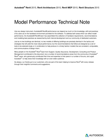
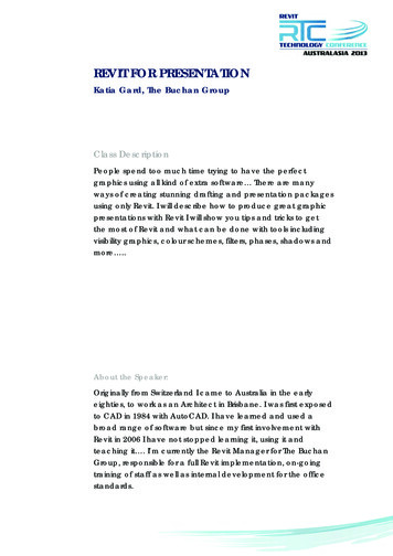
Level Offset and End Level Offset are not taken into consideration because, except for arcshaped members, end joints are located based on the end points of the analytical modelwhich already reflects the values of these parameters. When ETABS joints have beenswitched compared to Revit end points, end offsets are also switched.Orientation Angles: The ETABS Local Axis 2 Angle of columns is computed based on theirrotation as internally stored in Revit. The ETABS Local Axis 2 Angle of beams and braces iscomputed based on the value of their Cross-Section Rotation parameter. When ETABSjoints have been switched compared to Revit end points, rotations are adjustedaccordingly.Frame SectionsThe mapping of Revit frame section attributes depends upon their type.ETABS first tries to find the name of the section in its database. Most steel sections can bemapped automatically. If a section is not found in the database, ETABS tries to create thesesections parametrically.ETABS maps sections through the following steps:1) ETABS first tries to map Revit family sections to the currently loaded ETABS database bycomparing section names. If it finds a match then that section is mapped. All geometriccross sectional properties are used from the ETABS section. Blank spaces are alwaysremoved and upper/lower cases dissimilarities are ignored when comparing names.2) Next, ETABS tries to map Revit family sections to a section in the ETABS section propertyfiles (.XML) by comparing section names. If ETABS finds a section with a matching name,then that section is used along with all its geometric cross sectional properties. In theabsence of an exact name match, ETABS looks for a close match where the Revit namecontains the ETABS name. The user is given the option to add/remove or change thesearch order of the property files during the import into ETABS from the Revit project. InFigure 1, “UC356x406x287” section is loaded from “BSShapes.XML”.10
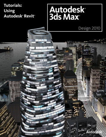
Figure 1: Import of sections from section property files (.XML files)Figure 2: Adding /Removing XML files when importing into ETABS3) If a Revit family section cannot be mapped to an ETABS section from any of the propertyfiles, then ETABS checks if it is a Revit parametric section. If it is a parametric section,ETABS creates an equivalent section and names it after the Revit family section.4) If a Revit family section is not parametrically defined, then a new ETABS section namedafter the Revit family section is created with default ETABS section properties. The userhas the option to add a new parametric section as a replacement section or to load a11
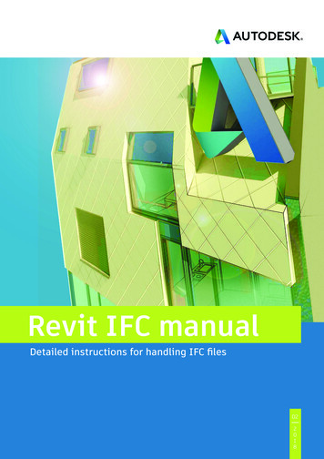
new section from any other section property file(.XML) that is not in the properties file(.XML) list.5) The user has the option to save a mapping file which can then be reused on subsequentimports. A sample mapping file is shown in Figure 3.Figure 3: Section mapping file6) Some European family names do not map with the ETABS sections in Europeanproperties file (.XML) due to prefix/suffix incompatibility. For Revit families with“Universal Columns” or “Universal Beams” categories, ETABS changes the suffix to prefixwhen importing.12
The parameters list is given for concrete and wood structural families in the following table.Member TypeCONCRETECOLUMNSCONCRETEFRAMINGFamily CAST-DOUBLE TEEPRECAST-INVERTED TEEPRECAST-L SHAPED BEAMCONCRETE-RECTANGULARBEAM, PRECASTRECTANGULAR BEAMPRECAST-SINGLE TEEWOODCOLUMNSWOODFRAMINGSTEELFRAMINGDIMENSION LUMBERCOLUMNGLULAM-SOUTHERN PINECOLUMNGLULAM-WESTERN SPECIESCOLUMNPSL-PARALLEL STRANDLUMBER-COLUMNTIMBER-COLUMNDIMENSION LUMBERGLULAM-SOUTHERN PINEGLULAM-WESTERN SPECIESLVL-LAMINATED VENEERLUMBERTIMBEROPEN WEB JOISTPLYWOOD WEB JOISTPLATEROUND BARTable 1: Parameters used in ETABS13ParametersB, HBBB, H CHAMFERWIDTH, TEE WIDTH,STEM WIDTH, SLABDEPTH, DEPTHH1, H, B, SEATH1, H, B, SEATB, HWIDTH, STEMWIDTH, SLAB DEPTH,DEPTHB, D, SY, SX, IY, IX, AB, D, SY, SX, IY, IX, AB, D, SY, SX, IY, IX, AB, D, SY, SX, IY, IX, AB, D, SY, SX, IY, IX, AB, D, SY, SX, IY, IX, AB, D, SY, SX, IY, IX, AB, D, SY, SX, IY, IX, AB, D, SY, SX, IY, IX, AB, D, SY, SX, IY, IX, AB, HB, HB, DD
In-place family membersRevit in-place family members are not imported into ETABS.WallsThe following wall attributes are imported into ETABS: Points: The coordinate of all points defined in the wall analytical model are retrieved andETABS joint objects with identical coordinates are created. Revit walls may be defined ashaving more than four corners, but ETABS walls can only have three or four nodes. Revitwalls with more than four outer corners are broken into several four node walls, with afew three node walls when some of the edges are sloped. Also, multi-story walls arebroken into several single story ETABS walls. This is required for reporting and concretereinforcement design. Wall Curve: Arc shaped curved walls with horizontal bases and tops are imported asETABS curved walls. Straight wall edges are imported as such. Other edges aretessellated, with the degree of approximation defined internally by Revit, and the wall isimported as a series of walls. Note that when a Revit wall is arc shaped in plane but itstop is not horizontal, its top curve is not an arc and will be tessellated. Wall Openings: Wall openings are imported based on their locations. Opening with morethan four corners are broken into three and four node openings. Multi-story openingsare broken into several single story openings. Wall Thickness: A Revit wall has different layers, each having different thickness andmaterial properties. ETABS only considers the layer with the maximum thickness whenimporting the data from Revit. Wall Materials: All the materials assigned to the different layers of a Revit wall areimported into ETABS. However, only one material is assigned to the ETABS wall sectionproperty. Users have the option in ETABS to change the material, if necessary. Thematerial of the wall layer with the maximum thickness is used.Slanted or warped walls, with their top not lined up with the base when looked at fromabove, are not imported.FloorsThe following floor attributes are imported into ETABS: Floor Points: The coordinate of all points defined in the floor analytical model areretrieved and ETABS joint objects with identical coordinates are created. Floor Curves: Floor edges that are arc shaped are imported as arcs in ETABS. Straightfloor edges are imported as such. All other curved floor edges are tessellated, with thedegree of approximation defined internally by Revit. Floors with more than four outercorners are projected onto a horizontal plane at an elevation matching their averageelevation.14
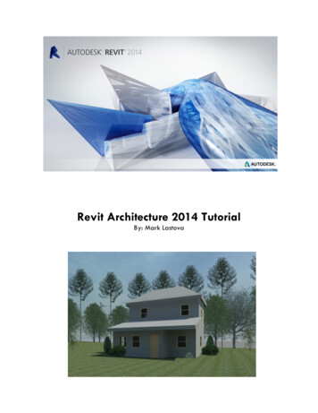
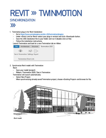
Number of Layers: In Revit, different layers may be defined within a floor. ETABS readsthe floor layer information and treats the floor as a deck if more than one layer ispresent in the floor. Otherwise the floor is treated as a slab.Layer Thickness: ETABS imports the thickness of each layer. If the floor is a deck, itssection property is defined by the maximum thickness of the layers.Below is an example of how Revit Deck parameters are mapped to ETABS Deck Sectionparameters:Revit Deck Family15
16
ETABS Deck SectionIn this example, there are two layers in the Revit Deck section:1) Concrete – Cast-in-Place (Thickness 5”)2) Metal – Deck (Thickness 0 )Layer 2 stands for a deck profile with the following properties: HRWRRRSRTHICKNESS17
Here is the procedure CSiXRevit uses to fill ETABS deck section properties: The layer with the maximum thickness is selected and treated it as the overallthickness of the section. This layer is used to define the material of the ETABSdeck section. Slab Depth tc overall thickness of section – HR Deck Depth hr HR Rib Width Top wrt WR Rib Width Bottom wrb RR Rib Spacing Sr SR Composite Deck Studs diameter RR Composite Deck Stud height (hs) overall thickness of section - THICKNESS Layer Materials: ETABS imports the material of each layer. The material of the thickestlayer is assigned to the Slab or Deck section. A default material is used if no material isdefined in Revit. Users may later change the material of the different layers as requiredin ETABS.Floor Span Directions: The Revit span direction is imported for decks. A default directionis used if no span direction is defined in Revit.Floor Openings (Regular or Irregular): Openings defined in Revit by“Modeling Opening Vertical Opening” are imported into ETABS. All curves in suchopenings are converted into a number of smaller segments, which gives the suitablecurvature for the area boundary.Ramps: All inclined slabs with four nodes are imported as ramp objects in ETABS.OpeningsThe following openings are imported into ETABS from Revit: Horizontal Openings: These are imported as openings in the floors. Wall Openings: These are imported as openings in the walls (vertical planes). For details,please check Openings in Walls. Shaft Openings: These are imported as openings in the floors (horizontal planes). Fordetails, please check Shaft Openings.18
ShaftsIn Revit, a shaft opening element is defined as a 3D shaft having upper and lower limits (oroffset elevations from upper and lower story levels). In ETABS the shaft is imported ashorizontal floor openings at all the story levels that lie between the upper and lower limits ofthe 3D shaft.FootingsThe following footing properties are imported into ETABS from Revit: Points: All the points defining the shape of the footing are imported. In ETABS allcolumns that are located in this area are restrained. Width, Length and Thickness: For rectangular footings, the width, length and thicknessare imported. In this case, ETABS locates all the columns within the rectangular footingarea and restrains them.Note: Only rectangular footings are processed.Point LoadsThe following point load attributes are imported into ETABS from Revit: Load Case Name: It sets the corresponding load case name in ETABS. Location: It is used to define the point of application of the load. Fx, Fy, Fz, Mx, My, Mz: All forces and moments applied in the global direction, in Revit,are transferred in a similar manner into ETABS.Line LoadsThe following line load attributes are imported into ETABS from Revit: Load Case Name: It sets the corresponding load case name in ETABS. Start and End Point Locations: Used to define the start and end point of the line load.Line loads carrying the gravitational load and overlapping more than one beam aredistributed to the corresponding beams in ETABS. In the case of a lateral line load, usersmust check no line load overlaps more than one beam; otherwise it is not processed inthe ETABS analysis. Fx, Fy, Fz, Mx, My, Mz: All forces and moments applied in the global direction, in Revit,are transferred in a similar manner into ETABS. A Revit line load which includes morethan one of these components is imported as several ETABS line loads because ETABSline loads are mono-directional.19
Area LoadsThe following area load attributes are imported into ETABS from Revit: Load Case Name: It sets the corresponding load case name in ETABS. Points: Points are used to define the geometry of the loading area. Curved edges that arearc shaped are imported as arcs. Straight edges are imported as such. Other edges aretessellated, with the degree of approximation defined internally by Revit. LoadX, LoadY, and LoadZ: All loads applied in the global direction in Revit are transferredin a similar manner into ETABS.Non-uniform surface loads are not supported in ETABS and not imported.Load CasesThe following load case attributes are imported into ETABS from Revit: Load Case Name: The same name is used for the ETABS load case. Load Case Category: It is used to define the load case type in ETABS. The mapping isshown in the following table:Revit Load CaseCategoryDeadLiveWindSnowRoof LiveAccidentalTemperatureSeismicETABS Load Case TypeDeadLiveWindSnowLiveOtherOtherQuakeLoad CombosThe following load combination attributes are imported into ETABS from Revit: Load Combination Name: The same name is used for the ETABS Load CombinationName. Load Cases: The same load cases list is used in ETABS to define the Load Combination. Load Case Factor: The same load case factors are used for the corresponding load casesin the ETABS load combination.ETABS Auto Select ListsETABS automatically creates Auto-select lists based on Revit family types that are loaded inthe current Revit project and being exported into ETABS.20
Exporting from Revit to update an existing ETABS modelThe table below provides an overview of the data imported in ETABS when exporting from Revitto update an existing ETABS model:ActionCreation of Model ElementSupportedGridsStory LevelsMaterialsFramesNotesCreates equivalent ETABS materials.Transfers geometry, offsets, end releases, andbeam and brace alignment points, into ETABS.Cuts all columns at story levels.Frame SectionsSteel SectionsConcrete SectionsWallsWall PropertiesMaps to ETABS database sections.Creates and maps equivalent ETABS sections.Wall OpeningsFloorsSlabs PropertiesDeck PropertiesFloor OpeningsFootingsCreates fixed joint restraints in ETABS wherever afooting occurs in Revit.Joint LoadsFrame LoadsShell LoadsLoad CasesLoad CombosUpdate of GridsStory LevelsMaterialsFramesFrame SectionsXXX21
Steel SectionsConcrete SectionsWallsWall PropertiesWall OpeningsDeletion of XXWalls with changing number of sides arereplaced.XXFloorsSlabs PropertiesDeck PropertiesFloor OpeningsXXXPoint LoadsLine LoadsArea LoadsLoad CasesLoad CombosXXXXWall openings with changing number of sides arereplaced.Floor openings with changing number of sidesare replaced.GridsStory LevelsFramesWallsWall OpeningsFloorsFloor OpeningsFootingsPoint LoadsLine LoadsArea LoadsLoad CasesLoad CombosIMPORTANT NOTE: Deletion of objects when updating a model only works if you are sendingthe ENTIRE model. If the “selection only” update feature is used, deletion of items is notsupported.22
Importing from ETABS to create a new Revit ProjectThe table below provides an overview of the data imported in Revit when creating a new Revitproject:ActionCreation of Model ElementSupportedGridsStory LevelsMaterialsNotesImports Concrete and Steel materials into Revitfrom ETABS. Limitation is the Revit projectshould have one default concrete and onedefault steel material for duplication, otherwisethe material will be created in Revit but itsparameters will not be updated, and theproperties of the new materials are identical tothose of the template materials.Imports steel columns based on splice locationsin ETABS.Column alignment points are not exported toRevit because the concept is not supported inRevit.FramesFrame SectionsSteel SectionsConcrete SectionsCreates and maps equivalent Revit sections.See mapping below.Slanted walls not imported.WallsWall PropertiesWall OpeningsFloorsSlabs PropertiesDeck PropertiesFootingsLoad CasesJoint LoadsFrame object LoadsCreates equivalent Revit point line loads andtrapezoidal line loads.Creates equivalent Revit area loads.Shell Member LoadsLoad Combos23
Mapping of ETABS section types to Revit t re-Column.rfaConcrete-Round-Column.rfaBeams and BracesETABSRectangularLTSteel PlateSteel RodRevit FamilyConcrete-Rectangular Beam.rfaPrecast-L Shaped Beam.rfaPrecast-Single Tee.rfaPlate.rfaRound Bar.rfa24
Importing from ETABS to Update an Existing Revit ProjectThe table below provides an overview of the data imported in Revit when updating an existingRevit project:ActionCreation of Model ElementSupportedGridsStory LevelsMaterialsFramesFrame SectionsSteel SectionsConcrete SectionsNotesCreates and maps equivalent Revit sections.See mapping at end of previous section.WallsWall PropertiesWall OpeningsFloorsSlabs PropertiesDeck PropertiesFloor OpeningsFootingsLoad CasesJoint LoadsLine LoadsArea LoadsLoad CombosUpdate of GridsStory LevelsMaterialsFramesUpdates changes to column locations only forcolumns not meshed in ETABS and with a 1:1correspondence between Revit and ETABS. Youcan choose between leaving columns meshed inETABS in their original Revit locations or replacingthem with the ETABS meshed columns.Frame SectionsSteel Sections25
Concrete SectionsUpdates Beam, Column and Brace sectionassignments; however section parametersthemselves do not update. If you would like tobring in the changes to the parameters fromETABS, create a new section with the desiredparameters in ETABS and assign the new sectionto the frame.Updates changes in wall location only for wallsnot meshed in ETABS and with a 1:1correspondence between Revit and ETABS. Youcan choose between leaving walls meshed inETABS in their original Revit locations or replacingthem with the ETABS meshed walls.Updates wall type assignments; however walltypes themselves do not update. If a w
If the Revit material is defined as isotropic, then ETABS calculates this value on the basis of the Young’s Modulus and the Poisson’s Ratio. In the case of an orthotropic material, these three values (for