Transcription
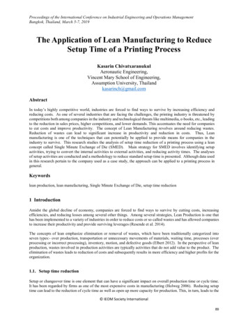
SOLUTIONS FOR LEANMANUFACTURINGwww.pronic.com Secondarytappingoperation,welded orcrimped nut Costly Not lean Quality issues LEAN Light Cost effectiveSuccess depends on yourstrategical choices.Your worldwide tapping partner
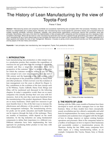
www.pronic.comTAPPING SOLUTIONS FOR: Progressive diesTransfer pressesFine blanking diesMulti-slide pressesStand alone machinesYour worldwide tapping partner
ur worldwide tapping partner
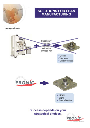
ELECTRIC / ELECTRONICwww.pronic.comHOUSEHOLD APPLIANCESYour worldwide tapping partner
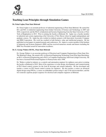
MOUNTINGCONFIGURATIONSMOBILE SUPPORT MOUNTINGTools with material lift.www.pronic.com Best press speed / tap life balance.Maintain standard stripper travel.Tapping unit follows the strip.Thread the part as soon as material feeds into position.Top Dead CenterBottom Dead CenterTapping from top tobottomTapping from bottomto topTapping horizontallyYour worldwide tapping partner
SOLID MOUNTINGTools with no strip lift (or under 1 mm). Basic mounting. Requires a simplified tapping unit.Top Dead CenterBottom Dead Centerwww.pronic.comSTRIPPER MOUNTINGComplex tools with no possibility for mobilesupport or solid mounting. Run the die with different press strokes with no modification of the tapping unit. Suit transfer presses. Requires a simplified tapping unit. Requires a transmission schock absorber. Tap operates during stripper stroke.Top Dead CenterBottom Dead CenterOTHER MOUNTINGS20 other configurations possible, please contact us.Your worldwide tapping partner
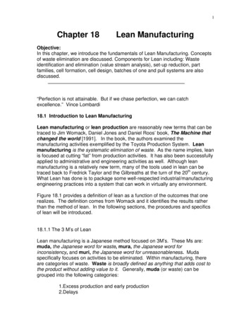
IN-DIE DESIGNCONSIDERATIONS ** Mobile support examplewww.pronic.comTapping unitmain housingLead screwTop Dead CenterBottom Dead CenterDrive nutPARAMETERSG Distance between tapping unit lower face (REF) andtop face of the material (or top of extrusion).Z Tapping unit drive nut height.W Lead screw’s position in regard of the drive nut (at TopDead Center, the lead screw must be engaged in the nut).PRONIC will provide you with W mini and W maxi.S Drive nut position in regard of the unit main housing. Thedrive nut must be engaged in the main housing.PRONIC will provide you with the S mini and S maxi.Y Lubrication tube (reservoir) length. For tapping unit leadscrew lubrication.X Distance between the tip of the tap and the tapping unitlower face (REF).To start your application, tap position has to be set upwhen the press is at Top Dead Center.Extrusion downExtrusion upGear ratio Tap travel for 1 mm press stroke.Your worldwide tapping partner
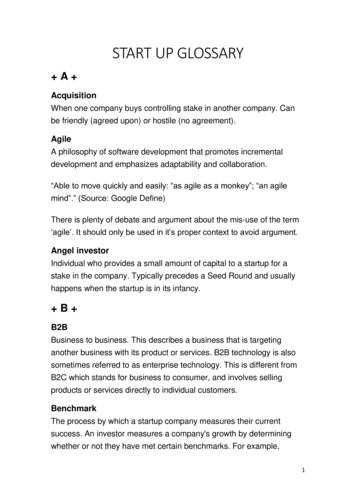
DESIGN PROCEDURE ** Mobile support example1. Position the device above or underneath the material at recommendedG distance (value provided by PRONIC).www.pronic.com2. Position the drive nut in the advised range: S Max - S Min.3. Position the lead screw in the advised range: W Max - W Min.KINEMATICSStrip feedingangle 270 90 Untappingoperationarea180 TappingoperationareaOnly for example :TOTAL PRESS STROKE - A250 mmFEEDING ANGLE - 60 STRIP LIFT - D30 mmSTRIPPER TRAVEL - C16 mmAPPLICATION:DEPTH TO TAP:UNIT MODEL:GEAR RATIO:1 x M10 x 1,5010 mmM1D0,0672Recommended speedDIST. DEVICE / STRIP - G10 mmMOBILE SUPPORT TRAVEL - D30 mm28 SPMu agdxyTOP DEAD CENTER00,0010,0030,007,71-2,29END OF FEEDING3016,7510,0030,008,84-1,16STRIPPER CONTACT129204,0010,0030,0021,4111,41STRIP DOWN - DIE LEVEL150234,0010,000,0023,4313,43BOTTOM DEAD CENTER180250,0010,000,0024,5014,50TAP FLUSH WITH MATERIAL4334,0810,0030,0010,000,00Your worldwide tapping partner
M1B - M1D TAPPING UNITSThe most popular single tap unit Flexibility. Different press strokes and tap diameterswww.pronic.compossible. Wide range of mounting configurations. Compact design. Simple installation. Reliability. Cartridge system that equals same pitchas the tap assures quality threads. Low maintenance level. No pressure on the part necessaryfor the tapping operation.M1B Security. Misfeed protection that prevents tapbreakage. Seals protecting from polluting particles. ServiceM1D. CAD files available (2D and 3D). Free checking of your tool design.Quick installationkitDrive screwShear pin for outof range torqueQuick release lub. line(option)All items protectedagainst pollutionGear box (easy changeof application or pressstroke)Quick releaseclamp for lockingunit into the toolQuick installationkitDrive nutStandard roll forming tap(quick release system)Mounted with radial andaxial complianceTap microlubricationnozzle (option)Lubrication tube forthe drive screwOptions:. Shock absorber for stripper mounting configuration. Stroke reducer for very short press strokes. Simplified transmission for lower shoe or stripper mounting. Built on tap microlubrication nozzles. Horizontal tapping extension.Your worldwide tapping partner
DIMENSIONS(Specifications can change without notice - Please contact us)M1BM1Dwww.pronic.comSPECIFICATIONSModelTapping rangePress stroke - maximumStrip lift value with mobile supportconfigurationM1BM1DM2,5 - M6M2,5 - M20300 mm (12’’)600 mm (24’’)0 to 80 mm(or more upon request)MOUNTINGS EXAMPLES. Solid mounting. Mobile support mounting. Stripper mounting. Tapping from top to bottom. Tapping from bottom to top. Horizontal tapping.SchockabsorberStripper mounting withshock absorberMobile support mountingHorizontal tappingYour worldwide tapping partner
MxB - MxD TAPPING UNITSTotal adaptability with removable headswww.pronic.com Flexibility. Different press strokes and tap diameters possible. Wide range of mounting configurations. ReliabilityMxB-2B. Cartridge system that equals same pitch asthe tap assures quality threads. Low maintenance level. Security. Misfeed protection prevents tap breackage. Seals protecting from polluting particles. Service. Free checking of your tool drawings. CAD files available (2D - 3D). Productivity. For changing the taps, there’s no need.to remove the transmission. Cost savingMxD2-6D. The transmission can be re-used forother applications (with other tappingheads) buying a complete new unit isnot necessary. Require less tool space than multiplesingle tap units solutions.TransmissionRemovable headYour worldwide tapping partner
DIMENSIONS(Specifications can change without notice - Please contact us)MxD TranmissionMxB Transmissionwww.pronic.comMulti-cartridge heads will be designed depending on your specs.SPECIFICATIONSMulti-cartridge headModelModelBDM2,5 - M6M2,5 - M2037,5 mm (Underthis value,contact us)48 mm (Underthis value,contact us)Tapping rangeMinimum centerdistance betweentapsTransmissionMOUNTINGS EXAMPLES. Solid mounting. Mobile support mounting. Stripper mounting. Tapping from top to bottom. Tapping from bottom to top. Horizontal tapping.Stripper mountingwith shock absorberPress strokemaximumStrip liftvalueMxBMxD300 mm(12’’)600 mm(24’’)0 to 80 mmMobile supportmountingMxD2-4DYour worldwide tapping partner
BxB - B xB AND CxDTAPPING UNITSThe prefered tapping units for smalltap center-distances or small taps.www.pronic.com Reliability. The tap is controlled by its own system. Low maintenance level. AdaptabilityBS 2B. Tapping from different diameters possiblewith close center-distances. Compact design. Security. Safety system for missing hole. Seals protecting from polluting particles. Service. Free checking of your tool drawings. CAD files available (2D - 3D).C4DDrive screwQuick installationkitQuick releaseclamp for lockingunit into the toolDrive nutStandard roll forming tap(quick release system)Tap holder with radial andaxial play / Spring loadedLubrication tube forthe drive screwOptions:. Shock absorber for stripper mounting configuration. Stroke reducer for very short press strokes. Simplified transmission for lower shoe or stripper mounting. Built onto tap microlubrication nozzleYour worldwide tapping partner
DIMENSIONS(Specifications can change without noticePlease contact us)BxBwww.pronic.comB xBCxDSPECIFICATIONSModelTapping rangeMin / Max center-distance *Strip lift value with mobile support mountingBxBB xBCxDM0,6 to M5M0.6 to M8M0,6 to M1010 - 2510 - 4510 - 550 to 80 mm* Depends on tap sizeMOUNTINGS EXAMPLES. Solid mountingMobile supportmounting. Mobile support mounting. Stripper mounting. Tapping from top to bottom. Tapping from bottom to topStripper mounting withshock absorberYour worldwide tapping partner
Tapping unit main housing PARAMETERS G Distance between tapping unit lower face (REF) and top face of the material (or top of extrusion). Z Tapping unit drive nut height. W Lead screw’s position in regard of the drive nut (at Top Dead Center, the lead screw must be engaged in