Transcription
Session 7Rebar modeling in Revit: Can You Model AllReinforcement?Håvard Vasshaug, Darkhvasshaug@gmail.comClass DescriptionThis course will explain the advanced Revit reinforcement tools you needto master to be able to deliver detailed, complete and accuratereinforcement design for construction. We will look at how to deal with themost common concrete elements as well as specialized structures such ascurved walls and post tensioned slabs, utilizing everything from DetailComponents, Standard Rebar and Adaptive Components.About the SpeakerHåvard Vasshaug is a structural engineer, Revit power user and DigitalDesign Manager at Dark, one of Norway's largest planning, architectureand interior design practices. He has vast experience providing Revittraining, solutions and seminars for architects and engineers at AutodeskAuthorized Training Centers the past 8 years, and now uses thisbackground to share knowledge of Revit solutions at Dark and towhoever else that enjoys it.He is a part of the Autodesk BIM Open Source Project SteeringCommittee, and a member of the program committee of, and presenterat The Smart Drawing Conference. He also presented at AutodeskUniversity 2012 and Revit Technology Conference North America 2013.Håvard is an enthusiastic blogger and national Revit forum administrator.Collaborating with Autodesk, he is a member of the IFC Nordic CustomerCouncil, a dedicated Revit Beta contributor, a member of the BuildingParticipatory Design Pane, and a very, very proud Revit Gunslinger.
Rebar Modeling in RevitHåvard Vasshaug, DarkIntroductionWhen I first started working as a structural engineer back in 2003, I wasintroduced to the concepts of reinforcement drawings and bendingschedules for the first time. This was of course something we never saw atthe university, where static, dynamic and finite element analysis coveredthe curriculum. Little was I to know that these drawings and scheduleswere to be my main occupation the first years. And now, looking back,not always did I feel like Michelangelo drawing away.Today, most of my fellow engineers and I are modeling almost allreinforcement in our projects in 3D. Some structures are harder to master,but most are quite easy. We are planning for our skills and knowledge toappend a future where all fabrication detailing is done in a 3D database,and what better 3D database than Revit?Our two biggest challenges in doing this are efficiently modelingreinforcement in non-rectangular, curved and double-curved concreteforms, and the shouting valley of a gap between new BIM and old CAD.The first problem is something I will discuss shortly.The last problem is one we share with our software vendors. They are givenan impossible task by us; “Please make the most sophisticated modelingsoftware in the history of humankind, and make it how I want it in 5 years.At the same time, make it compatible with 50 year old symbolic drawingstandards.” How do you solve a problem like that? As I said, and inparticular this is true for reinforcement, we are faced with the samechallenge when we need to model all reinforcement in a 3D buildinginformation model, and simultaneously represent and communicate it inthe same way as we did 20 years ago. It is the ever present gap betweenfuture and past. In the end we are dealing with humans. And manyhumans love the past.The future, however, is way more exciting. The future is a place whereeverything that is to be built is represented in an intuitive 3D model, justthe way it is going to be built. The future is a place where the materialsordered and delivered on site, is done so from the same high-detail 3Dmodel. The future is a world where engineers and contractorsPage 2 of 102
Rebar Modeling in RevitHåvard Vasshaug, Darkcommunicate design using the most intuitive way possible yet; the visual3-dimensional representation of future.Then, perhaps, we can feel more like Michelangelo.NoteAll information in this class handout is based on Revit 2014, Build20130308 1515(x64) and the 2014 Open Source IFC Exporter v3.3.2 (UIv.2.3.0).If any of my examples deviate from your experience, please run a checkon the versions you are using.Page 3 of 102
Rebar Modeling in RevitHåvard Vasshaug, DarkTable of ContentsTable of Contents . 4Modeling challenges; what is difficult? . 6Complex concrete forms . 6The gap between BIM and CAD. 7Why use Revit in the first place? . 10Reinforcement categories and parameters . 11Rebar Cover . 12Structural Rebar . 13Structural Area Reinforcement . 32Structural Path Reinforcement . 37Structural Fabric Areas . 39Structural Fabric Reinforcement. 40Complex Reinforcement Modeling . 44Post Tension Tendons . 45Schedules . 56Parameters. 57Filters. 59Lap Splices and Total Lengths . 60Working Schedules . 65Totals . 65Wire Fabric Reinforcement Schedules . 67Drawings . 70Sections . 71Plans and Elevations . 73Page 4 of 102
Rebar Modeling in RevitHåvard Vasshaug, DarkView Templates . 77Filters. 783D Views . 78Model Export . 85Autodesk Design Review and DWF. 85Industry Foundation Classes (IFC) . 90Navisworks . 95Inventor Publisher . 97Going Forward . 101Page 5 of 102
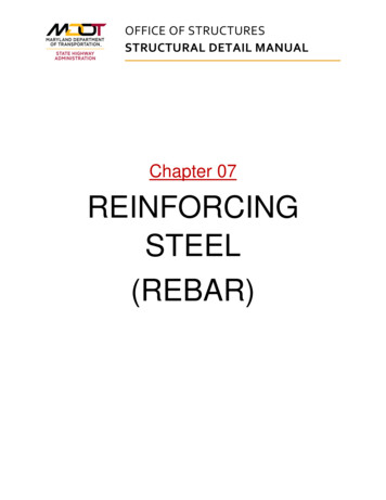
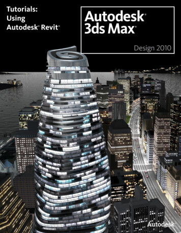
Rebar Modeling in RevitHåvard Vasshaug, DarkModeling challenges; what is difficult?As I described in the introduction, two things are perceived as challengingwhen working with 3D reinforcement in Revit; Complex concrete formsand the gap between BIM and CAD.Complex concrete formsThe way the different reinforcement tools appear today, we mustacknowledge that some forms are inefficient to do 3D in Revit, and someseem straight out impossible.This is mostly due to the confession that a single distribution of StructuralRebars cannot have varying dimensions, and cannot be distributed inanother direction and form than linear and perpendicular to the rebarshape plane. These limitations turn the workflow inefficient and boring, butnot impossible.Figure 1: Curved, tapered concrete beamWhen concrete walls and slabs end up curved or double-curved, theavailable reinforcement tools simply do not pull through. In some casesPage 6 of 102
Rebar Modeling in RevitHåvard Vasshaug, Darkthe tools does not even recognize the concrete element. These limitationsturn the workflow impossible.Figure 2: Double-curved concrete wall by faceThat said, there is always a way to cheat. In theexample above (yes Revit, it is a wall) youcould do the Detail Item, Annotation Symboland Note Block tricks, and land reinforcementdrawings and schedules without modeling asingle 3D element. You could also look intoAdaptive Components for an alternative wayFigure 3: Are you sure?of modeling 3D reinforcement.The gap between BIM and CADI tried to explain the problem of the gap between BIM and CAD to afriend the other day, and for a structural engineer there are few thingsthat illustrate this better than reinforcement drawings. Think about thesymbols on reinforcement drawings as hieroglyphs from ancient Egypt. Atone time in history, they were needed. How better document somethingwhen all you have is rock and hammer?Page 7 of 102
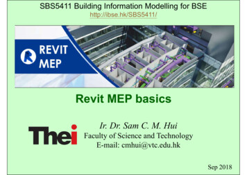
Rebar Modeling in RevitHåvard Vasshaug, DarkSome years back in time from today all we had were lines and text on acomputer. Some years before that we (well, really more ‘they’ to behonest) had paper and pencil. Should they draw every single reinforcingbar in all projects? Of course not. That would be the mother of allboredom, and suicide rates would shoot through the roofs throughout theengineering businesses. They needed symbolic representation. Enterhieroglyphs.Figure 4: Ancient Egyptian hieroglyphs, stolen from The InternetNow, the contractor who reads these drawings today has maybe 30years’ experience studying hieroglyphs. He knows them like he knows hisback of his hand, and you can be sure he knows when you’ve missed aline. All his younger colleagues, on the other hand, and especially all ouryounger engineers who are now modeling all that 3D reinforcement in thefirst place, does not get a word ancient Egyptian. These guys wonder whythey have to learn the ancient language when everyone except thecontractor with 30 years in the business is speaking plain 3D.Page 8 of 102
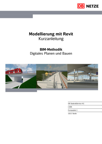
Rebar Modeling in RevitHåvard Vasshaug, DarkFigure 5: Top modern reinforcement drawingEverybody on the planet understands 3D. Even the contractor with 30years on site understands 3D. He just does not master the tools.Hence, we’re challenged with not only modeling 3-dimensionalreinforcement in complex forms, but also representing it in ancient waysfor people to understand. It does not help either that these hieroglyphsvary between countries. So, we basically have one variation ofhieroglyphs for each country. We’ve got Norwegian hieroglyphs andSwedish hieroglyphs. It’s a mess.And in all this, we ask of Autodesk to enhance 3D modeling functionalityand 2D representation tools at the same time. And as of now, theavailable 2D tools do not support efficient drawing production. I’ll get intothe details later.These two challenges need to be considered by each company andindividual, with each different project in mind before a plan for using 3Dreinforcement tools in Revit is introduced.Page 9 of 102
Rebar Modeling in RevitHåvard Vasshaug, DarkWhy use Revit in the first place?It is possible to track down building information modeling software thatdoes 3D reinforcement better than Revit. Tekla Structures is possibly one ofthem. The cross-disciplinary environment in Revit however, often results inthe fact that we have native concrete elements available from early on.And unless you have a very sophisticated modeling transfer applicationavailable between the programs, and you’re stuck with maintaining twobuilding information models – one for cross-disciplinary coordination andone for structural detailing, you’re in a world of pain. Multiply that with theopen BIM exchange format IFC, and your original world of pain nowseems like The Bahamas.So, when you have decided to go all in and put your life in the hands ofthe Revit Reinforcement Tools, you probably want to get a view at whatyou’ve got to deal with.Page 10 of 102
Rebar Modeling in RevitHåvard Vasshaug, DarkReinforcement categories and parametersIn Revit you can model regular reinforcement and wire fabricreinforcement. There are a number of various categories assigned forthese reinforcement types, and they all behave and interconnectdifferently; Structural Rebar Structural Area Reinforcement Structural Path Reinforcement Structural Fabric Areas Structural Fabric ReinforcementIn addition, Structural Rebars are defined from two system families andone regular family, and Structural Fabric Reinforcement of two systemfamilies; Structural Rebaro Rebar Bar (System)o Rebar Hook (System)o Rebar Shape (Regular) Structural Area Reinforcement Structural Path Reinforcement Structural Fabric Areas Structural Fabric Reinforcemento Fabric Sheet (System)o Fabric Wire (System)Before we hit the actual rebar tools we should have a short look at animportant setting for all our reinforcement; The Rebar Cover Settings.Page 11 of 102
Rebar Modeling in RevitHåvard Vasshaug, DarkRebar CoverThe first thing yo
the Revit Reinforcement Tools, you probably want to get a view at what you’ve got to deal with. Rebar Modeling in Revit Håvard Vasshaug, Dark Page 11 of 102 Reinforcement categories and parameters In Revit you can model regular reinforcement and wire fabric reinforcement. There are a number of various categories assigned for these reinforcement types, and they all behave and