Transcription
Applications of Geometric Tolerancingto Machine DesignSecond EditionFaryar 1EtesamiPortland State University
Design for FitApplications of Geometric Tolerancing to Machine DesignSecond EditionFaryar EtesamiMechanical and Materials Engineering DepartmentPortland State University
ISBN 978-0-9914638-0-0Copyright 2016 by Faryar EtesamiAll rights reserved. No part of this book may be reproduced or transmitted electronicallyor otherwise without permission in writing from the publisher.The information presented in this book and any associated software is included foreducational purposes only. The author and publisher make no warrantees of any kindwith regard to applicability or validity of the materials presented in this book.Send Correspondence to: Design4Fit@gmail.com
PrefaceThis book is written for students enrolled in an undergraduate program in mechanicalengineering (BSME) or similar programs. The material presented is based on my notesfor teaching mechanical tolerancing for nearly thirty years. The book’s emphasis is on fitand alignment requirements for machine components. Fit assurance makes up themajority of challenging applications in tolerancing. Design for specific functions is easyby comparison. For design engineers, knowing how to apply geometric tolerances hasbeen a challenge even for engineers who have practiced geometric tolerancing for a longtime. The syntax and meaning of geometric tolerancing statements can be learned easilyand quickly but knowing how to use them correctly is much more difficult. For years Itaught the geometric tolerancing standards in great detail as one may teach a foreignlanguage using a dictionary. That method of training was fine for those on inspection ormanufacturing career paths but was not very useful to design engineers. Finally, Idecided to teach the subject not as a geometric tolerancing class but as a design-for-fitclass. I found this new method to be far more effective and useful to design engineersthan covering every detail of the GDT standard.The objective of this book is to present the subject of design-for-fit in a format that issuitable as a college-level course. I believe students learn in the context of simpleexamples free of distractions. They are then able to apply what they learned in morecomplex applications. For that reason, I have done my best to convey the concepts ofdesign for fit in the context of simple examples. Graduating mechanical engineers whodesign and document parts and assemblies should have a basic understanding of thedesign-for-fit principles presented in Chapters 1-9. The book can be used to supporta junior-level or senior-level class in a BSME program or it can make a companiontextbook for capstone design classes. Interested students or practitioners can follow upwith the more advanced topics in Chapter-10 and Chapter-11 on multipart fits and fitanalysis. Since this book does not cover every detail of the geometric tolerancingstandard I recommend having a copy of the standard document as an official and legalreference. Low-cost pdf versions of the GDT standard can be found online.Faryar EtesamiJanuary 2016
CONTENTSChapter-1Dimensions and Tolerances . 51.1.Overview . 51.2.Evolution of tolerancing . 61.3.Geometric versus dimensional tolerances . 101.4.Importance of clear geometry communication practices . 151.5.Functional feature vocabulary . 161.6.Preferred practices in dimensioning . 201.7.Figures of accuracy for dimensions and tolerances . 38Chapter-2A Design Engineer’s Overview ofTolerance Statements - Part-I . 442.1.Overview . 442.2.Interpretation of geometric tolerances . 442.3.Dimensional tolerances . 462.4.Geometric tolerances . 472.5.Tolerances of form . 502.6.Flatness . 502.7.Meaning of m symbol next to the tolerance value . 532.8.Straightness . 552.9.Circularity . 562.10.Cylindricity . 582.11.Tolerances of orientation . 592.12.Parallelism . 612.13.Identifying the axis of an imperfect cylinder . 622.14.Perpendicularity . 672.15.Angularity . 701
Chapter-3A Design Engineer’s Overview ofTolerance Statements - Part-II . 773.1.Overview . 773.2.Tolerances of location . 773.3.Position tolerance . 773.4.Meaning of mmodifier applied to datum features . 913.5.Composite position tolerance – multiple segments . 933.6.Composite position tolerance – single segment . 963.7.Runout tolerances . 983.8.Profile tolerances . 1073.9.Profile tolerances in place of tolerances . 112Chapter-4Default Tolerances .1284.1.Overview . 1284.2.Default tolerancing methods . 1284.3.Datum targets . 1334.4.Default tolerancing and small features . 1374.5.Default tolerances for fillets and rounds. 1384.6.A different way of dealing with small features . 139Chapter-5Tolerance Design for Unconstrained Fits Between Two PartsPart-I .1505.1.Overview . 1505.2.Unconstrained fits versus constrained fits . 1505.3.Fit assurance between two parts . 1545.4.Theoretical gages for tolerance statements that use the m symbol . 1605.5.Fit formula . 1615.6.Default form control implied by limits of size . 1645.7.Use of zero geometric tolerance at MMC . 1655.8.Fit formula when using zero geometric tolerancing at MMC . 1675.9.Defining a fit boundary without the m modifier . 1675.10.A note on the use of modifiers . 1682
5.11.Unconstrained fits and Rule#1 . 1695.12.Unconstrained interference fits . 171Chapter-6Tolerance Design for Unconstrained Fits Between Two PartsPart-II .1766.1.Overview . 1766.2.An overview of the limits and fits standard (ANSI B4.2) . 1786.3.Preferred sizes . 1806.4.Offsets letters (fundamental deviations indicator letters) . 1816.5.International tolerance grades . 1836.6.Preferred fits . 1836.7.Dependency of offsets and tolerance grades on basic size . 1946.8.Tolerance design examples in precision fit applications . 194Chapter-7Tolerance Design for Orientation-constrained FitsBetween Two Parts .2087.1.Overview . 2087.2.The fit boundary and the theoretical gage . 2107.3.A word on inspection . 2167.4.MMC boundary as fit boundary . 2177.5.Situations where MMC modified tolerances cannot be used . 2197.6.Datum feature flatness . 2207.7.Is it necessary to specify axis straightness? . 2257.8.Defining a fit boundary without the m modifier . 227Chapter-8Tolerance Design for Location-constrained FitsBetween Two Parts .2308.1.Overview . 2308.2.The fit boundary and the theoretical gage . 2318.3.Datum priority . 2368.4.Datum frame precision . 2418.5.Imperfect geometry relationships are not intuitive . 2433
8.6.Fit of feature patterns . 2458.7.Simultaneous fit of different features . 2488.8.Additional alignment fit features . 2528.9.Situations where the use of m is not possible or recommended . 2558.10.Defining a fit boundary without the mmodifier . 256Chapter-9Assemblies with Threaded Fasteners.2679.1.Overview . 2679.2.Fits using threaded studs or screws . 2679.3.Fits using threaded press-fit studs . 2699.4.Assembly with cap screws and threaded holes . 2719.5.Assembly of two plates with loose bolts and nuts . 2729.6.Fastener applications - Example-1. 2749.7.Fastener applications - Example-2. 2779.8.Fastener applications - Example-3. 2799.9.Fastener applications - Example-4. 2829.10.Tolerance design of press-fit inserts . 287Chapter-10Tolerance Design of Multipart Fits .29510.1.Overview . 29510.2.Application of profile tolerances . 29610.3.Fits involving features-of-size . 301Chapter-11Tolerance Analysis of Multipart Fits .33811.1.Overview . 33811.2.Tolerance analysis overview . 33811.3.Examples . 3394
Chapter-1Dimensions and Tolerances1.1. OverviewThis chapter presents an introduction to tolerancing practice and suggests guidelines forclear graphics communication. After a part’s exact geometry is defined in a CAD systema design engineer must also specify the part’s geometric tolerances. Tolerances defineallowable deviations of part features from their theoretical definitions. Sincemanufacturing variations are inevitable, tolerancing information allows productionpersonnel to select suitable processes and methods to meet part precision requirements atminimum cost.Tolerancing specifications include tolerance types and tolerance values. For example, if asurface is to be flat with high precision, then the designer applies a standard flatnesstolerance symbol and specifies a tolerance value. The smaller the tolerance value, themore flat the surface would be manufactured, but usually at a higher cost. The geometrictolerancing standard to which the material in this book refers to is the ASME Y14.5-2009standard, which from now on, will be referred to as the GDT standard. The GDT standardprovides a variety of symbols a designer can use to control various geometric aspects of apart.The design engineer’s challenge is to create a set of precision specifications that is justenough to assure proper fit and function of a part in an assembly. The ability to createwell-toleranced parts is an important skill for a mechanical design engineer. Improperuse of tolerance types or tolerance values can affect the cost of production as well as thefit and function of assemblies. To be safe, many designers resort to over-specification oftolerances. Tolerance types that are not needed or tolerance values that call forunnecessary precision would lead to higher production costs and delays in a variety ofways such as: The need for more expensive processes or machines The need for additional or more time-consuming processing steps Lack of in-house capability The need for more expensive tooling A reduction in throughput The need for more expensive inspection tools An increase in rework and reject rates Excessive lead-timesOn the other hand, lack of necessary tolerance types or tolerance values that do not callfor enough precision reduce the cost of production at the risk of non-assembly orfunctional compromises. Some of the more common failures associated with lack ofsufficient geometric precision are: Risk of parts not fitting properly into an assembly5
Improper performance Improper sealing Loss of operation accuracy Loss of power Loss of functionally critical alignments Improper thermal or electrical conductionStructural Failures Improper load distribution Unexpected dynamic loads Unexpected loading modes Unacceptable changes of stiffnessReduced service life Excessive friction or wear Excessive noise Excessive heat Excessive vibrationThe great majority of tolerancing needs for typical parts relate to their fit requirements ortheir alignment requirements necessary for fit. For that reason, this book primarilydiscusses tolerancing needs for proper fit.Like other engineering specifications, good tolerancing is not merely about what worksbut what works at minimum cost. Geometric tolerances have a significant impact on thefinal production costs.1.2. Evolution of tolerancingBefore the industrial revolution, craftsmen often made the necessary parts of an assemblyand fit them together in their shops. Each part was custom made to fit where it needed tofit. It was neither necessary nor wise to make all of the parts first and hope they would fittogether properly at the end. The practice of build-and-fit was possible because the entireassembly was made by the same skilled worker in the same shop. Customers simplyexpected the entire assembly to work as described with some desired overall dimensions.Even today prototypes are often made this way because this method requires lessprecision work than building all of the parts first and fitting them together later. It is alsoeasier and quicker for the design engineers to leave all the details to the manufacturingpersonnel as long as the assembly works at the end.Mass production made the build-and-fit scheme impractical. Parts needed to be made ondifferent machines and task specialization allowed high throughputs. Other skilledworkers or machines put the parts together forming the final assemblies. The necessity offaster product introduction also resulted in specialization of skills. Shape design becamethe responsibility of the designers, draftsmen assisted designers by creating detaileddrawings, production specialists designed the tooling and produced parts most efficiently,and quality control specialists checked the accuracy of the parts. Drafting guidelines6
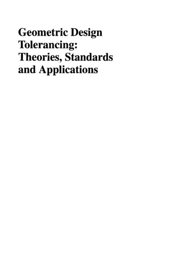
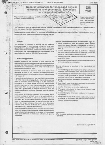
were introduced to standardize the graphical communication of geometric informationbetween designers, manufacturing, and quality control people.To make sure that the parts were made with sufficient accuracy to fit together duringassembly, design engineers had functional gages built and sent with their drawings thatdescribed the part dimensions. Each functional feature of a part was to be checked withtwo types of physical gages, a GO gage and a NOT GO gage. A part that would fit theGO gage was assured to fit a mating part in the assembly. The GO gage, sometimesmade of wood, simply represented the worst-case geometry of a mating part for fitpurposes. Figure 1-1 shows a portion of a chainsaw assembly.Figure 1-1. A portion of a chainsaw assemblyFigure 1-2 shows a chainsaw link with its two critical holes along with a GO gage whichis a flat plate with two pins. GO gages simulate the contacting surfaces and fittingfeatures of a mating part.7
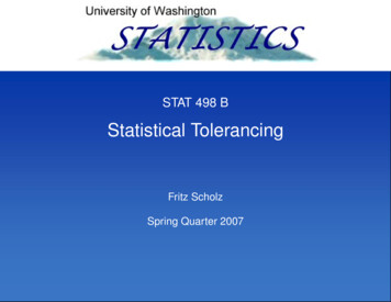
Figure 1-2. The chainsaw link and a GO gage checking its fit to a mating partGO gages check the fit of a feature into assembly but they do not check for excessiveplay in the fit when the holes are too large. NOT GO gages were used to make sure theholes were not too large. A hole that would go through a NOT GO gage was too largeleading to a loose fit and creating too much slack or play to be functionally acceptable.The NOT GO gage for the chain link is a plug gage that is used individually on each hole.The chain link and the plug gage are shown in Figure 1-3.8
Figure 1-3. A NOT GO plug gage for checking the size of each hole in the chainsaw linkAn acceptable part feature would clear the GO gage, assuring fit, but not the NOT GOgage, assuring acceptable play and proper function. Other non-critical features of partswere assumed to be acceptable as made when the tools and workmanship conformed toestablished standards of good manufacturing. No gages were made for non-criticalfeatures.Building and sending physical gages with part drawings were difficult to do in a designenvironment. In later years, design engineers simply created separate drawings necessaryto build the gages at the manufacturing site with some added precision instructions. Theprecision instructions, or tolerancing instructions, were in the form of variation limitson the dimensions of the gages to be made. With this additional description of accuracy,the gages could be built at the manufacturing site where the parts were being made.Eventually, these limits were directly applied to the part dimensions from whichappropriate gages could be made to verify the fit and function of precision features. Thiseliminated the need for the designers to create multiple sets of drawings, one for the partand others for the gages. It also became easy to simply check the dimensions of the partfor conformance. Unfortunately, this practice led to serious unintended consequences.Applying dimension limits by designers and checking dimensions by inspectors becamethe norm in tolerancing until it was replaced by geometric tolerancing practices that onceagain introduced the concepts of functional gaging back into the tolerancing standardsand tolerancing practice.9
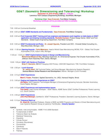
1.3.Geometric versus dimensional tolerancesAt the time of its introduction, the geometric variation control based on limits on partdimensions and angles were logical extensions of dimensioning, easy to apply, easy tounderstand, and easy to verify. However, the ease of dealing with dimension limits istrue only when the geometry of the part remains free of deformations and distortions.Deformations and distortions make it difficult to interpret the meaning of dimensionlimits without subjectivity. As more knowledge was gained regarding the geometricrequirements of fit and function, it became clear that dimensional tolerances alone did notprovide the best specification toolbox for assuring fit and function.The concept of gaging and gage description is at the heart of what constitutes geometrictolerancing. A simple example can highlight the advantage of geometric tolerancingover just using dimension limits. Consider rolling a heavy, tall refrigerator on casterspast a doorway. The width of the refrigerator is just below 835 mm and the width of thedoorway is just over 835 mm. There is a good chance, however, that the refrigeratorwould not fit through. Figure 1-4 highlights the point.Figure 1-4. The width of the refrigerator alone may not be sufficient to assure fitOn the left figure, the refrigerator and the doorway are shown to be free from alldistortions. In reality, however, this never happens. On the right figure the refrigerator istilted slightly to the left with respect to the plane of casters, while the doorway isassumed to be free of distortions. The resulting arrangement leads to interference.10
You can imagine how specifying the “width” dimension limits alone can put fit ability injeopardy. The homeowner who wants to assure fit using dimension limits must alsospecify or explain to measure the width correctly as shown in Figure 1-5.840830834Figure 1-5. The width of the refrigerator must be measured in a way that is meaningful for fitOf the three methods of measurement shown, only the 840 mm value is functionallycorrect for fit. The other two measurements, albeit both reasonable measurements of the“width” of the refrigerator, lead to incorrect values for fit. A tolerancing scheme basedon dimension limits simply ignores the reality that parts can have deformations anddistortions. You may describe the required method of measurement by notes but theGDT standard provides an elegant way of describing exactly such a fit requirement usinga compact symbolic notation.By making gages, the dimensional measurement confusion would never happen. Thegage for the refrigerator would be a perfect 835 mm doorway as high as the refrigeratorand made nearly perfectly with gage-making tolerances. If the refrigerator passesthrough this gage properly, it would also pass though the real doorway. Note that thegage geometry description by itself is not sufficient to assure a correct fit. The gaginginstructions are necessary to ensure the refrigerator passes through the gage while castersare in contact with the floor. The GDT standard provides a set of symbols to easilydescribe the gages and the gaging methods for common fit applications in assemblies.The strength of the GDT standard specifications is that it allows a designer to specify the11
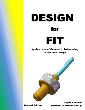
precision needs of a part by following and mimicking the way the part is intended to fitinto an assembly.Unlike dimensional tolerances, geometric tolerancing statements do not ask for anynumerical measurements at all. They simply describe the geometry of the necessarygages to assure fit and function. Of course an inspector who does not want to build agage, for cost or practical reasons, is forced to make the necessary measurements to beable to judge with confidence whether the feature would pass such a gage if it had beenmade. In the case of the refrigerator, the inspector may easily measure the width of 830mm and also measure the angle of tilt. Combing the two measurements would comeclose to the functional dimension of the refrigerator.In design, the basic elements of function are features. Features are collections ofsurfaces that, as a whole, can be associated with a particular function. This is similar tothe use of language in which the basic elements of communication are words notindividual letters. A feature-based geometric specification language directly deals withfeatures and their functions. The geometric tolerancing standard provides this featurebased language and a gage-based methodology for geometry control. Geometrictolerancing allows the design engineers to separately control various geometry aspects offeatures when needed. Such aspects include feature size, form, orientation, and location.Today, the preferred method of specifying acceptable manufacturing tolerances is acombination of geometric and dimensional tolerances. Dimensional tolerances aremainly used to describe size limits of cylindrical features or width features (slots andrails). Figure 1-6, for example, shows both the dimensional and the geometrictolerancing methods of controlling the size and the distance between two holes. Thegeometric method will be explained later in detail.12
Figure 1-6. Specifying the tolerance on the distance between two holes using dimensionaltolerancing (top) and geometric tolerancing meth
for teaching mechanical tolerancing for nearly thirty years. The book’s emphasis is on fit and alignment requirements for machine components. Fit assurance makes up the majority of challenging applications in tolerancing. Design for specific functions is easy by comparison. For design engineers, knowi