Transcription
Member ofwww.eota.euTechnical and Test Institutefor Construction PragueProsecká 811/76a190 00 PragueCzech Republiceota@tzus.czEuropean TechnicalAssessmentETA 20/0980of 06/01/2021Technical Assessment Body issuing the ETA: Technical and Test Institutefor Construction PragueTrade name of the construction productJCP Epoxy Resin JF250EProduct family to which the constructionproduct belongsProduct area code: 33Bonded injection type anchor for use incracked and uncracked concreteManufacturerHexstone Ltd. T/A JCP Construction ProductsOpal Way, Stone Business ParkStone, Staffordshire, ST15 OSWUnited KingdomManufacturing plantJCP Construction ProductsThis European Technical Assessmentcontains18 pages including 15 Annexes which forman integral part of this assessment.This European Technical Assessment isissued in accordance with regulation(EU) No 305/2011, on the basis ofEAD 330499-01-0601 Bonded fasteners foruse in concreteTranslations of this European Technical Assessment in other languages shall fully correspond to the original issueddocument and should be identified as such.Communication of this European Technical Assessment, including transmission by electronic means, shall be infull (excepted the confidential Annex(es) referred to above). However, partial reproduction may be made, with thewritten consent of the issuing Technical Assessment Body - Technical and Test Institute for Construction Prague.Any partial reproduction has to be identified as such.ETA 20/0980 of 06/01/2021 – Page 1 of 18090-050203
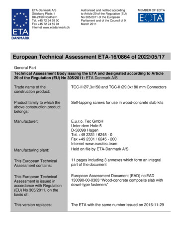
1.Technical description of the productThe JCP Epoxy Resin JF250E with steel elements is bonded anchor (injection type).Steel elements can be galvanized or stainless steel threaded rod or rebar.Steel element is placed into a drilled hole filled with injection mortar. The steel elementis anchored via the bond between metal part, injection mortar and concrete. The anchoris intended to be used with embedment depth from 4 diameters to 20 diameters.The illustration and the description of the product are given in Annex A.2.Specification of the intended use in accordance with the applicable EADThe performances given in Section 3 are only valid if the anchor is used in compliancewith the specifications and conditions given in Annex B.The provisions made in this European Technical Assessment are based on anassumed working life of the anchor of 50 years. The indications given on the workinglife cannot be interpreted as a guarantee given by the producer, but are to be regardedonly as a means for choosing the products in relation to the expected economicallyreasonable working life of the works.3.Performance of the product and references to the methods used for itsassessment3.1Mechanical resistance and stability (BWR 1)Essential characteristicStatic and quasi-static loadingResistance to steel failure (tension)Resistance to combined pull-out and concrete failureResistance to concrete cone failureEdge distance to prevent splitting under loadRobustnessMaximum setting torque momentMinimum edge distance and spacingResistance to steel failure (shear)Resistance to pry-out failureResistance to concrete edge failureDisplacements under short term and long term loadingDurability of metal partsSeismic performance C1Resistance to steel failureResistance to pull-outFactor for annular gapPerformanceSee Annex C1, C2See Annex C1, C2See Annex C1, C2See Annex C1, C2See Annex C1, C2See Annex B3See Annex B3See Annex C3, C4See Annex C3, C4See Annex C3, C4See Annex C5, C6See Annex A3See Annex C7See Annex C7See Annex C73.2Hygiene, health and environment (BWR 3)No performance determined.3.3General aspects relating to fitness for useDurability and serviceability are only ensured if the specifications of intended useaccording to Annex B 1 are kept.ETA 20/0980 of 06/01/2021 – Page 2 of 18
4.Assessment and verification of constancy of performance (AVCP) systemapplied with reference to its legal baseAccording to the Decision 96/582/EC of the European Commission1 the system ofassessment verification of constancy of performance (see Annex V to Regulation (EU)No 305/2011) given in the following table apply.ProductIntended useLevel or class SystemMetal anchors for For fixing and/or supporting to concrete,use in concretestructural elements (which contributes to1the stability of the works) or heavy units5.Technical details necessary for the implementation of the AVCP system, asprovided in the applicable EAD5.1Tasks of the manufacturerThe manufacturer may only use raw materials stated in the technical documentation of thisEuropean Technical Assessment.The factory production control shall be in accordance with the control plan which is a partof the technical documentation of this European Technical Assessment. The control planis laid down in the context of the factory production control system operated by themanufacturer and deposited at Technical and Test Institute for Construction Prague.2 Theresults of factory production control shall be recorded and evaluated in accordance withthe provisions of the control plan.5.2Tasks of the notified bodiesThe notified body shall retain the essential points of its actions referred to above andstate the results obtained and conclusions drawn in a written report.The notified certification body involved by the manufacturer shall issue a certificate ofconstancy of performance stating the conformity with the provisions of this EuropeanTechnical Assessment.In cases where the provisions of the European Technical Assessment and its controlplan are no longer fulfilled the notified body shall withdraw the certificate of constancyof performance and inform Technical and Test Institute for Construction Prague withoutdelay.Issued in Prague on 06.01.2021Head of the Technical Assessment Body12Official Journal of the European Communities L 254 of 08.10.1996The control plan is a confidential part of the documentation of the European Technical Assessment, but notpublished together with the ETA and only handed over to the approved body involved in the procedure of AVCP.ETA 20/0980 of 06/01/2021 – Page 3 of 18
Threaded rodReinforcing barJCP Epoxy Resin JF250EProduct descriptionInstalled conditionsETA 20/0980 of 06/01/2021 – Page 4 of 18Annex A 1
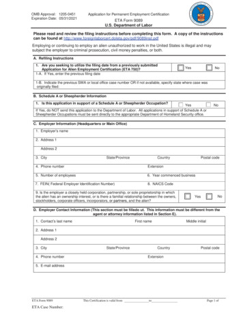
CartridgesUniversal cartridgeJCP Epoxy Resin JF250E 250 mlMarking of the mortar cartridgesIdentifying mark of the producer, Trade name, Charge code number, Storage life, Curing andprocessing timeMixing nozzleStandard Mixing NozzleLong Mixing NozzleJCP Epoxy Resin JF250EProduct descriptionInjection systemETA 20/0980 of 06/01/2021 – Page 5 of 18Annex A 2
Threaded rod M10, M12, M16, M20, M24, M30Standard commercial threaded rod with marked embedment depthPart DesignationMaterialSteel, zinc plated 5 µm acc. to EN ISO 4042 orSteel, Hot-dip galvanized 40 µm acc. to EN ISO 1461 and EN ISO 10684Steel, EN 10087 or EN 102631Anchor rodProperty class 5.8, 8.8, 10.9* EN ISO 898-1Hexagon nut2According to threaded rod, EN 20898-2EN ISO 4032Washer3According to threaded rodEN ISO 887, EN ISO 7089,EN ISO 7093 or EN ISO 7094Stainless steel1Anchor rodHexagon nutEN ISO 4032Washer3EN ISO 887, EN ISO 7089,EN ISO 7093 or EN ISO 7094High corrosion resistant steel 1.452921Anchor rodMaterial: A2-70, A4-70, A4-80, EN ISO 3506According to threaded rodAccording to threaded rodMaterial: 1.4529, EN 10088-1Hexagon nutAccording to threaded rodEN ISO 4032Washer3EN ISO 887, EN ISO 7089,According to threaded rodEN ISO 7093 or EN ISO 7094*Galvanized rod of high strength are sensitive to hydrogen induced brittle failure2JCP Epoxy Resin JF250EProduct descriptionThreaded rod and materialsETA 20/0980 of 06/01/2021 – Page 6 of 18Annex A 3
Rebar Ø10, Ø12, Ø16, Ø20, Ø25, Ø32Standard commercial reinforcing bar with marked embedment depthProduct formClassCharacteristic yield strength fyk or f0,2k (MPa)Minimum value of k (ft/fy)kCharacteristic strain at maximum force εuk (%)BendabilityMaximum deviation from nominal Nominal bar size (mm)mass (individual bar) (%) 8 8Bond: Minimum relative rib area,Nominal bar size (mm)fR,min8 to 12 12Bars and de-coiled rodsBC400 to 600 1,15 1,08 1,35 5,0 7,5Bend/Rebend test 6,0 4,50,0400,056JCP Epoxy Resin JF250EProduct descriptionRebars and materialsETA 20/0980 of 06/01/2021 – Page 7 of 18Annex A 4
Specifications of intended useAnchorages subject to: Static and quasi-static load. Seismic actions category C1 (max w 0,5 mm): threaded rodsBase materials Cracked and uncracked concrete. Reinforced or unreinforced normal weight concrete of strength class C20/25 at minimum andC50/60 at maximum according EN 206-1:2000-12.Temperature range: Ta) -40 C to 40 C (max. short. term temperature 40 C and max. long term temperature 24 C) Tb) -40 C to 70 C (max. short. term temperature 70 C and max. long term temperature 40 C) Tc) -40 C to 80 C (max. short. term temperature 80 C and max. long term temperature 40 C)Use conditions (Environmental conditions) (X1) Structures subject to dry internal conditions (zinc coated steel, stainless steel, high corrosionresistance steel). (X2) Structures subject to external atmospheric exposure (including industrial and marineenvironment) and to permanently damp internal condition, if no particular aggressive conditionsexist (stainless steel A4, high corrosion resistant steel). (X3) Structures subject to external atmospheric exposure and to permanently damp internalcondition, if other particular aggressive conditions exist (high corrosion resistant steel).Note: Particular aggressive conditions are e.g. permanent, alternating immersion in seawater or thesplash zone of seawater, chloride atmosphere of indoor swimming pools or atmosphere with extremechemical pollution (e.g. in desulphurization plants or road tunnels where de-icing materials are used).Concrete conditions: I1 – installation in dry or wet (water saturated) concrete and use in service in dry or wet concrete.Design: The anchorages are designed in accordance with the EN 1992-4 under the responsibility of anengineer experienced in anchorages and concrete work. Verifiable calculation notes and drawings are prepared taking account of the loads to be anchored.The position of the anchor is indicated on the design drawings. Anchorages under seismic actions (cracked concrete) have to be designed in accordance with EN1992-4.Installation: Hole drilling by hammer drill mode. Anchor installation carried out by appropriately qualified personnel and under the supervision of theperson responsible for technical matters of the site.Installation direction: D3 – downward and horizontal and upwards (e.g. overhead) installationJCP Epoxy Resin JF250EIntended useSpecificationsETA 20/0980 of 06/01/2021 – Page 8 of 18Annex B 1
Applicator gunCleaning brushSizeSteel brush head diameterSteel brush head lengthMin. overall brush lengthSizeSteel brush head diameterSteel brush head lengthMin. overall brush 5110JCP Epoxy Resin JF250EIntended useApplicator gunsCleaning brushETA 20/0980 of 06/01/2021 – Page 9 of 18Annex B 2
Table B1: Installation parameters of threaded rodSizeNominal drill hole diameterDiameter of cleaning brushTorque momentDepth of drill hole for hef,minDepth of drill hole for hef,maxMinimum edge distanceMinimum spacingMinimum thickness of memberM10Ød0dbmax Tfixh0 hefh0 hefcminsminhminM12M16M20M24M30[mm]121418222635[mm] S14H/F S16H/F S22H/F S24H/F S31H/F hef 30 mm 100 mmhef 2d0Table B2: Installation parameters of rebarSizeNominal drill hole diameterDiameter of cleaning brushTorque momentDepth of drill hole for hef,minDepth of drill hole for hef,maxMinimum edge distanceMinimum spacingMinimum thickness of memberØ10Ød0dbTinsth0 hefh0 0[mm] S16H/F S18H/F S22H/F S27H/F S35H/F ]hef 30 mm 100 mmhef 2d0Table B3: Minimum curing timeConcrete temperatureGel timeCure time[ C][minutes][hours] 5 to 102420 10 to 1512 15 to 20158 20 to 25117 25 to 3086 30 to 3565 35 to 4044 4033Cartridge must be conditioned to minimum 10 CJCP Epoxy Resin JF250EIntended useInstallation parametersCuring timeETA 20/0980 of 06/01/2021 – Page 10 of 18Annex B 3
Installation procedureBefore commencing installation ensure the operative is equipped with appropriate personal protection equipment, SDS Hammer Drill, Air, HoleCleaning Brush, good quality Dispensing Tool – either manual or power operated, Chemical cartridge with mixing nozzle and extension tube,if needed.1. Using the SDS Hammer Drillin rotary hammer mode fordrilling, with a carbide tippeddrill bit of the appropriate size,drill the hole to the specifiedhole diameter and depth.2. Insert the Air Lance to thebottom of the hole anddepress the trigger for 2seconds. The compressed airmust be clean – free fromwater and oil – and at aminimum pressure of 6bar.Perform the blowing operation twice.3. Select the correct size HoleCleaning Brush. Ensure thatthe brush is in good conditionand the correct diameter.Insert the brush to the bottomof the hole, using a brushextension if needed to reach the bottom of the holeand withdraw with a twisting motion. There shouldbe positive interaction between the steel bristles ofthe brush and the sides of the drilled hole.Perform the brushing operation twice.4. Repeat 25. Repeat 36. Repeat 27. Select the appropriate static mixernozzle, checking that the mixingelements are present and correct(do not modify the mixer). Attachmixer nozzle to the cartridge. Checkthe Dispensing Tool is in goodworking order. Place the cartridgeinto the dispensing tool.Note: The Long Mixing Nozzle is intwo sections. One section containsthe mixing elements and the othersection is an extension piece.Connect the extension piece to themixing section by pushing the twosections firmly together until a positive engagementis felt.8. Extrude some resin to waste until an even-coloredmixture is extruded, The cartridge is now readyfor use9. Attach an extension tube withresin stopper (if required) tothe end of the mixing nozzlewith a push fit(The extension tubes may be pushed into the resinstoppers and are held in place with a coarse internalthread).10. Insert the mixing nozzle to thebottom of the hole. Extrudethe resin and slowly withdrawthe nozzle from the hole.Ensure no air voids arecreated as the nozzle iswithdrawn. Inject resin untilthe hole is approximately ¾ full and remove thenozzle from the hole.11. Select the steel anchorelement ensuring it is freefrom oil or other contaminants,and mark with the requiredembedment depth. Insert thesteel element into the holeusing a back and forth twistingmotion to ensure complete cover, until it reaches thebottom of the hole. Excess resin will be expelledfrom the hole evenly around the steel element andthere shall be no gaps between the anchor elementand the wall of the drilled hole.12. Clean any excess resin from around the mouth ofthe hole.13. Do not disturb the anchor untilat least the minimum curetime has elapsed. Refer tothe Working and LoadTimetable to determine theappropriate cure time.14. Position the fixture and tightenthe anchor to the appropriateinstallation torque.Do not over-torque theanchor as this couldadversely affect itsperformance.JCP Epoxy Resin JF250EIntended useInstallation instructionsETA 20/0980 of 06/01/2021 – Page 11 of 18Annex B 4
Table C1: Design method EN 1992-4Characteristic values of resistance to tension load of threaded rodSteel failure – Characteristic resistanceSizeSteel grade 5.8NRk,sγMsPartial safety factorSteel grade 8.8NRk,sγMsPartial safety factorSteel grade 10.9*NRk,sγMsPartial safety factorStainless steel grade A2-70, A4-70NRk,sγMsPartial safety factorStainless steel grade A4-80NRk,sγMsPartial safety factorStainless steel grade 1.4529NRk,sγMsPartial safety 261,641591101,5Combined pullout and concrete cone failure in uncracked concrete C20/25SizeM10 M12 M16 M20Characteristic bond resistance in uncracked concrete C20/25τRk,ucr [N/mm2] 11Temperature a) -40 C to 40 C111111τRk,ucr [N/mm2]Temperature b) -40 C to 70 C5555τRk,ucr [N/mm2] 4,5Temperature c) -40 C to 80 C444Installation safety factorγinst[-]1,21,4Factor for uncracked concrete C30/371,12Factor for uncracked concrete C40/50ψc1,23Factor for uncracked concrete C50/601,30Characteristic bond resistance in cracked concrete C20/25τRk,cr [N/mm2] 8,5Temperature a) -40 C to 40 C8,58,55,5τRk,cr [N/mm2] 3,5Temperature b) -40 C to 70 C3,542τRk,cr [N/mm2]Temperature c) -40 C to 80 C3332γinstPartial safety factor[-]1,21,4Factor for cracked concrete C30/371,03Factor for cracked concrete C40/50ψc1,06Factor for cracked concrete C50/601,07Concrete cone failureFactor for concrete cone failurefor uncracked concreteFactor for concrete cone failurefor cracked concreteEdge distancekucr,N11[-]kcr,Nccr,N7,7[mm]Splitting failureSize1,5hefM10Edge distanceccr,sp[mm]Spacingscr,sp[mm]M12M16M20 h1,0 hef 2,0 hef 2,5 hef 2, 4 hef 2 Ccr,spJCP Epoxy Resin JF250EPerformancesDesign according to EN 1992-4Characteristic resistance for tension loads - threaded rodETA 20/0980 of 06/01/2021 – Page 12 of 18Annex C 1
Table C2: Design method EN 1992-4Characteristic values of resistance to tension load of rebarSteel failure – Characteristic resistanceSizeRebar BSt 500 SNRk,sγMsPartial safety factor[kN][-]Ø1043Ø1262Ø16 Ø201111731,4Combined pullout and concrete cone failure in uncracked concrete C20/25SizeØ10 Ø12 Ø16 Ø20Characteristic bond resistance in uncracked concrete C20/25τRk,ucr [N/mm2] 11Temperature a) -40 C to 40 C111212τRk,ucr [N/mm2]Temperature b) -40 C to 70 C555,55,5τRk,ucr [N/mm2] 4,5Temperature c) -40 C to 80 C4,54,54,5Installation safety factorγinst[-]1,21,4Factor for uncracked concrete C30/371,06Factor for uncracked concrete C40/50ψc1,11Factor for uncracked concrete C50/601,14Characteristic bond resistance in cracked concrete C20/25τRk,cr [N/mm2] 8,5Temperature a) -40 C to 40 C8,56,56,5τRk,cr [N/mm2] 3,5Temperature b) -40 C to 70 C3,52,52,5τRk,cr [N/mm2]Temperature c) -40 C to 80 C3322γinstPartial safety factor[-]1,21,4Factor for cracked concrete C30/371,04Factor for cracked concrete C40/50ψc1,07Factor for cracked concrete C50/601,09Concrete cone failureFactor for concrete cone failurefor uncracked concreteFactor for concrete cone failurefor cracked concreteEdge Splitting failureSize1,5hefØ10Edge distanceccr,sp[mm]Spacingscr,sp[mm]Ø12Ø16Ø20 h1,0 hef 2,0 hef 2,5 hef 2, 4 hef 2 Ccr,spJCP Epoxy Resin JF250EPerformancesDesign according to EN 1992-4Characteristic resistance for tension loads - rebarETA 20/0980 of 06/01/2021 – Page 13 of 18Annex C 2
Table C3: Design method EN 1992-4Characteristic values of resistance to shear load of threaded rodSteel failure without lever armSizeM10 M12Steel grade 5.8VRk,s [kN]1521γMs [-]Partial safety factorSteel grade 8.8VRk,s [kN]2334γMs [-]Partial safety factorSteel grade 10.9*VRk,s [kN]2942γMs [-]Partial safety factorStainless steel grade A2-70, A4-70VRk,s [kN]2030γMs [-]Partial safety factorStainless steel grade A4-80VRk,s [kN]2334γMs [-]Partial safety factorStainless steel grade 1.4529VRk,s [kN]2030γMs [-]Partial safety factorCharacteristic resistance of group of fastenersDuctility factor k7 1,0 for steel with rupture elongation A5 8%Steel failure with lever armSizeSteel grade 5.8Partial safety factorSteel grade 8.8Partial safety factorSteel grade 10.9*Partial safety factorStainless steel grade A2-70, A4-70Partial safety factorStainless steel grade A4-80Partial safety factorStainless steel grade 1.4529Partial safety factorConcrete pryout failureFactor for resistance to pry-out failureConcrete edge failureSizeOutside diameter of fastenerEffective length of fastenerMoRk,sγMsoM Rk,sγMsMoRk,sγMsMoRk,sγMsMoRk,sγMsoM [N.m][-]M1037M126660105751315292601055292[-]dnom [mm]ℓf [mm]M16 5M2488M30140141224177281124196141224124196M16 M20166 3251,25266 5191,25333 6491,50233 4541,56266 5191,33233 4541,25M24561M30112589817991123 2249786157489817997861574M16 M20 M24162024min (hef, 8 dnom)M30302M1010M1212JCP Epoxy Resin JF250EPerformancesDesign according to EN 1992-4Characteristic resistance for shear loads - threaded rodETA 20/0980 of 06/01/2021 – Page 14 of 18Annex C 3
Table C4: Design method EN 1992-4Characteristic values of resistance to shear load of rebarSteel failure without lever armSizeØ10 Ø12Rebar BSt 500 SVRk,s [kN]2231γMs [-]Partial safety factorCharacteristic resistance of group of fastenersDuctility factor k7 1,0 for steel with rupture elongation A5 8%Steel failure with lever armSizeRebar BSt 500 SPartial safety factorConcrete pryout failureFactor for resistance to pry-out failureConcrete edge failureSizeOutside diameter of fastenerEffective length of fastenerMoRk,s [N.m]γMs [-]k8Ø1065Ø12112[-]dnom [mm]ℓf [mm]Ø16 Ø2055861,5Ø25135Ø32221Ø16 Ø202655181,5Ø25 Ø321013 21222Ø1010Ø1212Ø16 Ø20 Ø25162025min (hef, 8 dnom)Ø3232JCP Epoxy Resin JF250EPerformancesDesign according to EN 1992-4Characteristic resistance for shear loads - rebarETA 20/0980 of 06/01/2021 – Page 15 of 18Annex C 4
Table C5: Displacement of threaded rodTension loadAnchor sizeUncracked concreteδN040 C / 24 CδN δN070 C / 40 CδN δN080 C / 40 CδN Cracked concreteδN040 C / 24 CδN δN070 C / 40 CδN δN080 C / 40 CδN 160,320,090,170,050,110,040,080,040,08Shear loadAnchor sizeUncracked concreteδV0All temperaturesδV [mm/(N/mm2)][mm/(N/mm2)]JCP Epoxy Resin JF250EPerformancesDisplacement for threaded rodETA 20/0980 of 06/01/2021 – Page 16 of 18Annex C 5
Table C6: Displacement of rebarTension loadAnchor sizeUncracked concreteδN040 C / 24 CδN δN070 C / 40 CδN δN080 C / 40 CδN Cracked concreteδN040 C / 24 CδN δN070 C / 40 CδN δN080 C / 40 CδN Shear loadAnchor sizeUncracked concreteδV0All temperaturesδV [mm/(N/mm2)][mm/(N/mm2)]JCP Epoxy Resin JF250EPerformancesDisplacement for rebarETA 20/0980 of 06/01/2021 – Page 17 of 18Annex C 6
Table C7: Reduction factors for seismic design category C1 for threaded rodsSizeTension loadSteel failureCharacteristic resistance grade 5.8NRk,s,eq [kN]Characteristic resistance grade 8.8NRk,s,eq [kN]Characteristic resistance grade 10.9NRk,s,eq [kN]Characteristic resistance A2-70, A4-70NRk,s,eq [kN]Characteristic resistance A4-80NRk,s,eq [kN]Characteristic resistance 1.4529NRk,s,eq [kN]Combined pull-out and concrete cone failureFactor for calculation of τRk,eq1)αN,seis Shear loadSteel failure without lever armCharacteristic resistance grade 5.8VRk,s,eq [kN]Characteristic resistance grade 8.8VRk,s,eq [kN]Characteristic resistance grade 10.9VRk,s,eq [kN]Characteristic resistance A2-70, A4-70VRk,s,eq [kN]Characteristic resistance A4-80VRk,s,eq [kN]Characteristic resistance 1.4529VRk,s,eq [kN]αgap [-]Factor for annular gap1)τRk,eq αN,seis x ,4280,5196,4224,4196,40,5Note: Rebars are not qualified for seismic designJCP Epoxy Resin JF250EPerformancesReduction factors for seismic designETA 20/0980 of 06/01/2021 – Page 18 of 18Annex C 7
Threaded rod M10, M12, M16, M20, M24, M30 Standard commercial threaded rod with marked embedment depth Part Designation Material Steel, zinc plated 5 µm acc. to EN ISO 4042 or Steel, Hot-dip galvanized 40 µm acc. to EN ISO 1461 and EN ISO 10684 1 Anchor rod Steel, EN 10087 or EN 10263 Property class 5.8, 8.8, 10.9* EN ISO 898-1 2