Transcription
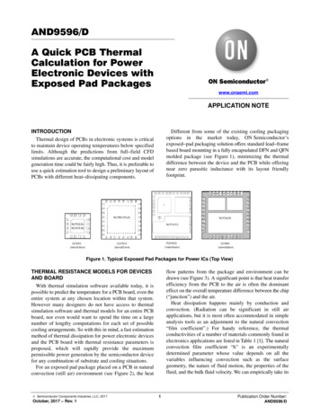
AND9596/DA Quick PCB ThermalCalculation for PowerElectronic Devices withExposed Pad Packageswww.onsemi.comAPPLICATION NOTEINTRODUCTIONThermal design of PCBs in electronic systems is criticalto maintain device operating temperatures below specifiedlimits. Although the predictions from full field CFDsimulations are accurate, the computational cost and modelgeneration time could be fairly high. Thus, it is preferable touse a quick estimation tool to design a preliminary layout ofPCBs with different heat dissipating components.Different from some of the existing cooling packagingoptions in the market today, ON Semiconductor’sexposed pad packaging solution offers standard lead framebased board mounting in a fully encapsulated DFN and QFNmolded package (see Figure 1), minimizing the thermaldifference between the device and the PCB while offeringnear zero parasitic inductance with its layout friendlyfootprint.Figure 1. Typical Exposed Pad Packages for Power ICs (Top View)THERMAL RESISTANCE MODELS FOR DEVICESAND BOARDWith thermal simulation software available today, it ispossible to predict the temperature for a PCB board, even theentire system at any chosen location within that system.However many designers do not have access to thermalsimulation software and thermal models for an entire PCBboard, nor even would want to spend the time on a largenumber of lengthy computations for each set of possiblecooling arrangements. So with this in mind, a fast estimationmethod of thermal dissipation for power electronic devicesand the PCB board with thermal resistance parameters isproposed, which will rapidly provide the maximumpermissible power generation by the semiconductor devicefor any combination of substrate and cooling situations.For an exposed pad package placed on a PCB in naturalconvection (still air) environment (see Figure 2), the heat Semiconductor Components Industries, LLC, 2017October, 2017 Rev. 1flow patterns from the package and environment can bedrawn (see Figure 3). A significant point is that heat transferefficiency from the PCB to the air is often the dominanteffect on the overall temperature difference between the chip(“junction”) and the air.Heat dissipation happens mainly by conduction andconvection. (Radiation can be significant in still airapplications, but it is most often accommodated in simpleanalysis tools as an adjustment to the natural convection“film coefficient”.) For handy reference, the thermalconductivities of a number of materials commonly found inelectronics applications are listed in Table 1 [1]. The naturalconvection film coefficient “h” is an experimentallydetermined parameter whose value depends on all thevariables influencing convection such as the surfacegeometry, the nature of fluid motion, the properties of thefluid, and the bulk fluid velocity. We can empirically take its1Publication Order Number:AND9596/D
AND9596/Dvalue as 15, 30, 45 W/(m2K) for air velocities of 0, 1.0,2.5 m/s [2]. (As noted above, for air velocities lower than1 m/s, a significant fraction of this coefficient, as much as35 40%, may actually be due to radiation, so surfaceemissivity may need to be considered. Shiny, metallicsurfaces tend to have lower radiation contribution;matte finish, non metallic surfaces tend to have higherradiation contribution).A four resistor simplified equivalent thermal networkdiagram of the package and environment can be drawn (seeFigure 4) with the package represented by a two resistormodel [3]. The die represents the junction node, whereas thecase top and exposed pad in the bottom plate represent the“Case Node” and “Board Node” in the diagram,respectively.Table 1. MATERIAL THERMAL CONDUCTIVITY PROPERTIESMaterialThermal Conductivity (W/mK)Silicon145Mold Compound0.7Lead Frame277Die Attach Epoxy2.4Copper388FR4 PCB0.35SnAgCu Solder57.363Sn37Pb Colder50Figure 2. Exposed Pad Package on PCBFigure 3. The Heat Flow Directions (Red Arrows)www.onsemi.com2
AND9596/DFigure 4. Equivalent Thermal Resistance Diagram of the Modified Two resistor Model on a PCB4. JA JB BASimple analysis of the four resistor thermalnetwork (Figure 4) shows that:In many applications of exposed pad packages, it ispossible further to simplify this network from four resistorsdown to two resistors. Several reasonable approximationsmay be considered to justify this:1. B TCbottom and JB JCbottomThe exposed pad packages are designed to injectheat directly into the copper plane of the board viabottom pad, and the effect of solder between thepackage pad and PCB pad is neglected due to itsthin and with not bad thermal conductioncapability. So the bottom of the exposed pad canbe taken to be the board temperature, that is B TCbottom and JB JCbottom .2. JCtop JBTake 6 6 mm QFN package of the NCP323X ina natural air environment, for example, we have JCtop 22 C/W, while JB JCbottom ,(from approximation 1) is only 1.3 C/W.Thus JCtop JB .3. CA BABecause convection resistances are inverselyproportional to the exposed heat transfer surfacearea, as a general rule PCB convection resistanceto air is much lower than case thermal resistance toair. For example, the total area of both sides ofa 50 50 mm PCB is 5000 mm2, whereas thesurface area of a 6 6 mm QFN is only 36 mm2.Clearly, CA BA .q JA (q JB ) q BA) ø (q JCtop ) q CA)(eq. 1)From the 2nd and 3rd approximations above,( JB BA ) ( JCtop CA ). Thus Eq.1 can besimplified as:q JA q JB ) q BA(eq. 2)This means for exposed pad packages thedominant heat dissipation path is through the PCBvia the bottom pad to ambient.In summary, then, when JB can be read from a datasheet,as, for example, the NCP81295, then only BA remains todetermine the total package/PCB system thermal resistance.Another useful approximation with respect to thefour resistor package/PBC system is J TC .Using the same 6 6 mm QFN example, the junction ( J )to case top (TC ), thence to ambient (TA ), thermal resistancescan be calculated by conduction and convection principles.This yields the result of JC 22 C/W vs. CA 1300 C/W.By voltage divider analogy, the difference TJC is thus onlyabout (22/(1300 22)) 1.7% of the total TJA . If thejunction was 100 C above ambient, then the differencebetween junction and case would be less than 2 C.Table 2. THERMAL CHARACTERISTICSRatingSymbolValueUnitThermal Resistance, Junction to AmbientRqJA30 C/WThermal Resistance, Junction to Top CaseRqJCT50 C/WThermal Resistance, Junction to Bottom CaseRqJCB1.5 C/WThermal Resistance, Junction to BoardRqJR1.5 C/WThermal Resistance, Junction to CaseRqJC1.5 C/Wwww.onsemi.com3
AND9596/DCalculation of Thermal Resistor of Board toAmbient (qBA)θ ab BA represents the thermal resistance of the PCB, from thepoint at which the package puts heat into the board, toambient. Different board sizes and properties have different BA values. Consider a simple axisymmetric model of a PCBboard as shown in Figure 5. What is particularly helpfulabout the axisymmetric model [4] is the outer edge of theboard will be an isotherm by definition. In this model, thepower IC chip can be taken as an axisymmetric heat sourceat the inner radius (the package), and at the exterior circularperimeter of the board we will specify a temperature riseabove ambient, and also possibly a heat flow from the edge.Between the inner and outer radii, board properties areuniform, and heat is lost continuously to convection,characterized by a constant film coefficient. When the heatloss at the outer perimeter is zero, the thermal resistance ofboard to ambient is calculated from the circular fin formula:The thermal resistance of board to ambient of this circleregion is calculated from the circular fin formula:12paktaK 1(ab) I 0(aa) ) I 1(ab) K 0(aa)I 1(ab) K 1(aa) * I 1(aa) K 1(ab)(eq. 3)where: I0 (), I1 ()are the 1st kind modified Bessel functions,0 and 1 order; K0 (), K1 ()are the 2nd kind modified Bessel functions,0 and 1 order; k is the thermal conductivity of the PCB[15, 20, 50W/(mK) for 2, 3, 8 oz board, respectively]; t is PCB board thickness; a Ǹ(Nh)ń(kt), N is the number of surfaces cooled by h; h is the convection film coefficient (including radiationeffect, if important);a and b are each the inner and outer radius,respectively.abFigure 5. The Axisymmetric Model for Thermal Resistance of a PCBof copper plane, size/number of thermal vias, and copperplane pattern. The detailed modeling for thermalconductivity of the board is shown in Figure 6. It can betaken for equivalent thermal conductivity k calculations.While this formula may appear intimidating, Besselfunctions are available in popular spreadsheet softwareprograms. The equivalent thermal conductivity k of theboard in any given application depends on the user’s specificboard design. It depends on the thickness/size/layer numberFigure 6. Thermal Resistance of 4 layer PCB to Ambientwww.onsemi.com4
AND9596/DWith the guidance of above uniform axisymmetricannular board model, the total board can be divided intothree annular regions (see Figure 7) according to boardcharacteristics (see both Figure 6 and 8): Chip Region,Outer Plane Region and Effective Board Size Region.Figure 7. The Three Regions for Thermal Resistance of a PCBDue to the adoption of the axisymmetric model, one musttransform between actual board size (typically rectangular)and effective (circular) board size, based on ensuring that thetotal area is the same.For a board with a inner copper plane directly connectedto the power IC and its exposed thermal pad by thermal vias(see Figure 8.a), the effective board size isEffectiveBoardSize 2ǸpǸASimilarly, there also has a convertion for outer copperplane sizeOuterCopperPlaneSize 1ǸpǸ0.5A(eq. 5)where A is the total area both top and bottom surface copperplanes directly connected to power IC.For chip region, the effective size is(eq. 4)ChipRegionSize where A is the area of the projected pattern of all copperplanes directly connected to the power IC’s exposed thermalpad by thermal vias.1ǸpǸAchip(eq. 6)where Achip is the chip area of power IC.Figure 8. The Three Regions for Thermal Resistance of a PCBEach annular region’s convection and radiation resistanceof the board to ambient can be calculated by Eq.3. Then weget thermal resistors of board node to ambient for threeregions (see Figure 6).For chip region:q BA(Chip) q Through1 ) q Through2 ) q BA0(eq. 7)For outer plane region:q BA(Outplane) (q TPlate1 ) q BAT1) øǒqThrough1 ) qThrough2 ) qBPlate1 ) qBAB1Ǔ(eq. 8)For effective board size region:q BA(EffectiveBoard) q Through1 ) q InnerPlate ) q BAT2 ø q BAB2www.onsemi.com5(eq. 9)
AND9596/DThe total thermal resistors of board to ambient isa combination of three above resistances, considering themto be a parallel resistance network from board node toambient (see Figure 6), i.e.q BA q BA(Chip) ø q BA(Outplane) ø q BA(EffectiveBoard)Figure 8.a is the curve chart generated according toa QFN5X5 chip PCB (Evaluation Board for NCP81295)characteristics factor. The charts in Figure 9 representdifferent factors affecting thermal performance, such asthickness/size/layer number of copper planes, size/numberof thermal vias, and copper plane size. The user can read theclosest curve for estimating their value according to theirboard characteristics and effective size when using a 5 5Q/DFN device in their project. Similar charts for otherpackage devices are listed in Appendices.Finally, combining package and board contributionsaccording to Eq.10, the overall thermal resistance of thesystem can be obtained. When the power dissipation isknown, the user can estimate the chip temperature rise.(eq. 10)Taking an 8 layer (1 oz each) PCB with a 5 5 Q/DFNdevice exposed to natural convection as an example, thecalculated thermal resistance vs. effective board size isshown in Figure 8, in which the outer copper plane size isnormalized with chip size, ie. normalized outer copper planesize factor:F outercopperplanesizechipsize(eq. 11)Figure 9. Thermal Resistance qBA of 8 layer PCB with D/QFN5X5 Chip (Natural Air)Calculation Example 1: NCP81295/6 EVBThe NCP81295/6 are both 50 A, electronicallyre settable, in line fuses for use in server based,high current, 12 V hot swap applications. TheNCP81295/6 offers a very low 0.65 mW integratedMOSFET to reduce solution size and minimize power loss.It also integrates a highly accurate current sensor formonitoring and overload protection.Their EVB board (see Figure 10) has only a partial copperplane directly connected to the exposed thermal pad bythermal vias.www.onsemi.com6
AND9596/DThe zoom in BA curve near 60 mm effective size is shownin Figure 12.Figure 12. qBA of NCP81295/6 EVBFigure 10. NCP81295/6 EVBq BA 21.6 CńW(eq. 12) JC is 1.5 /W from datasheet. Then get JAThe Board information is below: Board Size: 100 100 mm Board thickness: 1.6 mm Layers: 8 layer PCB (All 1 OZ copper layers) PIC: NCP81295 (QFN5X5)q JA q JC ) q BA 23.1 CńW(eq. 13)Then the calculated junction temperature (which we havealready approximated to be the same as the case toptemperature) of the NCP81295 on EVB board is below:T C T A ) 1.65The test condition is with 50 A stable current load at 25 C.The power loss is about 1.65 W. The EVB’s thermal IRimage is below (see Figure 11). The top case temperature ofNCP81295 is 67.1 C and the temperature rise is about42.1 C.23.1 63.1 CńW(eq. 14)also, in passingDT JA 1.6523.1 38.1 CńW(eq. 15)The calculated temperature is close to the test result. Thesmall difference of 4 C is likely the effect of the two bigshunt resistors, whose power dissipation heats the board inaddition to the heating caused by the NCP81295 itself. Thiseffects can be superimposed when the system isapproximately linear.Calculation Example 2: NCP3231 EVBThe NCP3231 is a high current, high efficiency,voltage feed forward voltage mode synchronous buckconverter which operates from 4.5 V to 18 V input andgenerates output voltages
A Quick PCB Thermal Calculation for Power Electronic Devices with Exposed Pad Packages INTRODUCTION Thermal design of PCBs in electronic systems is critical to maintain device operating temperatures below specified limits. Although the predictions from full field CFD simulations are accurate, the computational cost and model