Transcription
PCB CalculatorTable of Contents. . . . . . . . . . . . . . . . . . . . . . . . . . . . . . . . . . . . . . . . . . . . . . . . . . . . . . . . . . . . . . . . . . . . . . . . . . . . . . . . . . . . . . . . . . . . . . . . . . . . . . . . . . . . . .1.Introduction. . . . . . . . . . . . . . . . . . . . . . . . . . . . . . . . . . . . . . . . . . . . . . . . . . . . . . . . . . . . . . . . . . . . . . . . . . . . . . . . . . . . . . . . . . . . . . . . . . . . . . . . . . . . . .2.Calculators. . . . . . . . . . . . . . . . . . . . . . . . . . . . . . . . . . . . . . . . . . . . . . . . . . . . . . . . . . . . . . . . . . . . . . . . . . . . . . . . . . . . . . . . . . . . . . . . . . . . . . . . . . .2.Regulators. . . . . . . . . . . . . . . . . . . . . . . . . . . . . . . . . . . . . . . . . . . . . . . . . . . . . . . . . . . . . . . . . . . . . . . . . . . . . . . . . . . . . . . . . . . . . . . . . . . . . . . . . . .3.Track-Width. . . . . . . . . . . . . . . . . . . . . . . . . . . . . . . . . . . . . . . . . . . . . . . . . . . . . . . . . . . . . . . . . . . . . . . . . . . . . . . . . . . . . . . . . . . . . . . . . . . . . . . . . . .3.Electrical-Spacing. . . . . . . . . . . . . . . . . . . . . . . . . . . . . . . . . . . . . . . . . . . . . . . . . . . . . . . . . . . . . . . . . . . . . . . . . . . . . . . . . . . . . . . . . . . . . . . . . . . . . . . . . . .4.TransLine. . . . . . . . . . . . . . . . . . . . . . . . . . . . . . . . . . . . . . . . . . . . . . . . . . . . . . . . . . . . . . . . . . . . . . . . . . . . . . . . . . . . . . . . . . . . . . . . . . . . . . . . . . .5.RF-Attenuators. . . . . . . . . . . . . . . . . . . . . . . . . . . . . . . . . . . . . . . . . . . . . . . . . . . . . . . . . . . . . . . . . . . . . . . . . . . . . . . . . . . . . . . . . . . . . . . . . . . . . . . . . . .6.Color-Code. . . . . . . . . . . . . . . . . . . . . . . . . . . . . . . . . . . . . . . . . . . . . . . . . . . . . . . . . . . . . . . . . . . . . . . . . . . . . . . . . . . . . . . . . . . . . . . . . . . . . . . . . . .7.Board-ClassesReference manualCopyrightThis document is Copyright 2019 by it’s contributors as listed below. You may distribute it and/or modify itunder the terms of either the GNU General Public License (http://www.gnu.org/licenses/gpl.html), version 3or later, or the Creative Commons Attribution License (http://creativecommons.org/licenses/by/3.0/), version3.0 or later.ContributorsHeitor de Bittencourt. Mathias NeumannFeedbackPlease direct any bug reports, suggestions or new versions to here:About KiCad document: About KiCad software: https://gitlab.com/kicad/code/kicad/issuesAbout KiCad software i18n: lication date and software versionMarch 05 2020IntroductionThe KiCad PCB Calculator is a set of utilities to help you find the values of components or other parametersof a layout. The Calculator has the following tools:RegulatorsTrack Width1
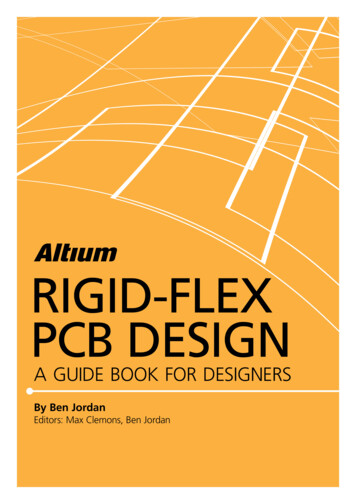
Electrical SpacingTrans LineRF AttenuatorsColor CodeBoard ClassesCalculatorsRegulatorsThis calculator helps with the task of finding the values of the resistors needed for linear and low-dropoutvoltage regulators.For the Standard Type, the output voltage Vout as a function of the reference voltage Vref and resistors R1and R2 is given by:For the 3 terminal type, there is a correction factor due to the quiescent current Iadj flowing from the adjustpin:2
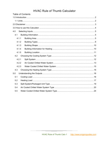
This current is typically below 100 uA and can be neglected with caution.To use this calculator, enter the parameters of the regulator Type, Vref and, if needed, Iadj, select the fieldyou want to calculate (one of the resistors or the output voltage) and enter the other two values.Track-WidthThe Track Width tool calculates the trace width for printed circuit board conductors for a given current andtemperature rise. It uses formulas from IPC-2221 (formerly IPC-D-275).Electrical-SpacingThis table helps finding the minimum clearance between conductors.Each line of the table has a minimum recomended distance between conductors for a given voltage (DC orAC peaks) range. If you need the values for voltages higher than 500V, enter the value in the box in the leftcorner and press Update Values.3
TransLineTransmission line theory is a cornerstone in the teaching of RF and microwave engineering.In the calculator you can choose different sorts of Line Types and their special parameters. The modelsimplemented are frequency-dependent, so they disagree with simpler models at high enough frequencies.This calculator is heavilly based on Transcalc.The transmission line types and the reference of their mathematical models are listed below:Microstrip line:H. A. Atwater, “Simplified Design Equations for Microstrip Line Parameters”, Microwave Journal, pp.109-115, November 1989.Coplanar wave guide.Coplanar wave guide with ground plane.Rectangular waveguide:S. Ramo, J. R. Whinnery and T. van Duzer, "Fields and Waves in Communication Electronics", WileyIndia, 2008, ISBN: 9788126515257.Coaxial line.Coupled microstrip line:H. A. Atwater, “Simplified Design Equations for Microstrip Line Parameters”, Microwave Journal, pp.109-115, November 1989.M. Kirschning and R. H. Jansen, "Accurate Wide-Range Design Equations for the Frequency-DependentCharacteristic of Parallel Coupled Microstrip Lines," in IEEE Transactions on Microwave Theory andTechniques, vol. 32, no. 1, pp. 83-90, Jan. 1984. doi: 10.1109/TMTT.1984.1132616.4
Rolf Jansen, "High-Speed Computation of Single and Coupled Microstrip Parameters IncludingDispersion, High-Order Modes, Loss and Finite Strip Thickness", IEEE Trans. MTT, vol. 26, no. 2, pp. 7582, Feb. 1978.S. March, "Microstrip Packaging: Watch the Last Step", Microwaves, vol. 20, no. 13, pp. 83.94, Dec. 1981.Stripline.Twisted pair.RF-AttenuatorsWith the RF Attenuator utility you can calculate the values of the resistors needed for different types ofattenuators:PITeeBridged TeeResistive SplitterTo use this tool, first select the type of attenuator you need, then enter the desired attenuation (in dB) andinput/output impedances (in Ohms).5
Color-CodeThis calculator helps translating the color bars from the resistor to its value. To use it, first select thetolerance of the resistor: 10%, 5% or equal or smaller than 2%. For example:Yellow Violet Red Gold: 4 7 x100 5% 4700 Ohm, 5% tolerance1kOhm, 1% tolerance: Brown Black Black Brown Brown6
Board-ClassesPerformance ClassesIn IPC-6011 have been three performance classes establishedClass 1 General Electronic Products Includes consumer products, some computer and computerperipherals suitable for applications where cosmetic imperfections are not important and the majorrequirement is function of the completed printed board.Class 2 Dedicated Service Electronic Products Includes communications equipment, sophisticatedbusiness machines, instruments where high performance and extended life is required and for whichuninterrupted service is desired but not critical. Certain cosmetic imperfections are allowed.Class 3 High Reliability Electronic Products Includes the equipment and products where continuedperformance or performance on demand is critical. Equipment downtime cannot be tolerated and mustfunction when required suchas in life support items or flight control systems. Printed boards in this classare suitable for applications where high levels of assurance are required and service is essential.PCB TypesIn IPC-6012B there are also 6 Types of PCB defined:Printed Boards without plated through holes (1)1 Single-Sided BoardAnd Boards with plated through holes (2-6)2 Double-Sided Board3 Multilayer board without blind or buried vias4 Multilayer board with blind and/or buried vias5 Multilayer metal core board without blind orburied vias6 Multilayer metal core board with blind and/orburied vias7
8
To use this calculator, enter the parameters of the regulator Type, Vref and, if needed, Iadj, select the field you want to calculate (one of the resistors or the output voltage) and enter the other two values. 2.2 Track-Width The Track Width tool calculates the trace width for printed circuit board conductors for a given current and temper-