Transcription
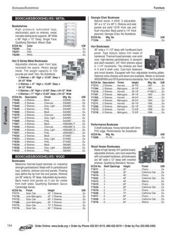
SLLA324 February 2012Application ReportTPD12S016 PCB Layout Guidelines for HDMI ESDRoger LiangHigh Volume LinearABSTRACTTPD12S016 is a multifunction ESD protection device that integrates a HDMIcompliant 55mA load switch, three level shifting buffers, and hot plug detect functionalong with ESD protection for all pins connected to the HDMI connector, includingfour pairs of high speed differential lines. This device targets the mobile sector withthe µQFN package and the set-top-box sector with the TSSOP package. This appnote discusses optimized PCB design guidelines for both packages. With goodlayout design practice, TPD12S016 can fully support HDMI1.4 data rate at 3.4Gbpsand minimize PCB real estate. In addition to using differential lines, othercompensation structures for parasitic capacitance are presented as well.In order to understand layout optimization, HDMI signals are explained in detail.TPD12S016’s TSSOP and µQFN packages both take advantage of the singlestraight line TMDS pin-outs, which allow for simple 45 angle routings.1IntroductionTPS12S016 offers eight ultra low-capacitance ESD clamps, which allow HDMI 1.4 data rates to passthrough while simultaneously providing IEC61000-4-2 (Level 4) ESD protection for all pins connected tothe HDMI connector. The integrated ESD circuits provide good matching between each differential signalpair (data and clock); this is an advantage over discrete ESD solutions where variations between ESDprotection clamps degrade the differential signal quality. TPD12S016 provides a current limited 5V output(5V OUT) at 55mA for sourcing the HDMI power line. 5V OUT and the hot plug detect (HPD) circuitry arecontrolled by the CT HPD pin, which is independent of the level shifting buffer’s control signal LS OE. Aninternal 3.3V node powers the CEC pin, eliminating the need for a 3.3V on board supply. TPD12S016integrates all the external termination resistors on the HPD, CEC, SCL, and SDA lines. The HPD B porthas a glitch filter to avoid false detection due to plug bouncing during HDMI connector insertion. Figure 1shows a simplified circuit schematic and Figure 2 shows an application schematic using two GPIO forHDMI interface control.Key features and benefits of the TPD12S016 include: Supports HDMI1.4 Data Rate Built-in HDMI compliant current limiting load switch Built-in pull-up and pull-down resistors compliant with HDMI1.4 spec Built-in hot-plug-detect Match Class D and Class C pin mapping Auto direction sensing level shifting buffer with integrated pull-ups and a one-shotcircuit (drives at least 750pF load).1
SLLA324 February 2012Figure 1.Figure 2.Circuit SchematicApplication Schematic for HDMI controllers using two GPIO for interfacing2HDMI Signal Types2.1TMDSThere are four sets of high-speed Transition Minimalized Differential Signal (TMDS) lines in HDMIapplication, which include data lines D0 , D1 , D2 , and clock lines CLK . According to HDMI 1.4specification, CLK can reach a maximum speed of 340MHz, with maximum data throughput reaching3.4Gbps on the data lines. During each clock cycle, a package of 10 bits of information is exchanged onthe TMDS lines. The relatively high frequency of these signals makes routing of the lines critical. There aseveral things to keep in mind:2 The number of stubs should be kept to a minimum. Trace lengths should be kept to a minimum. Special care needs to be made to match length in all these lines.
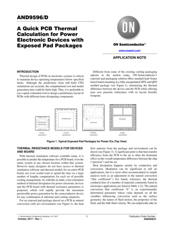
SLLA324 February 2012Application ReportAny significant trace length difference among the differential pairs will introduce signal skew, which couldviolate HDMI specification. Long trace lengths can increase time delay, increase EMI radiation, andcorrupt signal integrity. The high speed lines can be routed differentially or separately. If the lines arerouted through a noisy environment or if they have to be routed relatively long, it may be beneficial toroute them differentially and make the pair 100Ω with respect to each other (not with the ground planeunderneath). Otherwise, 50Ω trace impedance can be used and made with respect to the ground planeunderneath.2.2DDC, HPD, CT HPD/LS OE, VCC5V/5V OUTThe display data channel lines (DDC) are made up of SDA, SCL, and CEC. These lines have internalpull-up resistors and run at 400 kHz or less. The hot plug detect (HPD) signal is a single direction signalthat indicates to a transmitter the presence of a receiver connected on the line. The CT HPD and LS OEcontrol lines enable the HPD scheme and level shifters respectively. They are referenced to VCCA andhave internal pull-down resistors. VCC5V and 5V OUT are the input and output of the load switchrespectively.High speed trace consideration is not needed in routing any of these lines. Traces to and from these pinsshould be routed after those from the TDMS lines are routed first.3RKT package considerationsThe RKT package is suitable for mobile applications where board space is a premium. The packagelength (4mm) closely matches that of the HDMI Type D receptacle footprint; placing TPD12S016RKTclose to the HDMI connector not only makes routing easy but also increases system level ESD protectionrobustness. In an ESD event, the bulk of the energy would be dissipated through the ESD diodes insideTPD12S016RKT before excess energy has time to damage to other ICs on the board. Figure 3 shows thepin outs of the RKT package. Three routing layers are needed: one layer for the Transition MinimalizedDifferential Signal (TMDS) lines, Dx and CLK , and a pair of layers for other signal and power traces.Figure 3.TPD12S016RKT Package pin out3
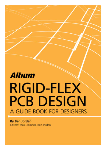
SLLA324 February 2012An example RKT routing to a Type D receptacle pin out is discussed below. Figure 4 shows both theTPD12S016RKT and the Type D footprint on the top layer and the TMDS lines running through vias androuted on the bottom layer. Notice that since Type D receptacles have two rows of pins and that D1 andCLK has to be routed through the bottom layer in order to minimize trace length, it is good practice toroute all differential pairs the same way in order to minimize signal skew between the pairs. When routingthe differential traces to the HDMI controller, keep good differential trace practices as outlined in theappendix.Figure 4.Layout of TMDS Lines Routed on the Bottom LayerFigure 5 shows routing of the non-TMDS lines. Since these do not carry high speed signals, they can berouted with flexibility. Figure 6 shows a hybrid view, combining all three routing layers.Figure 5.4Layout of non-TMDS Lines
SLLA324 February 2012Application ReportFigure 6.Layout of Hybrid Lines5
SLLA324 February 20124PW package considerationsFigure 7.TPD12S016PW Package Pin OutFigure 8 shows a layout example for the TPD12S016PW with HDMI Type A receptacle. Type Creceptacle routing is done in a similar fashion; the TMDS lines would have to be brought in closertogether because of the smaller pitch of the Type C receptacle. Since the PW package is larger and hasno top or bottom pins on the footprint, TMDS traces can be routed straight through on the top layer andonly two layers are needed for routing TMDS plus all other pins. When routing TMDS lines from the HDMItransmitter, through the TPD12S016PW, and to the HDMI connector, one needs to keep differential pairstight and width gap consistent. Minimize trace lengths and do not create angles sharper than 45 . Refer tothe appendix for differential routing guidelines.Figure 8.6TPD12S016PW routing with Type A Receptacle
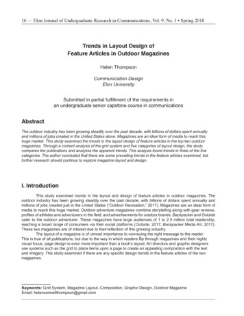
SLLA324 February 2012Application Report5TPD12S016PW EVM BoardAn EVM (evaluation module) was created for testing the TPD12S016PW package. This four layer boardis shown below in Figure 9.Figure 9.TPD12S016EVMThis EVM has three segments. The top segment of the layout uses HDMI Type A connectors. The middlesegment has 2 HDMI Type C connectors. The connectors on the left side of the EVM are on the bottom ofthe board. The bottom segment is designed for user specified additional RC networks. This bottom boardsegment includes an HDMI Type A connector on one side and high speed traces fanned out for probetesting and loading on the other. Eye pattern testing is done for the top DUT; results are shown in Figure10 and 11.Figure 10. Eye diagram using EVM withoutTPD12S016 for the TMDS Lines at1080p, 340MHz pixel clock, 3.4GbpsFigure 11. Eye diagram using EVM withTPD12S016 for the TMDS Lines at1080p, 340MHz pixel clock, 3.4Gbps7
SLLA324 February 20125.1Skinny TracesFollowing HDMI compliance, differential impedance on the TMDS traces is fixed at 100Ω. Figure 12shows a schematic representation of the elementary components of a lossless transmission line; in thiscase the differential trace is the transmission line. Shown in Equation 1, O is the characteristicimpedance of the line, L is the inductance per unit length, and C is the capacitance per unit length. Ourgoal is to keep O at a constant 100Ω throughout the entirety of the differential traces.Figure 12. Lossless Transmission Line Circuit Representation O LCEquation 1Unfortunately, IC pads add capacitive coupling, which decreases O in that general region. Thisundesirable effect can be fixed by adding inductive components. One solution to increase inductance isimplementing special differential traces with higher O called “skinny traces”, which not only provide theinductive effect but also decrease capacitive coupling between the differential trace. Skinny traces helpincreasing the effective O near the IC back to 100Ω. As a rule, skinny traces O should be designed tobe 150Ω in simulation and their length should be one to two times that of the IC pads. Given the exactparasitic IC pad capacitance value, TDR simulation tools such as Hyperlynx should give optimum skinnytrace impedance and length. TPD12S016PW EVM is designed using skinny traces and Figure 13 showsthe dimensions.8
SLLA324 February 2012Application ReportFigure 13. Skinny traces for TMDS linesDuring simulation, parasitic capacitance of the IC pad is combined with 150Ω of skinny trace to produceequivalent impedance at 100Ω. As shown in the eye diagram in Figure 14, skinny traces make the edgesfaster and the eye open wider.Figure 14.Simulated Eye-diagrams with and without Skinny Traces9
SLLA324 – February 2012A.1 AppendixDifferential TracesWhen designing differential traces for a certain characteristic impedance, a number of design software tools canbe used to obtain a reasonable estimate of the trace widths, separations, and thickness for any given impedance.Since trace thickness is not an input for most PCB layout tools, it could be entered into an attached ReadMe filewhen submitting the design to the board shop. Another method would be not to submit a thickness dimension;instead, with a given width and spacing derived from simulation, ask manufacturer to “bake” the board to the rightamount of thickness for a given characteristic impedance. The latter method is preferred. Table 1 shows theoriginal dimensions calculated from SaturnPCB design tools and the returned dimensions from board shop. Mostboard shops have impedance matching capabilities of /- 10%.Table 1.Manufacturer’s Differential Traces RecommendationsTypeOrg acingSimulatedZ (Ω)Impedance (Ω)Tolerance (Ω)100 /-10Differential9.0148.254.76100.136150 /-15Differential5.157.853.6259.38149.759Via and Corners and other ConsiderationsThere are four sets of high-speed TMDS lines per each IC. Since data on these lines reach a max of 3.4Gbps,routing is critical. The number of vias should be minimized on TMDS lines. If a via has to be used, its pad sizeshould be the same as that of the trace width. For example, a via on the 9.1 mils differential trace inTPD12S016PWREVM has a pad size of 9 mils and a drill size of 4 mils. As a rule-of-thumb, anti-pads of radii 15mils (separation between via pad and surrounding copper in the ground and power layer) are used to decreaseparasitic capacitance, which is inversely proportional to the radius of the anti-pad. Using oversized anti-padstakes away the ground layer’s shielding ability. This trade off can be best estimated in simulation tools likeHyperlynx. In Figure 15, the ground layer is shown in blue and TMDS traces are shown in red.Figure 15.High speed TMDS lines routing to HDMI Connector10
SLLA324 – February 2012Figure 16. EVM Top Segment SchematicTPD12S016 PCB Layout Guidelines for HDMI ESD11
IMPORTANT NOTICETexas Instruments Incorporated and its subsidiaries (TI) reserve the right to make corrections, modifications, enhancements, improvements,and other changes to its products and services at any time and to discontinue any product or service without notice. Customers shouldobtain the latest relevant information before placing orders and should verify that such information is current and complete. All products aresold subject to TI’s terms and conditions of sale supplied at the time of order acknowledgment.TI warrants performance of its hardware products to the specifications applicable at the time of sale in accordance with TI’s standardwarranty. Testing and other quality control techniques are used to the extent TI deems necessary to support this warranty. Except wheremandated by government requirements, testing of all parameters of each product is not necessarily performed.TI assumes no liability for applications assistance or customer product design. Customers are responsible for their products andapplications using TI components. To minimize the risks associated with customer products and applications, customers should provideadequate design and operating safeguards.TI does not warrant or represent that any license, either express or implied, is granted under any TI patent right, copyright, mask work right,or other TI intellectual property right relating to any combination, machine, or process in which TI products or services are used. Informationpublished by TI regarding third-party products or services does not constitu
layout design practice, TPD12S016 can fully support HDMI1.4 data rate at 3.4Gbps and minimize PCB real estate. In addition to using differential lines, other compensation structures for parasitic capacitance are presented as well. In order to understand layout optimization, HDMI signals are explained in detail. TPD12S016’s TSSOP and µQFN packages both take advantage of the single